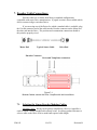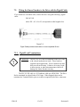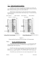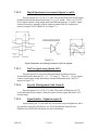
1
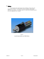
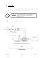
USERS’ MANUAL
FOR
Linear Encoder Options LCA, LCB, LCC,
LCD and LCE
AVAILABLE WITH
MOOG ADVANCED-HIGH FORCE LINEAR MOTORS
UM-103 Revision B
Date: 03/17/09
Linear Encoder Option designed by Motor Option Numbers
LCA, LCB, LCC, LCD and LCE
Moog Components Group
Springfield Operations
750 West Sproul Road
Springfield, PA 19064
Ph: 610-328-4000, Toll Free: 800-510-6885
Fx: 610-605-6216
2009
E-mail: [email protected] Web-site: www.moog.com/components
PAGE INTENTIONALLY LEFT BLANK
Page 1 of 21
Table of Contents:
1.
SAFETY: .................................................................................................................. 4
2.
WARNINGS, CAUTIONS AND NOTES: ............................................................ 4
3.
SCOPE: .................................................................................................................... 7
4.
INTRODUCTION:.................................................................................................. 8
4.1.
Installation Sequence: ................................................................................. 9
5.
INFORMATION FOR DRIVE OR CONTROLLER SETUP: ........................ 10
6.
MECHANICAL MOUNTING NOTES: ............................................................. 11
6.1.
6.2.
6.3.
6.4.
7.
Encoder Alignment: .................................................................................. 11
Dual-Face Mounting: ................................................................................ 12
End-Stops: ................................................................................................. 12
Notes: ........................................................................................................ 12
ENCODER CABLE CONNECTIONS: .............................................................. 14
7.1.
7.2.
7.2.1.
7.2.2.
7.2.2.1.
7.2.2.2.
7.2.2.3.
7.2.2.4.
7.2.2.5.
7.2.2.6.
7.2.2.7.
7.2.2.8.
7.2.2.9.
Selecting the Linear Encoder Modular Cables: ........................................ 14
Wiring the Linear Encoder to the Drive with the Pigtail Cable:............... 15
Pigtail Lead Terminations: ........................................................................ 15
Pigtail cable signal descriptions:............................................................... 16
Encoder and Hall Sensor Power: ...................................................... 16
Digital Quadrature Incremental Signals A and B: ............................ 17
Sin/Cos signals using Option LCE: .................................................. 17
Encoder Misalignment Fault Alarm E: ............................................. 17
Signal Quality / Alignment signal X:................................................ 17
Reference Mark (Z, Vo) and Limit Switch (Vq) signals: ................. 18
Commutation (Hall Sensor) Connections: ........................................ 19
Inner and Outer Shields: ................................................................... 20
Voltage Sense wires Vref+ and Vref-: .............................................. 20
APPENDIX-A: (REVISION HISTORY) ..................................................................... 21
UM-102
3 of 21
Revision B
1. Safety:
Moog motors are capable of producing high forces and velocities. Always
follow appropriate safety precautions when installing and applying these motors.
Equipment should be designed and utilized to prevent personnel from coming in
contact with moving parts that could potentially cause injury.
Read the Moog Linear Motor User’s Manual which applies to the motor you are using
before attempting to operate this device.
Read all cautions, warnings and notes before attempting to operate this device.
Follow all applicable codes and standards.
2. Warnings, Cautions and Notes:
The following conventions are used on the equipment and found in this
manual. Please read all equipment labels and manuals before attempting to use Moog
Linear Motors.
!
WARNING: Identifies information about
practices or circumstances that can lead to
personal injury, property damage, or loss of life
if not correctly followed.
A WARNING identifies information that is critical for identifying and avoiding a hazard
that could lead to serious personnel injury or equipment damage.
!
CAUTION: Identifies information about
practices or circumstances that can lead to
severe equipment damage.
A CAUTION identifies information that is critical to prevent permanent equipment
damage.
UM-102
4 of 21
Revision B
NOTE: Identifies information that is critical for successful
application and understanding of the product.
A NOTE identifies information that is critical for successful application and
understanding of the product.
Follow all warnings and cautions listed in this manual and in the applicable Moog Linear
Motor User’s Manual when working with Moog Components Group High Force Linear
Motors.
!
WARNING: Do not remove the Linear Position Sensor Cover
plates or otherwise disassemble the Linear Position
Sensor. Hands, fingers or clothing may be pinched or
caught in the moving parts.
.
!
WARNING: Do not step onto or apply lateral Loads to the Linear
Position Sensor Housing.
!
CAUTION: The Moog Linear Motor Bearing System is not designed
to support large lateral loads. Lateral loading of the
shaft during movement will limit bearing life and cause
Linear Position Sensor misalignment leading to loss of
position control and phasing.
!
CAUTION: The Moog Linear Position Sensor is not designed to
accommodate shaft rotation. An external torque applied
to the shaft will cause Linear Position Sensor
misalignment leading to loss of position control and
phasing.
UM-102
5 of 21
Revision B
!
!
!
!
!
UM-102
CAUTION: The Moog Linear Position Sensor contains electronic
circuitry that can be damaged by misapplication of
electrical power, or by applying electrical power of the
wrong voltage or polarity. To avoid damaging the
Linear Position Sensor, always use the correct Moog –
approved cable intended for the Drive in use. Ensure
correct sensor power supply voltage and that all
custom sensor cables are properly wired before
applying power.
CAUTION: The Linear Encoder Option is not designed to be
removed, aligned, adjusted, disassembled or installed
by the user.
CAUTION: When pigtail Linear Position Sensor cables are used
(EC series) do not leave stripped wire ends
unprotected. Shorting of the wire ends will damage the
Encoder.
CAUTION: Electrical Phasing of the Linear Position Sensor
Commutation Track is set by the factory and normally
should not require adjustment. Loosening of the
magnet track screws will allow the magnet track to
misalign, resulting in loss of commutation. Excessive
loosening of the magnet track screws will allow the
magnet track to fall toward and strike the Linear Motor
shaft necessitating repair by Moog.
CAUTION: The Moog Linear Position Sensor is not designed to
accommodate shock loads greater than 100 G. Ensure
that the shaft does not slam into either end stop.
Slamming may result in encoder misalignment and / or
damage to the Encoder.
6 of 21
Revision B
3. Scope:
This manual provides information for the installation of Linear Encoder
Options LCA, LCB, LCC, LCD and LCE which are available with the Moog
4020/5020 Linear Motors. For all other aspects of Linear Motor installation, please
refer to the appropriate user’s manual.
Fig 3-1
Linear Encoder Option on a 50204C Motor.
UM-102
7 of 21
Revision B
4. Introduction:
The Linear Encoder Option is provided as a mechanically integral part of the
Linear Motor. Depending upon the motor drive system and the Linear Encoder
option specified, it provides the required Position Feedback, Commutation data,
Reference Mark, Limit switch and Encoder Fault alarm functions.
!
CAUTION:
The Linear Encoder Option is not designed to be
removed, aligned, adjusted, disassembled or
installed by the user.
Typical Servo System with Moog Motor:
Moog Motor with Linear Scale Option LCX
Fig 4-1
Options LCX provide Integral Motor Position Sensing as part of the
Linear Motor System.
UM-102
8 of 21
Revision B
4.1.
Installation Sequence:
Use the following sequence when installing a Moog linear motor the Linear
Sensor Option. Those steps in bold apply specifically to this Linear Encoder
Installation manual.
1. Read the applicable motor installation manual and observe all warnings,
cautions, and notes in Sections 1 and 2 of that manual.
2. Read additionally and observe this manual’s warnings, cautions, and notes
(Sections 1 and 2 of this manual).
3. Properly mount the motor (Section 5 of the Motor Installation Manual).
4. Ensure that no lateral loads or torques are applied to the motor shaft
which will impair encoder operation (Section 6 of this manual).
5. Configure Encoder position signals and Commutation signals to indicate
positive motion consistent with positive Drive effort and positive shaft
movement (Section 7 of the Motor Installation Manual).
6. Make the Encoder cable connections (Section 7 of this manual)
7. Interconnect the motor to the control system (Section 6 of the Motor
Installation Manual).
8. Ensure good electrical shielding and grounding throughout the system
(Section 6.5 of the Motor Installation Manual).
9. Initialize the motor with the control system, limits and controller / Drive
sensing and commutation parameters for the Encoder option used) (Section
7 of the Motor Installation manual).
10. Attach the load in a manner that does not induce or cause binding when the
motor is stationary or moving (Section 5.3 of the Motor Installation Manual).
11. Tune the system for desired performance and accuracy (Section 7.4 of the
Motor Installation Manual).
UM-102
9 of 21
Revision B
5. Information for Drive or Controller Setup:
The motor part number specifies the Linear Encoder Option:
CLD4020D06-LCX-T-CV
LCX is either LCA, LCB, LCC, LCD or LCE. Linear Encoder options A through E
provide different resolutions, signal types, and compatibility. The Interface Control
Drawing for the Linear Encoder option contains the relevant specifications.
Option
Scale
Resolution
Feedback Type
LCA
5 micron
5080
cts/inch
Quadrature Incremental
LCB
1 micron
25400 cts/inch
Quadrature Incremental
LCC
0.5 micron
50800 cts/inch
Quadrature Incremental
LCD
0.1 micron
254000 cts/inch
Quadrature Incremental
LCE
20 micron
See Note 1
Sin/Cos
Table 5-1. Summary of Linear Encoder Options
Note 1: Resolution of the Sin/Cos encoder depends on the level of interpolation
provided by the encoder interface of your control system.
Note that all options provide 120 degree, Positive Hall format Commutation Signals
per NEMA ICS 16.
UM-102
10 of 21
Revision B
6. Mechanical Mounting Notes:
6.1.
Encoder Alignment:
The Linear Encoder Option provides Position Feedback, Commutation data,
Indexing and Home switch functions required to control the Motor.
With the encoder option, encoder and Hall device “heads” are mounted
together on one end of the motor shaft. The heads move with the shaft and read
positional and commutation data from separate, stationary tracks mounted to the
encoder rail.
Fig 6-1
Side loads and Torques may impair encoder alignment.
Linear bearings within the encoder rail physically align the heads and shaft
with the stationary tracks. These bearings also prevent shaft rotation. Do not allow
loads to apply torque or lateral loads to the shaft during installation or use. Do not
apply lateral loads to the Encoder Rail housing. Excessive Torque or Lateral Loads
will cause binding or reduce the life of the bearings within the encoder rail and result
in misalignment of the encoder.
Encoder heads are aligned at the factory before shipping and should not be
adjusted by the user.
UM-102
11 of 21
Revision B
6.2.
Dual-Face Mounting:
Dual-Face Mounting can only be utilized without an integral Moog position
sensor. For information on Dual-Face Mounting please refer to the appropriate
Moog user’s manual.
6.3.
End-Stops:
Two End Stops are provided on the Moog Motor. The internal End Stop is not to be
removed by the user.
Fig 6-2
LCX Option provides an internal End Stop.
6.4.
!
!
UM-102
Notes:
WARNING: Standard End-Stops shipped with Moog motors are not
designed for large loads. Thicker End Stops with
threaded mounting holes are available if needed.
WARNING: Do not remove the Linear Position Sensor Cover
plates or otherwise disassemble the Linear Position
Sensor. Do not operate the Moog Linear Motor with
Linear Position Sensor option when the Linear Position
Sensor cover plates are removed. Hands, fingers or
clothing may be pinched or caught in the moving parts.
12 of 21
Revision B
!
WARNING: Do not step onto or apply lateral Loads onto the Linear
Position Sensor Housing.
!
CAUTION: The Moog Linear Position Sensor is not designed to
accommodate shaft rotation. An external torque applied
to the shaft will cause Linear Position Sensor
misalignment leading to loss of position control and
phasing.
!
CAUTION: The Moog Linear Position Sensor is not designed to
accommodate shock loads greater than 100 G. Ensure
that the shaft does not slam into either end stop.
Repeated slamming will result in encoder misalignment
or malfunction.
!
UM-102
CAUTION:
The FSC-LC-XX cable is terminated on the Drive End
with colored insulated wire leads. These leads are
supplied with unstripped ends. Don’t strip any ends
that you will not be using. This may result in short
circuits, or other misconnections which will damage
the Linear Encoder circuitry.
13 of 21
Revision B
7. Encoder Cable Connections:
Encoder cables are available from Moog in standard configurations
compatible with major Drive manufacturers. A pigtail version is also available which
allows custom wiring to suit other Drives.
If you are using one of the Drives for which a standard cable is available, plug
the Circular connector end of the cable into the Encoder connector on the Motor and
the other end into the Drive. The position and commutation connections should at
this point be properly wired.
Motor End
Typical Sensor Cable
Drive End
Encoder Connector
Drive and Temp Sense connectors
Figure 7-1
Modular Cables connect the Drive / Amplifier with the Linear Motor.
7.1.
Selecting the Linear Encoder Modular Cables:
Modular Cables. Wiring can be greatly simplified if a Drive or Amplifier is
used for which a Moog standard cable already exists. See Moog product literature to
select a cable on the basis of Drive model and required cable length.
UM-102
14 of 21
Revision B
7.2.
Wiring the Linear Encoder to the Drive with the Pigtail Cable:
If you cannot use a modular cable, connect the drive using the following “pigtail”
cable:
FSC-EC-XX
where XX = 02, 10 or 25, corresponds to cable length in feet.
Figure 7-2
Pigtail Cable provides termination to most compatible Drives.
7.2.1. Pigtail Lead Terminations:
CAUTION:
!
The FSC-EC-XX cable is terminated on the Drive End
with colored insulated wire leads. These leads are
supplied with stripped ends. Trim or insulate any ends
that you will not be using. Failure to do so may result
in short circuits, or other misconnections which will
damage the Linear Encoder circuitry.
The FSC-LC-XX cable is a 30 Conductor cable per AWM 2464. The Drive
End is terminated in colored leads of 24 Gauge. When stripped, these can be
terminated to Terminal Blocks, pins or sockets as required by the Drive connectors.
UM-102
15 of 21
Revision B
7.2.2.
Pigtail cable signal descriptions:
In addition to sensor power, five general types of signals are accessed by the
Linear Encoder connector: Position, Hall, Fault / Signal Quality, Reference Mark and
Index. Additional, auxiliary pins are reserved for future use.
Identify and wire the Encoder Power and signals for Position, Commutation,
Encoder Fault, Reference Mark and Index functions per Figure 7-4 and the following
signal descriptions.
Drive Connector
Motor Connector
Drive Connector
Motor Connector
Figure 7-3
Pinouts and Wire Colors for the FSC-EC-XX Cable / LCX Encoder option.
7.2.2.1.
Encoder and Hall Sensor Power:
The Position Sensor requires DC Power at 5.0 V +/- 5% at the Encoder Cable
leads providing at least 100 mA DC. The Encoder power supply is applied to +5V
and GND at pins 1 and 2 respectively.
The Hall sensor head is powered separately from the Encoder and requires DC
Power at 5.0 V +/- 5% at the Encoder Cable leads, providing at least 20 mA DC. The
Hall sensor power supply is applied to +5V and GND at pins 17 and 18 respectively.
If both Hall sensor and Encoder are used, connect both grounds and +5V pins.
UM-102
16 of 21
Revision B
7.2.2.2.
Digital Quadrature Incremental Signals A and B:
Encoder options LCA, LCB, LCC and LCD provide Differential Mode Digital
Quadrature Incremental Encoder data lines A+, A-, B+ and B-. These 0 to 5V (TTL
level) signals connect to both single ended and Differential mode “A quad B” inputs
and are electrically compatible with the industry standard RS-422 transmission
protocol using the 26LS31 Buffer IC per Figure 7-4.
Figure 7-4
Digital Quadrature and Analog Quadrature (Sin/Cos) signals.
7.2.2.3.
Sin/Cos signals using Option LCE:
Encoder option LCE provides Differential Mode Quadrature Sin/Cos
Incremental Encoder data lines V1+, V1-, V2+ and V2-. These 0.3 – 1.2Vpp signals
connect to both single ended and industry standard Differential mode “Sin/Cos”
inputs per Figure 7-4.
7.2.2.4.
Encoder Misalignment Fault Alarm E:
Encoder options LCA, LCB, LCC and LCD provide a HIGH state on TTL
level Differential alarm outputs E when the optical encoder signal falls below 45%
nominal range.
7.2.2.5.
Signal Quality / Alignment signal X:
Signal Quality pin X is provided only for encoder setup and alignment, and is
not generally required by the Motor User. See the Installation manual for the
Renishaw series RGH Encoder Heads for more information.
UM-102
17 of 21
Revision B
7.2.2.6.
Reference Mark (Z, Vo) and Limit Switch (Vq) signals:
A Differential Mode TTL Level (0-5V) voltage signal, active “HIGH”
provides an accurate absolute position reference to designate the rated Mid stroke
shaft position. (The Reference Mark is designated “Z” in options LCA, LCB, LCC
and LCD and “Vo” in option LCE).
Figure 7-5
Electrical ports for Reference Mark and Limit Switch signals
A Limit Switch signal Vq is pulled low by a single ended Open Collector TTL
Level (0 to 5V) signal when the shaft is within 0.25 inches (10 mm) of either End – of
– Rated Stroke shaft position as shown in Figure 7-6.
Figure 7-6
Reference Mark Limit Switch Location.
UM-102
18 of 21
Revision B
The Reference Mark is Synchronous with both Digital and Analog Quadrature
signal phase.
Repeatability of the Reference mark is limited in Digital and Analog sensors
by one quadrature Line Count or by +0 / -18 degrees of Sin/Cos signal phase
respectively.
Figure 7-7
Reference Mark Signal is synchronous with Quadrature Encoder Signals.
The Limit Switch signal Vq is asynchronous with respect to the Quadrature
Encoder signal phase. Repeatability of the Limit Switch positions is +0 / -0.1 mm
(.004 inches).
7.2.2.7.
Commutation (Hall Sensor) Connections:
0 to 5V (TTL level) Differential mode Hall sensor signals are electrically
compatible with the industry standard RS-422 transmission protocol using the
26LS31 Buffer IC. These signals are compatible with Drive Hall sensor inputs
equipped with or without pull up resistors.
Figure 7-8
Hall Sensor Outputs.
UM-102
19 of 21
Revision B
7.2.2.8.
Inner and Outer Shields:
Inner and Outer shields mitigate the effects of electrical noise on the encoder
signal. In typical installations the inner shield is connected to encoder and / or Hall
input signal Ground, and the outer shield to the Drive / Controller chassis.
Figure 7-9
Inner and Outer Shield connections.
Grounding and Shielding of the Drive cables are also important for safety and
for proper sensor electrical noise immunity. For more detail in system Grounding and
Shielding, please see the Moog Linear Motor User’s Manual.
CAUTION:
!
7.2.2.9.
Poor ground or shield connections or wiring can cause
unpredictable motion, and could damage the motor,
control system or machine.
Voltage Sense wires Vref+ and Vref-:
In Option LCE, Vref+ and Vref- provide remote voltage sensing for regulation
of the Encoder Power Supply to compensate for Encoder Power Supply voltage drop
in long encoder cables. If remote sensing is not provided in the Drive, Vref+ and
Vref- can be used as additional (paralleled) encoder power conductors by connecting
Vref- and Vref+ to Ground and +5V respectively..
UM-102
20 of 21
Revision B
Appendix-A: (Revision History)
ECO # Revision
0112
A
B
UM-102
Change
Initial Release
Moog Update
Date
_
April 1, 2003
March 17, 2009
21 of 21
Revision B