1
Application Note: 254
Adding Support for New Devices in MDK Version 5
Abstract
This application note is intended to assist chip vendors to provide support for new devices in MDK-ARM Version 5 as
quickly as possible. The numerous questions that arise concerning the support in third-party development tools are
answered by a checklist describing all tasks that are necessary to fully integrate a new device into the toolchain. Finally, all
generated files have to be put together in a Device Family Pack (DFP).
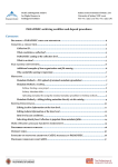
Contents
Abstract ..................................................................................................................................................................................................................... 1
Integration Tasks ..................................................................................................................................................................................................... 1
Data Sheets and User Manuals ........................................................................................................................................................................ 1
System View Description (SVD) ..................................................................................................................................................................... 2
Device Header, Startup, and System Files .................................................................................................................................................... 2
Debug Support .................................................................................................................................................................................................... 2
Flash Programming Algorithm ......................................................................................................................................................................... 2
Device Family Pack (DFP) ................................................................................................................................................................................. 2
How to Write a Device Family Pack .................................................................................................................................................................. 3
Step 1: Specifying the Devices ......................................................................................................................................................................... 3
Step 2: Creating Conditions and Adding Software Components........................................................................................................... 4
A Consistent Driver Interface ......................................................................................................................................................................... 5
Step 3: Adding Examples and Code Templates ........................................................................................................................................... 6
Helpful Files and Tools ........................................................................................................................................................................................... 6
Revision History ...................................................................................................................................................................................................... 6
Integration Tasks
CMSIS, a common standard for ARM devices, makes it easy to add support for a new device based on ARM CortexM0/M0+, Cortex-M3, or Cortex-M4 cores. For devices that do not require compiler and assembler changes (because of no
new instructions, computational accelerators, or multiple data pointers), integration into MDK-ARM Version 5 is fairly
simple. The following list describes all required integration tasks:
Data Sheets and User Manuals
System View Description (SVD)
Device Header, Startup, and System Files
Debug Support
Flash Programming Algorithm
Device Family Pack (DFP)
Data Sheets and User Manuals
Data sheets, product specifications, reference and user manuals are created by the chip vendor. Using the Device Family
Pack (DFP), device documentation is integrated into the Books tab in µVision where it can be accessed by the end-user.
Add Support for New Devices in MDK Version 5
System View Description (SVD)
The System View Description (SVD) is XML-based and vendor independent. It outlines the programmer's view, in
particular the memory mapped registers of the peripherals. The level of detail contained in the system view descriptions is
comparable to what is found in device user manuals. The information ranges from a high-level functional description of a
peripheral all the way down to the definition and purpose of an individual bit field in a memory mapped register.
The CMSIS-SVD files can be used to generate device header files. Debuggers use the information in the SVD file for
providing device-specific views of peripherals.
Device Header, Startup, and System Files
A device header file defines the peripheral registers and interrupt numbers (IRQn) of a device. This file is included in C
and assembler programs so that the end-user does not need to define the SFRs or peripheral registers. Device header files
can be automatically generated from SVD files.
For Cortex-M processor based devices, the startup file configures the tool-chain specific compiler run-time environment
whereas the system file configures device features (clock, bus system, XTAL frequency, PLL settings).
The CMSIS standard defines the structure of these files for Cortex-M processor based devices. Instructions and template
files for adaption to new device(s) are available here: www.keil.com/pack/doc/cmsis/Core/html/_templates_pg.html.
Debug Support
The µVision debugger can be used to debug programs running on target hardware. This is accomplished with a DLL that
connects to the hardware. MDK provides support for several types of hardware, including the new CMSIS-DAP standard.
For Cortex-M processor based devices, the ULINK family of debug adapters uses a device internal ROM table to adapt to
ARM CoreSight debug and trace features. Supporting new Cortex-M devices is therefore done automatically and does not
require any change to existing drivers.
Flash Programming Algorithm
For the ULINK family of debug adapters the Flash Programming Algorithm is provided as *.FLM file (for Cortex-M).
These algorithms can also be used with CMSIS-DAP or other JTAG adapters such as the SEGGER J-LINK series. Refer to
www.keil.com/pack/doc/CMSIS/Pack/html/_flash_algorithm.html for more information on how to create a new FLM file.
Device Family Pack (DFP)
A Device Family Pack (DFP) is a Software Pack that contains
Information about the processor and its features.
Parameters, technical information, and data sheets about the device family and the specific devices.
Device description and available peripherals.
Memory layout of internal and external RAM and ROM address ranges.
Flash programming algorithms for the device.
Debug and trace configurations as well as System View Description (SVD) files for device specific display of the
memory mapped peripheral registers.
C and assembly files for the device startup and access to the memory mapped peripheral registers.
A Software Pack is a ZIP archive (with the filename extension “PACK”) containing all required libraries and files and a
package description file (PDSC) with all the information about the Software Pack in XML format. The structure of a
Software Pack is defined in CMSIS. Refer to CMSIS-Pack (www.keil.com/CMSIS/Pack) for more information. The following
describes how to create a DFP from scratch. You can use the template file that is part of the application note’s ZIP file
(apnt_254.zip) for creating your own DFP. It is available at www.keil.com/appnotes/docs/apnt_254.asp.
Many pre-built DFPs are available that can be used as a starting point for creating your own Software Pack. After installation
using the Pack Installer, you will find them for example in C:\Keil\ARM\Pack\Keil.
It is assumed that the reader is familiar with AN251 “Creating Software Packs for Software Components”:
www.keil.com/appnotes/docs/apnt_251.asp. AN256 describes how to publish a Software Pack to a wider audience:
www.keil.com/appnotes/docs/apnt_256.asp.
Copyright © 2014 ARM Ltd. All rights reserved
Application Note: 254
2
www.keil.com
Add Support for New Devices in MDK Version 5
How to Write a Device Family Pack
Step 1: Specifying the Devices
A DFP starts in the same manner as any other Software Pack. You need to specify the XML schema, a <vendor>, a
<name> for the DFP and a <description>. Sections containing release information and keywords follow this header.
For more information on the PDSC format, refer to AN251.
The <devices> section is specific for DFPs. In this section you need to describe a device <family> or <subFamily>.
A single <device> is part of a family or subFamily. The following properties describe a family/subFamily/device:
The <description> element contains a brief summary of the family/subfamily/device.
<feature> elements describe the device peripherals.
<book> elements are used for documentation such as data sheets or user manuals.
<processor> elements specify the features of the device’s processor.
<compile> elements declare device specific settings for the build tools.
<debug> elements show device specific information for debuggers (including System View Description files).
<memory> elements specify the memory layout of a device (for internal and external RAM and ROM)
<algorithm> elements define the device specific Flash programming algorithms.
For more information on these properties, refer to CMSIS-Pack - /package/devices level.
A device will inherit the specifications from both the family and subFamily. Some properties are required to be unique.
Therefore, properties specified on the family level can be redefined by the property on the subFamily or device level.
Information like the description and feature entries are concatenated, starting with the information from the family and subfamily level and finalizing with the information on the device level.
<devices>
<!-- **************************** KEIL32M Series **************************** -->
<family
Dfamily="KEIL32M Series" Dvendor="ARM:82">
<processor Dcore="Cortex-M4" DcoreVersion="r0p1"
Dfpu="1" Dmpu="1" Dendian="Little-endian"/>
<compile
header="Device\Include\Keil32Mxx.h"/>
<algorithm name="Flash\KEIL32Mxx.flm" default="0"/>
<book
name="Documents\MCBKeil32M.chm" title="MCBKEIL32M User's Guide"/>
<description>
KEIL32M devices are demo applications and provide many peripherals.
- At 166 MHz CPU clock: over 200 DMIPS executing from Flash memory
- SMART Accelerator for Flash access
- Versatile Memory Controller supports Compact Flash, SRAM, NOR and NAND
</description>
<feature type="TimerOther" n="1" name="Independent Watchdog Timer"/>
<feature type="TimerOther" n="1" name="Window Watchdog Timer"/>
<feature type="Other"
n="1" name="Temperature Sensor"/>
<feature type="CoreOther" n="1" name="CRC Calculation Unit"/>
<feature type="DMA"
n="16" name="General Purpose DMA "/>
<feature type="PowerOther" n="1" name="POR, PDR, and BOR"/>
<feature type="XTAL"
n="4000000" m="26000000" name="Crystal Oscillator"/>
<feature type="IntRC"
n="16000000" name="Internal Factory-Trimmed RC"/>
<feature type="IntRC"
n="32000"
name="Internal 32 kHz RC with Calibration"/>
<feature type="RTC"
n="32000"
name="Battery backed 32 kHz RTC"/>
<feature type="Temp"
n="-40"
m="85"/>
<!-- ****************************** KEIL32M01 ****************************** -->
<subFamily
DsubFamily="KEIL32M01">
<processor Dclock="84000000"/>
<compile
header="Device\Include\Keil32Mxx.h" define="KEIL32M0XX"/>
<debug
svd="SVD\KEIL32M0x.svd"/>
<algorithm name="Flash\KEIL32Mxx.FLM" start="0x1FFF7800" size="0x0210" default="1"/>
<book
name="Documents\KEIL32Mxx_UM.PDF" title="KEIL32M Series User Manual"/>
<book
name="Documents\KEIL32M01_DS.PDF" title="KEIL32M01 Data Sheet"/>
<feature type="Timer" n="7"
m="32" name="General Purpose Timer"/>
<feature type="Timer" n="1"
m="16" name="Enhanced Control Timer"/>
<feature type="I2C"
n="3"/>
<feature type="USART" n="3"
name="3 x USART Interface up to 4 Mbit/s"/>
Copyright © 2014 ARM Ltd. All rights reserved
Application Note: 254
3
www.keil.com
Add Support for New Devices in MDK Version 5
<feature type="USBOTG" n="1"
name="USB OTG (Full-Speed) with PHY"/>
<feature type="VCC"
n="1.8" m="3.6"/>
<feature type="NVIC"
n="50"/>
<!-- ****************************** KEIL32M01xA **************************** -->
<device
Dname="KEIL32M01FA">
<memory id="IROM1" start="0x08000000" size="0x20000" startup="1" default="1"/>
<memory id="IRAM1" start="0x20000000" size="0x10000" init
="0" default="1"/>
<algorithm name="Flash\KEIL32Mxx_128.FLM" start="0x08000000" size="0x20000"
default="1"/>
<feature type="SPI" n="2" name="2 x SPI, up to 50 Mbit/s"/>
<feature type="ADC" n="10" m="12"/>
<feature type="IOs" n="36"/>
<feature type="QFP" n="48" name="LQFP 48 7x7x0.5"/>
</device>
</subFamily>
</family>
</devices>
Step 2: Creating Conditions and Adding Software Components
A condition describes dependencies on device, processor, and tool attributes as well as on the presence of other
components. Each condition has an id that is unique within the scope of the PDSC file. An id can be referenced in the
condition attribute of software components, APIs, examples, and files.
In general, a DFP uses conditions with regard to the compiler, device family, a peripheral, or CMSIS.
<conditions>
<condition id="Compiler ARM">
<require Tcompiler="ARMCC"/>
</condition>
<condition id="KEIL32M0xxx">
<description>ARM KEIL32M Series devices</description>
<require Dname="KEIL32M0???"/>
</condition>
<condition id="KEIL32M1xxx">
<description>ARM KEIL32M1x Devices</description>
<require Dname="KEIL32M1???"/>
</condition>
<condition id="KEIL32Mxx CMSIS Device">
<description>ARM KEIL32M Series devices and CMSIS-CORE</description>
<require Cclass="CMSIS" Cgroup="CORE"/>
<require Dvendor="ARM:13" Dname="KEIL32M????"/>
</condition>
<condition id="KEIL32Mxx CMSIS GPIO">
<description>ARM KEIL32M Series GPIO Driver with CMSIS</description>
<require Cclass ="CMSIS" Cgroup="CORE"/>
<require Dvendor="ARM:13" Dname="KEIL32M????"/>
<require Cclass ="Device" Cgroup="GPIO" />
</condition>
</conditions>
Note:
The Dname attribute can be used with wild-cards ('*' or '?') to match many devices names.
For more information on the allowed conditions, refer to CMSIS-Pack - /package/conditions level.
Software components add files to a project depending on the conditions that are fulfilled by its properties. The following
example uses the condition “KEIL32Mxx CMSIS Device” to add all kinds of files (startup, Flash algorithm, device
configuration, and peripheral drivers) to a project.
In the context of a DFP, software components carry the required source code and header files for device support and may
add #defines to the RTE_Components.h file. Software components (for example device peripheral drivers) are an
important part of a DFP.
<components>
Copyright © 2014 ARM Ltd. All rights reserved
Application Note: 254
4
www.keil.com
Add Support for New Devices in MDK Version 5
<component Cclass="Device" Cgroup="Startup" Cversion="1.0.0" condition="KEIL32Mxx CMSIS
Device">
<description>System Startup for ARM KEIL32M Series</description>
<RTE_Components_h>
<!-- the following content goes into file 'RTE_Components.h' -->
#define RTE_DEVICE_STARTUP_KEIL32Mxx
/* Device Startup for KEIL32M */
</RTE_Components_h>
<files>
<file category="source" name="Device\Source\ARM\KEIL32Mxx_OTP.s"
attr="template" select="Flash One-Time programmable Template"/>
<file category="header" name="Device\Include\Keil32Mxx.h"/>
<!-- startup files -->
<file category="source" name="Device\Source\ARM\startup_Keil32Mxx.s" attr="config"/>
<!-- system file -->
<file category="source" name="Device\Source\system_Keil32Mxx.c" attr="config"/>
<!-- device configuration required by drivers at the moment -->
<file category="header" name="RTE_Driver\Config\RTE_Device.h" attr="config"/>
</files>
</component>
<component Cclass="Device" Cgroup="GPIO" Cversion="1.0.0" condition="KEIL32Mxx CMSIS
Device">
<description>GPIO driver used by RTE Drivers for KEIL32M Series</description>
<files>
<file category="header" name="RTE_Driver\GPIO_KEIL32Mxx.h"/>
<file category="source" name="RTE_Driver\GPIO_KEIL32Mxx.c"/>
</files>
</component>
</components>
Note: For more information on how to describe software components, refer to CMSIS-Pack - /package/components level.
A Consistent Driver Interface
To enable the various middleware stacks to utilize the peripherals of a microcontroller device, a standardized interface is
necessary. CMSIS-Driver provides this consistent driver interface for accessing common peripherals. For each enabled
peripheral of the microcontroller, a control structure is provided that is the interface to the middleware. The DFP should
provide drivers for most of the communication peripherals integrated on the device.
At the moment, the following device driver interfaces are defined as an API in CMSIS-Driver:
Ethernet: Interface to Ethernet MAC and PHY peripheral.
I2C: Multimaster serial single-ended bus interface driver.
MCI: Memory Card Interface for SD/MMC memory.
NAND: NAND Flash memory interface driver.
NOR: NOR Flash memory interface driver.
SPI: Serial Peripheral Interface bus driver for 8-bit master.
UART: Universal Asynchronous Receiver/Transmitter interface driver.
USB: USB driver interface for generic USB Host and Device communication.
These generic device driver APIs cannot cover every potential use-case of a peripheral type. For example the Ethernet
API is not suitable for the Precision Time Protocol defined in IEEE1588. In a similar way the UART API does not support
SmartCard interfaces. However, the defined API interfaces support a wide range of use cases. It is possible to extend a
device class with further device APIs to cover new use-cases.
A DFP may contain additional peripheral driver interfaces to extend the standard APIs. For example, drivers for Memory
BUS, GPIO, or DMA may be part of the DFP and referenced by the implementation of the standard APIs.
Note:
An introduction into CMSIS-Driver can be found here: www.keil.com/cmsis/driver.
Using CMSIS-Driver is not mandatory but strongly recommended.
Further details about software components can be found in the first chapter of AN251 and in CMSIS-Pack /package/components level.
Copyright © 2014 ARM Ltd. All rights reserved
Application Note: 254
5
www.keil.com
Add Support for New Devices in MDK Version 5
Step 3: Adding Examples and Code Templates
Ready-to-use example projects and user code templates enhance the customer’s experience and help to give him a quick
start for implementing his application. For more information how to add example projects and user code templates to a
Software Pack, please read chapter 5 of AN251.
Helpful Files and Tools
Here’s a list of files and tools that help you to successfully generate a PDSC file and the complete DFP:
Tool
Notepad++
notepad-plus-plus.org/
Purpose
Helps to create a XML-based PDSC/SVD file. Can check the syntax automatically (if XML
file and schema file reside in the same directory).
Visual Studio (Express)
www.visualstudio.com/
Same as Notepad++
PACK.xsd
Schema file for PDSC XML syntax checking. Resides in the MDK installation directory (for
example C:\Keil\UV4).
SVDConv.exe
Checks the semantics and consistency of the data contained in a CMSIS-SVD file. Creates
header files from SVD. Resides in the MDK installation directory (usually C:\Keil\UV4).
CMSIS-SVD_Schema_1_0.xsd
Schema file for SVD XML syntax checking. Resides in the CMSIS-SVD directory (for
example C:\Keil\ARM\Pack\ARM\CMSIS\3.20.4\CMSIS\SVD)
Revision History
January 2014: Initial Version
Copyright © 2014 ARM Ltd. All rights reserved
Application Note: 254
6
www.keil.com