1
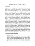
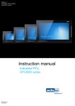
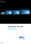
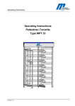
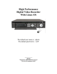
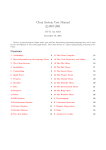
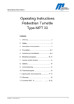
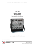
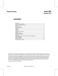
4MP3-MSC User Manual For V2.x Hardware
1. Introduction
The 4MP3-MSC is a versatile general-purpose standalone or computer controlled controller for
multimedia shows, museum exhibits and themed attractions. It operates DVD, LD and CD
players, musical instruments, lighting controls and other serial devices using RS-232, RS-422 or
MIDI interfaces. It has 4 MP3 decoders that can play 4 MP3 files simultaneously from a compact
flash card. Up to 15 hours of CD-quality stereo audio can be stored and played from a single
controller unit. Each controller responds to closures (button pushes) or voltage inputs on its
optically isolated digital input ports, or commands from its eight serial ports. Optically isolated
digital output ports drive tally lights or other low current devices and relays. Two relay closures
are also available. Digital output ports can be configured to generate PWM signals providing
dimming of tally lights or driving servo motors. The rear panel connectors on the digital I/O and
relay ports permit switches, lamps, etc. to connect directly to the controller without punch blocks
or other intermediate wiring devices for power and ground bussing.
Multiple controllers can be controlled directly by a computer via the 10BASE-T port. Standalone
operations are achieved with ShowgramV4, a flexible and powerful scripting language.
ShowgramV4 scripts are downloaded into non-volatile memory in the controller via 10BASE-T.
Once downloaded, the scripts take over scheduling and detection of events. Central scheduling
and error reporting are also available on the host computer. Please consult the ShowgramV4
Language Manual for language and programming details.
The controller can communicate with other host devices with UDP protocol. A Windows PC
front-end program is also available for direct control of the hardware resources and downloading
of ShowgramV4 scripts. A Windows OCX is supplied for building custom user interfaces with
Visual Basic, Visual C++, Delphi or other graphical user interface design programs. The same
UDP protocol allows multiple controllers to communicate with each other to share network
variables and hardware resources.
2. Hardware Features and Configurations
a. Front and Back Panels
Figure 1 shows the layout of the front panel. The unit can be turned on or off with the
POWER switch. The 4-line LCD display and the 5-button keypad provide easy unit
configuration and display of user generated information. The CPU LED acts as a
heartbeat of the controller. It blinks on for 1 second every 2 seconds when the controller
is functioning normally. The DATA LED blinks on whenever there is valid data packet
sent to the host serial port. The LOCK LED is on when the controller is locked on to a
valid audio master clock. The CLIP LED blinks on whenever there is a clipping in one or
more of the audio output channels. The compact flash memory can be installed via the
small access window. Two trim pots are also accessible through the same window for
adjustment of SMPTE input and output levels.
Figure 2 shows the layout of the back panel. Both AC and DC power supplies can be
used. Table 1 shows the connection of external powers to the controller. Power for the
main PC board of the controller should be applied at Pin 3 and 4 of the power connector
(labeled as PWR). Power for the optically isolated inputs and outputs should be applied at
Pin 1 and 2 (labeled as LMP). Power connected to Pins 1 and 2 is rectified and filtered to
produce the isolated supply (VISO), so AC or DC power supplies may be used. When DC
power supplies are used, the controller works with either polarity of the power supplies.
The remaining connectors on the back panel will be described in the following sections.
CPU
1
0
DATA
LOCK
POWER
CLIP
Figure 1. Front Panel Layout
adat
Figure 2. Back Panel Layout
Pin
1
2
3
4
Descriptions
Power for optically isolated inputs,
outputs and all the serial ports
Power for optically isolated inputs, outputs and
serial ports
Power for main PC board
Power for main PC board
Table 1. Back Panel Power Connector
b. Serial Ports
There are 8 device ports. Device ports 1 to 4 are RS-232 only. Port 5 can be RS232 or
MIDI. The DB9 connector labeled Port 6 has two different ports. The RS-232 pins
provide a general purpose RS232 port, Port 6. The RS-422 pins provide a dedicated
DMX port. Port 7 and 8 can be RS-232 or RS-422. The baudrate, parity and the number
of bits for the device ports are settable from the host computer or by ShowgramV4
commands. The available baudrates are listed in Table 2. Baudrate of port 5 must be set
to 31250 when configured as a MIDI port. Table 3 shows the pin-outs of the DB-9
connectors on the back panel.
Port
1 to 8
DMX
Baudrates
300, 600, 1200, 2400, 4800, 9600, 19200, 31250,
38400, 56000, 57600, 115200, 125000, 250000
250000
Table 2. Available baudrates
In addition to plain byte transfer between the controller and external serial devices, the
controller has built-in support for the Pioneer Laser Disk protocol. A video black-burst
signal can be connected to the Video Sync In connector on the back panel to synchronize
video playback from multiple units. Commands are available to synchronize output to the
serial device ports to within a single video frame.
Pin
1
2
3
4
5
6
7
8
9
Port 6 to 8
RS422 RXRS232 RXD
RS232 TXD
RS422 TX+
GND
RS422 RX+
Port 1 to 5
RS232 RXD
RS232 TXD
GND
RX422 TX-
Analog
ADC1 In
ADC3 In
+5V Out
DAC1 Out
DAC GND
ADC2 In
ADC4 In
ADC GND
DAC2 Out
Table 5. DB-9 pin-out descriptions
c. 5V Analog Inputs and Outputs
The pin-outs of the DB-9 connector labeled as ANALOG are listed in Table 5.
There are 4 analog-to-digital input channels and 2 digital-to-analog output
channels. The input and output voltage range is 0 to 5V. The analog-to-digital
converter precision is 12-bit and the digital-to-analog converter is 10-bit. The
converted digital values of the ADCs are mapped directly to 4 integer variable in
ShowgramV4: “adc1”, “adc2”, “adc3” and “adc4”. A typical application for the
ADC is to connect a potentiometer to the +5V, DAC GND and one of the inputs
for global volume control. The DACs are mapped to 2 integer ShowgramV4
variables: “dac1” and “dac2”.
d. Optically Isolated Closure/Logic Inputs
There are 24 optically isolated closure/logic inputs for drive voltage up to 24VDC.
Current limiting resistors are included on-board allowing simple contact closures to be
used. Inputs 1 to 12 may be configured with ShowgramV4 scripts to provide 6 quadrature
counters.
VISO
4MP3-MSC
•
•
opto-Isolated input (I terminal)
GNDISO
Figure 3 Typical connection of a contact closure to a digital input.
There is a 5-button keypad on the front panel. At power up, these buttons default to front
panel menu manipulation mode for controller configurations and manual manipulations
of hardware resources and start/stop of ShowgramV4 cues. The menu system is described
in a later section. When these buttons are left idle for 30 seconds, the front panel LCD
display switches to general purpose user display from the ShowgramV4 script. In this
mode, the front panel bush buttons become general purpose digital inputs that can be
accessed from ShowgramV4 scripts as upKey, downKey, leftKey, rightKey and enterKey
(center button).
There is also a SAFETY button which is hidden inside a small hole on the bottom left
corner of the keypad. Pushing this SAFETY button with the center keypad button held
down would change the front panel back to menu manipulation mode.
e. Optically Isolated Lamp Driver/Logic Outputs
In parallel with the inputs are 24 optically isolated lamp driver/logic outputs capable of
driving up to 24VDC at 250mA of current per output. All Outputs can be configured to
generate PWM signals. The minimum PWM frequency is 61Hz. A typical connection is
shown in Figure 4.
The inputs and outputs are in parallel in the sense that nth input and nth output share the
same physical connection. Therefore if you connect a push button to input 1 and a tally
light to output 1, pushing the button would turn on the tally light. Similarly when output 1
is driven low (turn on the tally) by the ShowgramV4 script, input 1 would be read as low,
i.e. as if the push button is pushed. However, there is a way to allow using the push
button and the tally light simultaneously. From the ShowgramV4 script, you may declare
an .IO option for an output. Once this option is turned on, the 4MP3-MSC hardware
periodically turns off the output driver momentarily to sample the input state. For the
example above, the tally light would be turned off briefly so that the state of the push
button can be read. The turn off period is only about 50us and usually won’t cause any
blinking effects on the tally light. The .IO option must be used with caution and should be
avoided if the output device (device connected to the output) cannot tolerate any glitches
of the output state.
VISO
•
+ terminal
load
4MP3-MSC
•
Control
GNDISO
opto-Isolated output (O terminal)
Figure 4. Typical connection of a load to the opto-isolated output.
f.
Relay Closures
There are 2 relay closures with both Normally-Open and Normally-Close connection
available at the back panel.
g. Audio Playback System
The controller has four MP3 decoders on board, a 10 analog audio inputs, 8 analog audio
outputs and two Alesis ADAT interfaces, providing a total of 26 audio input channels and
24 audio output channels. Input channels 1 to 8 go to 24-bit ADCs and channels 9 and 10
go to a 18-bit ADC. Input 1 to 8 are typically used for volume control of DVD player
outputs and channels 9 and 10 and are intended for adding paging system audio to the
output of the mixer.
Figure 5 shows internal configuration of the onboard Analog Device SHARC DSP mixer.
It supports a cross-point matrix of size up to 18 x 24, allowing mixing, fading and
panning of any of the 18 inputs to any of the 24 output channels. Each channel’s level can
be modified by the 3 multipliers shown in Figure 5. The 3 multipliers are mapped to
predefined floating point variables in ShowgramV4 scripts. Each output channel has a
parametric EQ filter bank and a delay of up to 225ms.
There are two different configurations for the 4MP3-MSC controller, the FULL version
has all the hardware features and the MSC-ONLY version that has no MP3 decoders. For
the MSC-ONLY version, inputs 1 to 8 of the DSP mixer matrix are mapped to the 8
analog audio inputs. However, for the FULL version, inputs 1 to 8 of the mixer matrix
can be either the MP3 decoder outputs or the analog audio inputs. The selections are
under ShowgramV4 script control. The selections are made pair-wise, i.e., channels 1 and
2 are selected together, 3 and 4 together, 5 and 6 together and 7 and 8 together.
MP3 Decoder 1 Left Output
DSP Mixer Matrix Input 1
Analog Audio Input 1
MP3 Decoder 1 Right Output
DSP Mixer Matrix Input 2
Analog Audio Input 2
Inputs 9 and 10 are always mapped to the stereo analog audio inputs. For both FULL or
MSC-ONLY versions, inputs 11 to 18 of the DSP mixer matrix can be mapped to the 8
input channels of ADAT-1 or the 8 analog audio inputs. Once again the selections are
made pair-wise.
ADAT Interface 1 Input 1
DSP Mixer Matrix Input 11
Analog Audio Input 1
ADAT Interface 1 Input 2
DSP Mixer Matrix Input 12
Analog Audio Input 2
The 8 inputs of ADAT-2 are not used at the moment.
Outputs 1 to 8 are always mapped to the 8 analog output channels on the back panel.
Outputs 9 to 16 are mapped to the outputs of ADAT-1 and outputs 17 to 24 to the outputs
of ADAT-2. The outputs of ADAT-1 and ADAT-2 can also be mapped to the outputs of
the MP3 decoders with ShowgramV4 script commands: decoder 1 outputs to ADAT
outputs 1 and 2, decoder 2 to outputs 3 and 4, etc. This feature allows the user to send the
MP3 decoder outputs from one unit to one or two other units. In addition, the two ADAT
interfaces can be switched with ShowgramV4 script to loopback mode, sending the
inputs to the outputs with minimal delay. Loopback mode allows MP3 decoder outputs
from one unit to be propagated to multiple units with minimal delay.
The onboard compact flash header can accept compact flash card of capacity up to 1GB.
It must be formatted with a FAT filesystem, FAT32 is not yet supported. Filenames must
follow the 8.3 format, i.e., maximum of 8 characters for the name and 3 for the extension.
Directory structure is not supported to minimize the use of processor memory. The
system supports a FAT with the maximum of 57344 bytes, i.e., 28672 blocks (clusters). If
we format the card with the Windows default block size of 4kbytes, then the total storage
supported is 114.7MB. However, if we format the card with a 32kbyte block, then the
total storage accessible is 917.5MB. You must issue the format command manually from
a command prompt under Windows 2000 or XP in order to specify a custom block size.
You may not always specify a block size of 32kbytes. If the format command failed with
block size of 32kbytes, re-issue the command with a smaller block size. The format
command for a compact flash card with 128MB of memory is
format /FS:FAT /A:16K d:
where d: is assumed to be the drive letter of the compact flash card. For a 256MB
card or cards with higher capacity, you may format it with
format /FS:FAT /A:32K d:
Input1
Parametric EQ
X
Input1 gain
Matrix Mixer
Delay
X
X
Output1
Output1 gain
Global Volume
Figure 5. Block configuration of the SHARC DSP. Only one input and one output
channel are show.
There are 4 different sources of audio master clock, the onboard 12.288MHz oscillator,
ADAT1 input, ADAT2 input and the word-clock input from the back panel. When the
same audio material is being played back from multiple controllers, for example when the
MP3 decoders’ outputs are propagated to multiple units, the audio master clocks on all
the units should be synchronized. The synchronization can be achieved by deriving the
clock from the ADAT inputs, or connecting the master unit’s word clock output to the
slave units’ word clock input. The selection of audio master clock source is achieved with
ShowgramV4 script commands.
h. System Time and SMPTE Timecode
The show controller has a built-in real-time clock that understands daylight saving (U.S.
system). ShowgramV4 events can now be scheduled to occur according to true time of
the day. You may enable a 7-day system-wise schedule, specify different system start and
stop times for each individual day of the week. ShowgramV4 scripts can be written to
operate only within the start and stop hours. The real-time clock is read only at power up.
After power up, the clock is advanced by the controller based on the audio master clock,
or the video sync signal from the back panel. The audio master clock can be generated by
the onboard 12.288MHz oscillator, the ADAT interfaces or word-clock input from the
back panel. If the video sync signal is present, the clock will always be advanced by it
regardless to the source of the audio master clock.
On the backpanel, there is a timecode input and a timecode output pin. The output level
and the input sensitivity can be adjusted by turning the trim pots which are accessible
from the front panel Compact Flash window. The output can be started or stopped from
ShowgramV4 script. The timecode can also be changed anytime from ShowgramV4
script. Chasing of SMPTE timecode input is currently not supported.
3. Front Panel Menu System
There is a 5-button keypad on the front panel and a 4-line by 20-character LCD display. On
power up, the keypad and the LCD are in menu system mode. If the unit is left idle for 30
seconds or more, the LCD display would change to user display mode. In user display mode,
ShowgramV4 scripts can send information to the LCD display directly. Also, the buttons of
the keypad become generic inputs that can be read from ShowgramV4 scripts. There is a
safety push-button in a recess hole on the bottom left corner of the keypad. To exit the user
display mode, hold down the middle keypad button and then push the safety button.
The front panel display is organized into a multilevel menu tree. The Left and Right buttons
can be used to move the cursor left and right to highlight different menu items on the current
screen. The Bottom button can be used to move down to the next level of the menu tree,
while the Top button is used to go back up one level. Use the Select button to go down to the
next level of the menu tree. To toggle the state of a logical (TRUE or FALSE, ON or OFF,
OPEN or CLOSE, 1 or 0), hold down the Middle button and toggle either the Top or the
Bottom button. To increase the value of a parameter, hold down the Middle button and toggle
the Top button. To decrease the value, hold down the Middle button and toggle the Bottom
button.
The power up (top) menu is:
4MP3 V1.27 ID:1
BBI Engineering, Inc
My4MP3
IO Cues Usr Setup
The third line is a user assigned name of the unit. There are four menu items, IO, Cues, Usr
and Setup, each of which defines the next level of the menu tree.
a. Hardware I/O Menu
There are four items on the hardware I/O menu:
Hardware
Relay Din Dout MP3
i.
Relay Menu
The “Relay” item on the hardware I/O menu brings up the relay menu.
Relay
1
cur=1
0
The “cur=1” display shows the currently selected relay. Since there are only two
relays onboard, the only two choices available, when you press the Left or Right
button, are “cur=1” and “cur=2”. When “cur=1”, pressing the Up or Down button
with the Middle button held down toggles the state of the relay. The bottom line
shows the current state of the relays, 0 for OFF and 1 for ON.
ii.
Digital Input Menu
The “Din” item on the hardware I/O menu brings up the digital input menu.
Digital In
cur=12
OOCO
OOOO
CCCC
OOOO
CCOO
OOOC
The right hand portion of the first line shows the currently selected input. An open
input (logically high) is shown as ‘O’ and a closed input (logically low) is shown
as ‘C’. Even though each input corresponds to a physical hardware input, the
digital input menu provides a software push button as if it is connected in parallel
with the hardware input, as shown in Figure 6. The software push button can be
closed momentarily by pushing the Top or Bottom button with the Middle button
held down. The software push button would be closed as long as the Middle
button and the Top or Bottom button are held down. The software push buttons
are very useful for debugging ShowgramV4 scripts without running around to
activate the physical buttons attached to the digital inputs.
Hardware
Input
Software
Push button
Figure 6. Software push button in parallel with the hardware input.
iii.
Digital Output Menu
The “Out” item on the hardware I/O menu brings up the digital output menu.
Digital Out
0010
0000
0011
1110
cur=12
0000
1111
The right hand portion of the first line shows the currently selected output. Figure
4 shows that the digital output is implemented with an Open-Collector transitor. A
logically high output state (shown as ‘1’) means that the output transitor would be
activated, bring the output line level to close to electrical ground. The state of the
currently selected output can be toggled by pushing the Top or Bottom button
with the Middle button held down.
iv.
MP3 Menu
There are two sub-menus on the MP3 menu, Clips and Decoders. Going down to
the Clips sub-menu when there is no audio clip defined in the ShowgramV4 script
would bring up the page:
Clips
No Clip
If clips are defined in the ShowgramV4 script and the corresponding audio files
are found in the Compact Flash card, the Clips sub-menu would show the
information of the defined clip. The first line is the name of the clip defined in the
1.myClip
Len: 1234
0 to end
Gain: -3.0
ShowgramV4 script. The second line shows the length of the clip in number of
video frames (30 frames per second) to be played, which is defined with the Start
and Stop parameters of clip. The third line shows the Start and Stop parameters in
number of video frames. ‘end’ means played to the end of the file. The last line
shows the Gain parameter of the clip. The Gain parameter is not automatically
applied to the MP3 decoder outputs. It is up to the user to apply the gain
parameter in the ShowgramV4 script to the “input gain” multiplier as shown in
Figure 5.
The Decoders sub-menu shows the state of the 4 MP3 decoders:
1.Idle
2.Play-myClip
3.Idle
4.Pause-myClip1
b. Cue Menu
If no ShowgramV4 script has been downloaded to the unit, the Cue menu shows the
following screen.
Cues
No Cue
Otherwise, the first screen of the Cue menu is an information screen showing the script
version in the first line, the path name of the script file on the computer that was used to
download the script. If the path name is longer than 32 characters, the directory
information would be suppressed and only the filename will be shown. The last line
shows the date and time the script file was compiled to create the download binary file.
V1.00
D:\mof\script\msc10.
mps
07/02/2004 12:34:56
Pushing the Down button takes you down the cue information screen.
Cue State
3.MonitorDocent
Running @ 0x1234
The third line shows cue number and the name of a cue and the fourth line shows the
state of the cue. The Left and Right buttons can be used to scroll through all the available
cues. When a cue is running, it shows the memory address of the statement currently
being executed. The user has to consult the Map file of the ShowgramV4 script created
by the compiler to find out the corresponding line number in the ShowgramV4 script file.
When the cue is not running, the fourth line would show “Stopped”.
Pressing the Down button takes you down to the next level:
Cue State
3.MonitorDocent
*
Start
Stop
An “*” on the fourth line indicates that the cue specified on line 3 follows the 7-day
schedule if enabled. The remaining 2 items on the second line are selectable items that
allow you to start or stop the cue.
c. User Display
Upon entering the User Display screen, you would see the following screen:
Script Display Mode
Hold center button &
toggle Safety to
exit
.
In User Display mode, the ShowgramV4 script may send output to the display using the
ShowgramV4 Display command. Please refer to the ShowgramV4 manual for the
Display command. Once in User Display mode, the five front panel buttons become
generic digital inputs for the ShowgramV4 script.
d. Unit Setup Menu
The top level Setup menu is
Setup
Net
Time
Schedule
i. Net Menu
The “Net” option brings up the Ethernet setup menu. The second line shows the
Ethernet (MAC) address of the unit. The DHCP option on the fourth line can be toggle
between On and Off by pushing the Top or Bottom button while holding down the
Middle button.
Network Setup
00:50:C2:2A:00:01
DHCP:On
IP
Pushing the Down button with the IP option highlighted would bring up the IP
parameter screen. The first line is the IP address of the unit, the second line is the
network mask, the third line is the gateway IP address and the last line is the DNS
server IP address.
IP :
NM :
GW :
DNS:
192.168.001.001
255.255.255.000
192.168.001.254
192.168.001.254
Pushing the Left or Right button would scroll between the 4 lines. The selected line
could be modified by pushing the Down button with that line highlighted.
IP
192.168.001.001
The Left and Right buttons can be used to scroll between the 4 numbers. The
highlighted number can be incremented by pushing the Top button with the Middle
button held down, or decremented with the Bottom button. A fast increment or
decrement can also be achieved by holding down both the Middle button and the Top
or Bottom button.
ii. Time menu
Selecting the “Time” option brings up the following menu if no external video sync
signal is applied to the unit.
Time
cue=DLS
DLS Enabled
07/26/04
MON
08:33:20
Otherwise, the screen would be
Time
cue=DOW
Video Sync
07/26/04
MON
08:33:20
The time should update itself every second. The second half of the first line shows the
currently selected item to be modified. The options are: DLS for daylight saving,
DOW for day of the week, HR for hour, MIN for minute, SEC for second, MON for
month, DAY for day of the month and YR for year. The daylight saving option can be
toggled between Enabled and Disabled by the Top button while holding down the
Middle button. The other selected option values can be incremented with the Top
button while holding down the Middle button, or decremented with the Bottom button.
Changing the values simply updates the values maintained by software. The hardware
real-time clock won’t be updated until you exit the Time menu with the Up button. If
you change the time and then switch off the controller without exiting the Time menu,
the real-time clock won’t be updated and the time would be reverted back to the time
maintained by the real-time clock next time the controller is switched on.
The time should update itself every second. The second half of the first line shows the
currently selected item to be modified. The options are: DOW for day of the week, HR
for hour, MIN for minute, SEC for second, MON for month, DAY for day of the
month and YR for year. The selected value can be incremented with the Top button
while holding down the Middle button, or decremented with the Bottom button.
Changing the values simply updates the values maintained by software. The hardware
real-time clock won’t be updated until you exit the Time menu with the Up button. If
you change the time and then switch off the controller without exiting the Time menu,
the real-time clock won’t be updated and the time would be reverted back to the time
maintained by the real-time clock next time the controller is switched on.
iii. Schedule Menu
The following is the Schedule menu.
Schedule
On
1
DOW
SMTWTFS
RST
The “On” option refers to a global enable/disable of the 7-day schedule. When this
option is highlighted, you may enable/disable the schedule with the Top and Bottom
buttons with the Middle button held down.
There are 7 choices under the DOW option, one for each day of the week. Pushing the
Down button with a day of the week highlighted brings up the Start & Stop menu. The
following is the menu for Tuesday.
TUE Schedule
00:00
24:00
The time on the left of the fourth line refers to the hour and minute of the start time
and the time on the right the stop time. Each of the four individual time values can be
incremented with the Up button while holding down the Middle button or decremented
with the Down button while holding down the Middle button. The updated start and
stop times won’t be stored in non-volatile EEPROM until you exited the Schedule
menu.
The “RST” option in the Schedule menu resets all seven days’ start time to 00:00 and
the stop time to 24:00. Scroll to the “RST” option and press the Top or Bottom button
once with the Middle button held down to perform the reset.
Appendix A. Host Computer User Interface Program --- 4MP3CON
The host computer user interface program runs on the Windows NT/2000 platforms. It
communicates with 4MP3 controllers via the Ethernet interface. It allows the user to monitor the
digital I/O, configure the DSP mixer, set the parametric equalization output filters, download
ShowgramV4 script and configure the scheduling system. It can also be put into maintenance
mode for downloading of firmware.
Figure 7. Main Dialog of 4MP3CON
Once the application is started, it issues a broadcast command to the local network to look for
4MP3 units. Online units would report to the application and would be listed in the dialog shown
in Figure 7. To manually force a broadcast, just pull down the Network menu and select “Scan”.
Broadcast only works on the local network defined by the network mask of the Ethernet network.
In order to connect to a unit beyond the local network, pull down the Network menu and select
the “Connect …” option. A dialog would pop up requesting the IP address of the remote unit.
Most of entries in the pull down menus are dimmed and not selectable unless one or more units
are selected from the unit list. Each entry in the unit list has a “Unit ID” which is user assignable
and changeable by pulling down the Unit menu and selecting the “Rename” option. The list also
shows the IP address of each unit. The Online column shows whether the unit is online or
offline. The Script File column shows the file path of the script downloaded to each unit. The
Version column shows the script version defined inside the script file. The Last Update column
displays the date and time the script file was last compiled.
To download a script binary to a unit, just select the unit in the list, pull down the Script menu
and select “Download …” (see Figure 8). A file dialog would show up prompting for the script
binary file. Once a file is selected, download proceeds and the progress would be shown on the
bottom left corner of the dialog in Figure 7. If the “Audo Source Download” option of the Script
menu is checked, the source script file would automatically be downloaded to the unit
immediately after downloading the script binary. Once the download is complete, the unit would
start executing the new script and the unit list would be updated to show the information of the
newly downloaded script. The “Restart Script” option in the Script menu can be used to restart
the script as if the unit has just finished a script download or the unit has just been turned on. The
“Download Source …” option allows downloading of the source script file only. A file dialog
would be shown to prompt for the file to be downloaded. Similarly, the “Retrieve Source …”
can be used to retrieve a copy of the source file stored in the unit.
Figure 8. Script Menu Options
The “Unit ID” of each unit can be changed by selecting the “Rename …” option of the Unit
menu as shown in Figure 9. The “Firmware Version” can be used to show the versions of the
firmware for the script microcontroller, the MP3 microcontroller and the DSP. The “Reboot”
option allows a remote reboot of the selected unit. The other options in the Unit menu are for
downloading of firmware and are not available unless the application is in maintenance mode.
Please contact BBI if firmware download is required.
Figure 10 shows the options available under the View menu. The “Log Entries” brings up the log
dialog in Figure 11. The log dialog shows a list of log messages sent from the 4MP3 controller.
Each entry is time stamped. The Source column shows which cue the log message was sent from.
A source entry of System means that the message was generated by the controller firmware
instead of the user script. In addition to listing the log messages in the log dialog, the application
also write them to a log file. A log file is created for each controller and a different file is created
for different days of the week. The name of the file is automatically generated by concatenating
“_Sunday.log”, “_Monday.log”, …, “_Saturday.log” to the Unit ID. For example, if the unit has
an ID of “MSC1”, then the log files will be “MSC1_Sunday.log”, “MSC1_Monday.log”, …,
“MSC1_Saturday.log”. The location of the files is the Working Directory of the application. For
example, if the application is installed at the default location, then the log files will be in
c:\program files\bbi\4mp3.
Figure 9. Unit Menu Options
Figure 10. View Menu Options
Figure 11. Log Dialog
The “Schedule …” option of the View menu brings up the Daily Schedule dialog shown in
Figure 12. A start time and a stop time can be specified for each day of the week. When the cue
in the ShowgramV4 script is configured to follow the daily schedule, it would stop executing
when the clock of the controller falls outside of the range between the start time and the stop
time. When the start time has arrived, a cue that follows the schedule and has the AutoStart
option would start executing. When the start time is later than the stop time, then the operating
hours is from midnight to the stop time, then from the start time to midnight. The “Replication
Monday” buttons will copy the time for Monday and duplication it to all other days. They
provide a quick way to create a schedule identically for all seven days. The “Schedule Enabled”
check box enables/disables this 7-day scheduling system for the given controller unit. When the
global schedule is disabled, all running cues would keep on running and all stopped cue with the
AutoStart option won’t start except at unit power up. The “Restore” button would restore the
schedule currently stored in the controller. The “Apply” button sends the new schedule to the
controller. The “Apply To Network” would send the schedule to all online units in the unit list.
The “Cancel” button would close the Daily Schedule dialog without affecting the controllers.
Figure 12. Daily Schedule Dialog
The “Network Variables …” option brings up the network variable dialog in Figure 13. The
dialog allow the user to inspect or change the predefined network variables. Please consult the
ShowgramV4 manual about network variables.
Figure 13. Network Variable Dialog.
The “Digital I/O Controls …” option brings up the I/O control dialog show in Figure 14.
1. Digital Inputs - This section shows the current state of the 24 digital inputs.
2. Relays - The Relays section shows the state of the two relays. The check boxes can be
clicked to change the state of the relays.
3. Digital Outputs – This section shows the current state of the 24 digital outputs. A pushed
square represents an output in the ON state. Pushing a square would toggle the state of
that output.
4. DMX Fade Command – DMX fade commands can be sent to the fade engine of the
controller. If the DMX fade engine is not enabled, sending a fade command would switch
on the fade engine and the output DMX stream would be sent to the Port 6 connector on
the back panel. Please consult the ShowgramV4 manual about DMX fade commands.
5. Port Definition – Shows the current configuration of the selected port. The Set Port
button sends the updated configuration to the 4MP3 controller.
6. Videos – The video section allows manipulation of DVD and laser disc players that
understand the Pioneer serial protocol. The Edit Box is for entering search parameter.
The string in the Edit Box would be appended with “SE<CR>” and then sent to the
player. Therefore, you are not restricted to simple frame numbers. For example, “CH2”
would instruct the player to switch to Chapter mode and then search to chapter 2.
7. Port Communication – This section allow the user to send and receive generic data to the
serial port. When it is not in hexadecimal mode, any characters typed in the Send Edit
box would be sent. Hexadecimal byte can be sent by entering an ‘&’ character followed
by 2 hexadecimal digits. For example “abc&0D” would send “abc” followed by the
hexadecimal character 0D which corresponds to the carriage return character. When in
hexadecimal mode, all input in the Send Edit Box must be hexadecimal digits. All spaces
and tabs are removed and the revised string is sent to the serial port. Each two
consecutive hexadecimal digits are grouped together to form a byte. Therefore, it is
important to type in an even number of hexadecimal digits. For example “12ab” and “12
ab” are the same and would send out a byte of value 18 decimal followed by 171 decimal.
When in hexadecimal mode, the received data would be displayed as hexadecimal digits.
When the “8th Bit Set” check box is checked, all output byte would be sent out with the
8th bit turned on. This is convenient for communication with the AMX Radia dimmer unit
in Prolink protocol.
8. Update Now – the Update Now button forces an update of all the information in this
dialog from the hardware controller.
9. Auto Update – when this check box is checked, the application would force an update
from the hardware controller every second.
10. Set Clock – this button would synchronize the controller’s date and time with those from
the PC.
11. Close – this button would close this Digital I/O dialog.
Figure 14. I/O Control Dialog.
The “Audio Controls …” option of the View menu is available only if the hardware controller
has the MP3 playback option. It brings up the Audio Controls dialog shown in Figure 15. The
sections are:
1. Cross Point Matrix – shows the dimension of the cross point matrix. The “Set Size”
button, when accessible, would change the dimensions. Cross point fade commands can
be entered into the Edit Box and sent to the DSP of the controller with the “Send” button.
Please consult the ShowgramV4 manual about cross point fade commands.
2. Output – the output section shows the output volume, output delay and the number of
parametric equalization filters assigned to the selected output. The “Intended N Filters”
together with the Partition Filters button near the bottom of the dialog box can be used to
change the number of filters assigned to the outputs. The total number of filters available
for partitioning is 64.
3. Input – the input section shows the input volume for the selected input.
4. ADAT1 and ADAT2 Output Selections – for each pair of ADAT1 output channels, we
can connect it to a pair of outputs from the DSP or an MP3 decoder. Please see earlier
section for more details.
5. Global Volume – shows the current global analog audio volume.
6. Update Device – force an update of all the parameters on this dialog from the controller.
7. Save to Power Up Preset – Tell the controller to save its current parameters power up
preset in the EEPROM.
8. Parametric EQ – brings up the parametric EQ dialog shown in Figure 16. It shows a list
of filters defined for the selected output. It allows the filter parameters to be modified.
The frequency response of each filter and the overall response are plotted. The filter
frequency and the gain can also be modified by clicking in the plot window.
Figure15. Audio Control Dialog.
Figure 16. Parametric Equalization Dialog.
Appendix B. Storage Constraints and Map Files
The ShowgramV4 compiler imposes no specific constraints on the total number of cues, total
number of variables, total number of constant strings. The one and only constraint is that there is
a maximum of 40960 bytes of EEPROM/RAM space available for script storage and script
execution. The amount of EEPROM/RAM consumed by a ShowgramV4 file is listed in the map
(.map) file. There are also 136948 bytes of EEPROM space for storing a single user file. The file
can be the ASCII version of the ShowgramV4 script downloaded to the unit or a .ZIP file
consisting of multiple relevant files for the controller.
Appendix C. Electrical Specifications
Process Power:
9VDC to 30VDC or 9VAC to 21VAC, 12W dissipation
Lamp Power:
9VDC to 30VDC or 9VAC to 21VAC
Digital Output Maximum Source Current: 1.5A, single output for a group of 4. The output
groups are Outputs 1-4, 5-8, 9-12, 12-16, 17-20 and 21-24. When multiple
outputs of a group are used, the maximum power dissipation of a group is
1.47W.
Relays:
Switch voltage 50VDC
Switch current 0.25A
Carry current 1.5A
Contact resistance 0.2 ohm
Analog Audio Output: 6.8Vpp, 9.9dBu
Analog Audio Input: 4.0Vpp, 5.2dBu
Time Code Output: 3.3Vpp maximum
Time Code Input:
5.0Vpp maximum
Analog Input:
0 to 5.0Vp
Analog Output:
0 to 5.0Vp
Word Clock Input: 5V CMOS, 48kHz
Word Clock Output: 5V, 48kHz