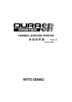
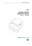
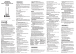
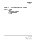
1
♦ PRECISION INSTRUMENTS FOR TEST AND MEASUREMENT ♦
1864-1644
Positive Polarity
Megohmmeter
User and Service Manual
Copyright © 2014 IET Labs, Inc.
Visit www.ietlabs.com for manual revision updates
1864-1644 im/October 2014
IET LABS, INC.
www.ietlabs.com
Email: [email protected]
TEL: (516) 334-5959 • FAX: (516) 334-5988
♦ PRECISION INSTRUMENTS FOR TEST AND MEASUREMENT ♦
IET LABS, INC.
www.ietlabs.com
Email: [email protected]
TEL: (516) 334-5959 • FAX: (516) 334-5988
WARRANTY
We warrant that this product is free from defects in material and workmanship and, when properly used,
will perform in accordance with applicable IET specifications. If within one year after original shipment,
it is found not to meet this standard, it will be repaired or, at the option of IET, replaced at no charge when
returned to IET. Changes in this product not approved by IET or application of voltages or currents greater
than those allowed by the specifications shall void this warranty. IET shall not be liable for any indirect,
special, or consequential damages, even if notice has been given to the possibility of such damages.
THIS WARRANTY IS IN LIEU OF ALL OTHER WARRANTIES, EXPRESSED OR IMPLIED,
INCLUDING BUT NOT LIMITED TO, ANY IMPLIED WARRANTY OF MERCHANTABILITY OR
FITNESS FOR ANY PARTICULAR PURPOSE.
WARNING
OBSERVE ALL SAFETY RULES
WHEN WORKING WITH HIGH VOLTAGES OR LINE VOLTAGES.
Dangerous voltages may be present inside this instrument. Do not open the case
Refer servicing to qualified personnel
HIGH VOLTAGES MAY BE PRESENT AT THE TERMINALS OF THIS INSTRUMENT
WHENEVER HAZARDOUS VOLTAGES (> 45 V) ARE USED, TAKE ALL MEASURES TO
AVOID ACCIDENTAL CONTACT WITH ANY LIVE COMPONENTS.
USE MAXIMUM INSULATION AND MINIMIZE THE USE OF BARE
CONDUCTORS WHEN USING THIS INSTRUMENT.
Use extreme caution when working with bare conductors or bus bars.
WHEN WORKING WITH HIGH VOLTAGES, POST WARNING SIGNS AND
KEEP UNREQUIRED PERSONNEL SAFELY AWAY.
CAUTION
DO NOT APPLY ANY VOLTAGES OR CURRENTS TO THE TERMINALS OF THIS
INSTRUMENT IN EXCESS OF THE MAXIMUM LIMITS INDICATED ON
THE FRONT PANEL OR THE OPERATING GUIDE LABEL.
1864-1644 Positive Polarity Megohmmeter
Contents
Condensed Operating Instructions ..........................................................iv
Specifications.............................................................................................v
1864-1644 Specifications ............................................................................................... v
Chapter 1: INTRODUCTION .......................................................................1
1.1 Description ............................................................................................................... 1
1.2 Opening and Tilting the Cabinet .............................................................................. 1
1.3 Controls, Connectors and Indicators ........................................................................ 1
1.4 Symbols.................................................................................................................... 5
1.5 Connections.............................................................................................................. 5
Chapter 2: INSTALLATION.........................................................................7
2.1 Initial Inspection ...................................................................................................... 7
2.2 Dimensions .............................................................................................................. 7
2.3 Repackaging for Shipment ....................................................................................... 7
2.4 Storage ..................................................................................................................... 8
2.5 Bench Setup ............................................................................................................. 8
2.6 Rack Mounting......................................................................................................... 8
2.7 Power Connections .................................................................................................. 8
Chapter 3: OPERATION .............................................................................9
3.1 Measurement Setup................................................................................................. 9
3.1.1 Ground-Link Connection ............................................................................... 9
3.1.2 Test Voltage Selection .................................................................................... 9
3.1.4 Connection of Unknown ................................................................................ 9
3.2 Measurement Procedure ................................................................................... 10
3.2.1 General ........................................................................................................... 10
3.2.2 Search Procedure ........................................................................................... 10
3.2.3 Sort Procedure ............................................................................................... 10
3.2.4 Shock Hazard ................................................................................................ 10
3.3 Output Jack .............................................................................................................. 11
Chapter 4: APPLICATIONS ........................................................................13
4.1 Insulation Testing ..................................................................................................... 13
4.2 Test Sample Resistivity Measurements.................................................................... 14
4.3.1 General ........................................................................................................... 14
4.3.2 Charging Time Constant ................................................................................ 14
CONTENTS, FIGURES, AND TABLES
i
1864-1644 Positive Polarity Megohmmeter
4.3.3 Measurement Time Constant ......................................................................... 15
4.3.4 Discharge Time .............................................................................................. 15
4.3.5 Large Capacitors, Very High Resistance ....................................................... 15
4.4 Resistance Measurements ........................................................................................ 16
4.5 Measurement of Voltage Coefficient........................................................................ 16
4.6 Guarded 3-Terminal Measurements ......................................................................... 17
4.7 Remote Shielded Measurements .............................................................................. 17
4.8 Measurements Under Humid Conditions................................................................. 17
Chapter 5: THEORY ....................................................................................19
5.1 General .................................................................................................................... 19
5.2 Circuit Description ................................................................................................... 19
5.2.1 General ........................................................................................................... 19
5.2.2 Type 1863 Megohmmeter (Figure 7.6) .......................................................... 19
5.2.3 Type 1864 Megohmmeter (Figure 7.9) .......................................................... 20
Chapter 6: SERVICE AND MAINTENANCE ..............................................21
6.1 Service...................................................................................................................... 21
6.3 Cabinet Removal...................................................................................................... 23
6.4 Troubleshooting ....................................................................................................... 23
6.4.1 General ........................................................................................................... 23
6.4.2 Test Voltages .................................................................................................. 24
6.5 Calibration Procedure .............................................................................................. 24
6.5.1 General ........................................................................................................... 24
6.5.2 Meter Tracking............................................................................................... 24
6.5.3 Voltage Accuracy .................................................................................................. 24
6.5.4 Range-Resistor Accuracy............................................................................... 25
6.5.5 Coarse ∞ Adjustment ..................................................................................... 25
6.6 Knob Removal ......................................................................................................... 26
6.7 Knob Installation...................................................................................................... 27
6.8 Meter Cover Care ..................................................................................................... 27
Chapter 7: PARTS LISTS AND DIAGRAMS ..............................................29
ii
CONTENTS, FIGURES, AND TABLES
1864-1644 Positive Polarity Megohmmeter
Figures
1864-1644 Front-panel Controls, Connectors and Indicators................................. iv
Figure 1-1. Type 1864-1644 Front-panel Controls, Connectors and Indicators ..... 2
Figure 1-2. Type 1864-1644 rear-panel controls and connectors .......................... 4
Figure 1-3. Methods of connection to the measurement terminals ........................ 5
Figure 2-1. Dimensions of the GR/IET 1864-1644 Megohmmeters ...................... 7
Figure 3-1 Ground-link connection to GUARD and to -UNKNOWN terminals ... 9
Figure 4-1. Electrode arrangement for resisitivity measurements ......................... 14
Figure 4.2 Basic megohmmeter circuit ................................................................... 15
Figure 4-3. Guarded measurement of a three-terminal resistor .............................. 16
Figure 5-1 Megohmmeter block diagram ............................................................... 20
Figure 6-1. Connections for measuring standard resistors ..................................... 22
Figure 6-2. Top interior view of 1864 Megohmmeter ........................................... 26
Figure 6-3. Bottom interior view of 1864 Megohmmeter ...................................... 26
Figure 7-1. Replaceable mechanical parts on the 1864-1644 ................................. 31
Figure 7-3. Type 1864 rectifier circuit etched-board assembly .............................. 32
Figure 7-2. Regulator and amplifier circuits etched-board assembly ..................... 32
Figure 7-4 Type 1864 switching diagram ............................................................... 33
Figure 7-5. Type 1864 schematic diagram.............................................................. 34
Figure 7-6. Complete cabinet assembly.................................................................. 35
CONTENTS, FIGURES, AND TABLES
iii
1864-1644 Positive Polarity Megohmmeter
Condensed Operating Instructions
SET ∞
HIGHEST RANGE
GROUND
SET ∞
GUARD
- UNKNOWN +
MULTIPLIER
DIAL
FUNCTION
SWITCH
POWER-OFF
SWITCH
TEST-VOLTAGE
SWITCHES
1864-1644 Front-panel Controls, Connectors and Indicators
1. Determine which ground link connection is to be
used (paragraph 3.1.1 ).
4. Connect the unknown to the UNKNOWN terminals.
2. Set the TEST VOLTAGE switch(es) to the proper
voltage (paragraph 3.1.2).
5. Measure the unknown with either the search (paragraph 3.2.2) or sort (paragraph 3.2.3) procedure.
3. Set the ∞ adjustments (paragraph 3.1.3).
iv
CONTENTS, FIGURES, AND TABLES
1864-1644 Positive Polarity Megohmmeter
Specifications
1864-1644 Specifications
Rmin
Rmax (right end)
Useful
(Full Scale left end) (10% of scale) (2.5% of scale)
Ranges
("0.5" rdg)
("5" rdg)
("20" rdg)
Voltage
Setting
10 Vdc to 50 Vdc
50 kΩ
500 GΩ
2 TΩ*
50 Vdc to 100 Vdc
200 kΩ
5 TΩ
20 TΩ
7
8
100 Vdc to 500 Vdc
500 kΩ
5 TΩ
20 TΩ*
7
500 Vdc to 1090 Vdc
5 MΩ
50 TΩ
200 TΩ
8
*Recommended Limit
Resistance Accuracy (min reading 0.5):
Range 1-5: ±2 (meter reading+1)%
Where meter reading is the actual number
indicated at the scale; e.g. for a reading of
900 kΩ on the 1 GΩ scale, the accuracy is
±2(.9+1)% or 3.8%
Range 6:
Range 7:
Range 8:
add ±2% to accuracy above
add ±3% to accuracy above
add ±5% to accuracy above
Accuracy applies for >100 V;
For ≤100 V add 2%.
Meter Display:
Full mechanical zero at right end, so 2.5 % fullscale is near right end and full-scale is at left end.
However, resistance values read naturally, increasing from left to right.
Short-Circuit Current:
Approximately 5 mA
Power:
100 - 125 or 200 - 250 V
50 - 400 Hz
13 W
Fuse:
For 100 to 125 V operation: 1/4 A
For 200 to 250 V operation: 1/8 A
Fuse holder is located under the IEC receptacle and
holds a 5 x 20 mm fuse.
Dimensions:
6.63 x 10 x 6.75 in.
Weight:
9.5 lb.
Voltage Accuracy (across unknown):
For ≥100 V ± 2%
For <100 V ± (4% + 0.5 V)
CONTENTS, FIGURES, AND TABLES
v
1864-1644 Positive Polarity Megohmmeter
This page intentionally left blank.
vi
CONTENTS, FIGURES, AND TABLES
1864-1644 Positive Polarity Megohmmeter
Chapter 1
INTRODUCTION
WARNING
High voltage is applied to the measurement terminals of
1864-1644 Megohmmeters at all times, except when the
function switch is set to DISCHARGE. While the current
is limited to a value that is not dangerous under most
conditions, the energy stored in a capacitor connected
to the terminals may be LETHAL. Always set the function
switch to DISCHARGE before you connect or disconnect
the unknown.
1.1 Description
1.2 Opening and Tilting the Cabinet
The 1864-1644 (Figure 1-1) indicates resistance
from 50 kΩ to 200 TΩ. These ranges are suitable for
leakage-resistance measurements of most types of
insulation used in electrical instruments, electronic
devices and components, etc (Section 4). The 1864
has a voltage range from 10 to 1090 V that can be set
in 1 Vdc steps from 10 to 109 V, and in 10 V steps
from 100 to 1090 V by using the TEST VOLTAGE
switches on the front panel.
To open the cabinet, refer to the pictorial graphic on
the rear panel of the unit; see Figure 1-2. The Flip-Tilt
cabinet can be opened by placing the instrument on
its rubber feet with the handle away from you. Push
down on the handle and the instrument, located in the
upper part of the case, will rotate to a vertical position.
While holding the handle down with one hand, rotate
the instrument to the desired position with the other
hand and then slowly release the handle.
The 100-volt setting is the EIA standard for measurement of composition, film, and wire-wound resistors
above 100 kilohms. The 500-volt setting is a standard
value in the measurement of the insulation resistance
of rotating machinery, transformers, cables, capacitors, appliances, and other electrical equipment.
A regulated power supply and charging circuit permit rapid and accurate measurement of the leakage
resistance of capacitors.
1.3 Controls, Connectors and Indicators
Figure 1-1 shows the front-panel controls, connectors
and indicators of the 1864. Table 1-1 lists and identifies them. Figure 1-2 shows the rear panel controls and
connectors, and Table 1-2 lists and identifies them.
Guard and ground terminals permit measurement
of grounded or ungrounded two-or three-terminal
resistors.
A panel warning light indicates when voltage is applied to the test terminals and alerts users to the safe
operation of the instrument.
INTRODUCTION
1
1864-1644 Positive Polarity Megohmmeter
3
4
6
5
7
8
2
9
10
1
11
12
Figure 1-1. Type 1864-1644 Front-panel Controls, Connectors and
Indicators
2
INTRODUCTION
1864-1644 Positive Polarity Megohmmeter
Figure 1.1
Reference
Name
Type
Function
1
POWER
OFF
2-position toggle
switch
Turn power on and off.
2
Meter
4-in. meter with
plastic cover
Indicates the value to be
multiplies by the multiplier
switch.
3
SET ∞
HIGHEST RANGE
Knob-rotated
control
Adjusts high end of meter
scale on highest resistance
range to compensate for offset
current.
4
SET ∞
Knob-rotated
control
Adjusts high end of meter
scale on highest resistance
range to compensate for offset
voltage in the voltmeter.
5
GUARD
Insulated binding
post
For guarded measurements. It
can accept a shorting link to
the ground post.
6
Ground
Uninsulated
binding post
Grounds the Unknown- or
guard. Contains a shorting
link.
7
UNKNOWN -
Insulated binding
post
Connects the - side of the
unknown to the megohmmeter.
8
UNKNOWN +
Insulated binding
post
Connects the + side of the
unknown to the megohmmeter.
9
DANGER
Indicated light
shaded red
Glows red when the function
switch is in the CHARGE or
MEASURE position.
10
Multiplier
8-position rotary
switch
Selects resistance range.
11
MEASURE
CHARGE
DISCHARGE
3-position toggle
switch
Selects the operating position
applied to the unknown.
3 rotary switches:
12
TEST VOLTAGE
Select voltage in 1-V steps
from 10 to 109 V and in 100-V
steps from 100 to 1090 V.
INTRODUCTION
10-position
9-position
2-position
3
1864-1644 Positive Polarity Megohmmeter
1
3
2
4
Figure 1-2. Type 1864-1644 rear-panel controls and connectors
Table 1.2.
Figure 1-2
Reference
1
4
Name
Type
Function
Power Input
IEC Standard
Power input
receptacle.
Power input and circuit protection
2
Output
Phone jack
Provides a dc voltage output for recorder
operation
3
Line Voltage
2-position slide
switch
Connects wiring of power transformer for
either 100 to 125 V or 200 to 250 V input
4
1/8 Amp
Integral fuse
holder
Holder for 5 x 20 mm
For 100 to 125 V operation: 1/4 A fuse
For 200 to 250 V operation: 1/8 A fuse
INTRODUCTION
1864-1644 Positive Polarity Megohmmeter
1.4 Symbols
1.5 Connections
These instruments indicate the resistance of the
unknown in multiples of ohms. The relationship
between ohms (Ω), kilohms (kΩ), megohms (MΩ),
gigaohms (GΩ), and teraohms (TΩ) is as follows:
The UNKNOWN, GUARD and ground terminals
are standard 3/4-in. spaced binding posts that accept
banana plugs, standard telephone tips, alligator clips,
crocodile clips, spade terminals and all wire sizes up
to number eleven (Figure 1-3).
1 MΩ= 106 Ω = 103 kΩ
I GΩ= 109 Ω = 106 kΩ= 103 MΩ
1 TΩ = 1012 Ω = 109 kΩ = 106 MΩ= 103GΩ
When several measurements of components with
leads are to be made, consult IET for an appropriate
test jig or fixture.
Figure 1-3. Methods of connection to the measurement terminals
INTRODUCTION
5
1864-1644 Positive Polarity Megohmmeter
This page intentionally left blank.
6
INTRODUCTION
1864-1644 Positive Polarity Megohmmeter
Chapter 2
INSTALLATION
Dimensions in inches
Figure 2-1. Dimensions of the GR/IET 1864-1644 Megohmmeters
2.1 Initial Inspection
2.3 Repackaging for Shipment
IET instruments receive a careful mechanical and
electrical inspection before shipment. Upon receipt,
verify that the contents are intact and as ordered.
The instrument should then be given a visual and
operational inspection.
If the instrument is to be returned to IET Labs, contact
the Service Department at the number or address,
shown on the front cover of this manual, to obtain a
“Returned Material Authorization” (RMA) number
and any special shipping instructions or assistance.
Proceed as follows:
If any shipping damage is found, contact the carrier
and IET Labs. If any operational problems are encountered, contact IET Labs and refer to the warranty
at the beginning of this manual.
Save all original packing material for convenience
in case shipping of the instrument should become
necessary.
1.
2.
3.
4.
2.2 Dimensions
5.
The dimensions of the 1864-1644 are shown in
both the rack and bench-mounted configurations in
Figure 2-1.
INSTALLATION
6.
7.
Attach a tag with the following:
• Owner’s Name
• Model Number
• Serial Number
• RMA Number
Wrap the instrument in heavy paper or
plastic.
Protect the front panel and any other protrusions with cardboard or foam padding.
Place instrument in original container or
equally substantial heavy carton.
Use packing material around all sides of
instrument.
Seal with strong tape or bands.
Mark shipping container “DELICATE INSTRUMENT,” “FRAGILE,” etc.
7
1864-1644 Positive Polarity Megohmmeter
2.4 Storage
2.7 Power Connections
If this instrument is to be stored for any lengthy
period of time, it should be sealed in plastic and
stored in a dry location. It should not be subjected
to temperature extremes beyond the specifications.
Extended exposure to such temperatures can result
in an irreversible change in resistance, and require
recalibration.
The 1864-1644 Megohmmeter can be operated from
either a 100- to 125-V or a 200- to 250-V, 50-to 60Hz power line. Before connecting the 3-wire IEC
power cord to the line, set the slide switch on the rear
panel to the proper setting as indicated by the position
of the white line on the slide switch. The slide can
be actuated with a screwdriver blade. Verify that the
correct size fuse for the input voltage selected has
been installed (1/4 A slow blow for 100-125 V input
or 1/8 A slow blow for 200-250 V input). If it is necessary to use a 3-wire adaptor plug, make certain that
the third wire is connected to a good ground (water
pipe or equivalent). If this is not possible, connect
the panel of the 1864-1644 (uninsulated binding
post) to a good ground. Plug the supplied IEC power
cord into the instrument into a power receptacle. The
power cord may of course be selected to match the
available receptacle.
2.5 Bench Setup
The bench (portable) model of the megohmmeter
is cased in a Flip-Tilt cabinet. The cabinet opens by
pushing down on the handle and tipping the instrument into the desired operating position (paragraph
1.2).
2.6 Rack Mounting
Consult IET Labs.
8
INSTALLATION
1864-1644 Positive Polarity Megohmmeter
Chapter 3
OPERATION
3.1.3 Set ∞ Adjustments
3.1 Measurement Setup
3.1.1 Ground-Link Connection
The grounding link connected to the uninsulated,
grounded, binding post can be connected from this
ground terminal to the GUARD (paragraph 4.6) or
the -UNKNOWN terminal (Figure 31). The ground
link should be connected to the GUARD terminal if
the sample to be measured is a small, separate component, or if it is a component mounted in an enclosure
that should be guarded (see paragraph 4.6). However,
if one terminal of the unknown must be grounded,
then the link should tie the -UNKNOWN terminal
to the instrument case. See Figure 3.1.
-
+
To adjust the SET ∞ controls, proceed as follows:
1. Turn the instrument on.
2. Set the function switch to DISCHARGE.
3. Set the multiplier dial to any range.
4. Make certain that there nothing is connected
to the UNKNOWN terminals.
5. Adjust the SET ∞ control for an ∞ reading
on the meter.
6. Set the multiplier switch to 10-1T
7. Set the function switch to MEASURE.
8. Adjust the SET ∞ HIGHEST RANGE for an
∞ meter reading.
If this adjustment cannot be made electrically, turn
the instrument off, and adjust the mechanical meter
zero adjustment (the center screw on the meter) to
give a meter reading of less than a line width beyond
∞. Repeat steps 1 through 7.
3.1.4 Connection of Unknown
-
+
Small components should be connected directly to
the UNKNOWN terminals. Insulated leads can be
connected to a nearby unknown; however, if the unknown resistance is high, leakage between the leads
will cause a measurement error, and a change in capacitance to the high lead will cause a transient meter
deflection. For such high resistance measurements, a
shielded system is preferable (refer to paragraph 4.7).
Figure 3-1 Ground-link connection to GUARD
terminal (top) and to -UNKNOWN terminal (bottom)
3.1.2 Test Voltage Selection
The TEST VOLTAGE switch(es) should be set to
the desired measurement voltage. The 1864-1644
Megohmmeter has a selection of 10 to 109 Vdc in
1-V steps or 100 to 1090 Vdc in 10-V steps. On the
1864, the right-hand TEST VOLTAGE switch must
be set to the V position for the low voltages and to
the 0 V position for the high voltages.
OPERATION
9
1864-1644 Positive Polarity Megohmmeter
3.2 Measurement Procedure
3.2.1 General
Either of two measurement procedures may be used,
depending on whether or not the correct resistancemultiplier range is known. If the range is not known,
the search procedure (paragraph 3.2.2) should be
followed. If repetitive measurements are to be made
on a given range (i.e., if similar components are to be
sorted) the sort procedure (paragraph 3.2.3) should
be used.
3.2.2 Search Procedure
When the approximate resistance of the sample to be
measured is not known, proceed as follows:
1.
2.
3.
4.
5.
6.
7.
Set the multiplier switch to the lowest range.
Set the function switch to DISCHARGE.
Connect the unknown between the UNKNOWN + and - terminals.
Set the function switch to MEASURE.
Rotate the multiplier switch cw until the
meter gives a reading of less than 5.
The resistance of the unknown is the meter
reading multiplied by the multiplier-switch
indication.
Make measurements towards the low end of
the meter scale whenever possible, for best
accuracy and resolution.
3.2.3 Sort Procedure
When the approximate resistance of the unknown is
known, proceed as follows:
1.
2.
3.
4.
5.
6.
Set the function switch to DISCHARGE.
Set the multiplier switch to the desired
range.
Connect the unknown between the UNKNOWN + and - terminals.
Set the function switch to MEASURE.
The resistance of the unknown is the meter
reading multiplied by the multiplier-switch
indication. For go-no-go checks, it can be
useful to make high-and-low limit lines on
the outside of the meter case with strips of
masking tape.
Make measurements towards the low end of
the meter scale whenever possible, for best
accuracy and resolution.
3.2.4 Shock Hazard
Every precaution has been taken in the design of
1864 Megohmmeters to reduce the possibility of
shock. However, high voltage must be present at
the terminals to make measurements at the required
voltage levels, and the operator should be aware of
the dangers involved.
The current delivered by the megohmmeters under
short-circuit conditions is approximately 5 mA. This
5-mA current is not lethal to most persons but might
be lethal to those with poor hearts, and it is painful to
all. The actual current that will flow through a person
depends on the resistance of the part of the body that
makes contact with the terminals. This resistance can
be as low as 300 Ω. Note that any of the three insulated
binding posts can be at high voltage, depending on
the position of the shorting link.
When capacitors are tested there is an especially dangerous condition because a charged capacitor easily
can have enough energy to cause heart fibrillation
and death. The capacitor should always be shunted
before connection to the megohmmeter, and the function switch should be set to DISCHARGE for a few
seconds before the capacitor is disconnected.
We strongly recommend that additional precautions,
such as rubber gloves and insulated benchtops, chairs
and shoes should be used for anyone making repetitive measurements with the megohmmeter, particularly measurements on capacitors. These precautions
should not take the place of careful discharge of the
capacitors before and after measurement, but should
be used as an additional safety measure.
10
OPERATION
1864-1644 Positive Polarity Megohmmeter
3.3 Output Jack
The OUTPUT jack (J105) on the rear panel makes
accessible a dc voltage that is directly proportional to
the reciprocal of the meter reading, that is, the highest
value is at the 0.5 scale reading and the lowest value
is at ∞. The output voltage for a particular multiplierswitch setting can be calculated by
RRANGE
VOUT = 0.02 x VTEST x
RX
where VTEST is the TEST VOLTAGE setting, RRANGE
is the lower value for a particular multiplier-dial setting (100k for the 1 M/100 k range) and Rx is the value
of the resistance being measured.
The output can be stored in a data file for plotting,
display, or analysis. It can also feed the user’s go/
no-go indicator. The full-scale voltage value for any
test voltage can be calculated from the Vout formula
using 0.5 times the measurement range as the Rx
value. These values are available on the 1864 along
with the other levels that can be set with the variable
TEST VOLTAGE switches (see table 3-1).
OPERATION
11
1864-1644 Positive Polarity Megohmmeter
This page intentionally left blank.
12
OPERATION
1864-1644 Positive Polarity Megohmmeter
Chapter 4
APPLICATIONS
4.1 Insulation Testing
The insulation resistance of electrical machinery,
transducers, etc, is one of several parameters that
may indicate the condition of the insulation. Routine
measurement of capacitance, dissipation factor, and
leakage resistance provides useful data for monitoring the condition of the insulation and for guarding
against incipient breakdown.
A routine test that has been widely adopted for
insulation testing calls for the measurement of the
apparent leakage resistance after a test voltage has
been applied for one minute and again after the test
voltage has been applied for 10 minutes. The ratio
of the indicated resistances, sometimes referred to
as the Polarization Index, can have some relation to
the condition of the Insulation. The results of such
a measurement are apt to be more dependent on the
dielectric absorption of the insulator than on its true
leakage resistance measured at equilibrium. A complete charge-current-vs-time plot will provide more
useful information.
2G
The 1864-1644 Megohmmeters can be used for either true leakage measurements or for measurements
at 1-or 10-minute intervals following the operating
procedure described in Section 3.
MIL-STD-202C gives procedures for insulationresistance measurements of various components.
On large machinery, one terminal must usually be
grounded. The 1864-1644 Megohmmeter is designed
so that the binding post grounding strap should be
connected between the ground terminal and the
-UNKNOWN terminal.
To determine the charge current, divide the test
voltage by the indicated resistance. At the start of
a charge-current-vs-time plot, the meter will be off
scale. The resistance in series with the insulator is
the reading of the upper dial multiplier divided by
500. Table 4-1 lists dial readings and resistor values.
APPLICATIONS
13
1864-1644 Positive Polarity Megohmmeter
WARNING
Capacitors being measured may be charged
and may contain lethal energy. Always set
the function switch to DISCHARGE before
connecting or disconnecting the capacitor
under test.
4.3.2 Charging Time Constant
Figure 4-1. Electrode arrangement for resisitivity
measurements
The time constant for charging a capacitor in the
CHARGE position is determined by the value of
the capacitor times the effective source impedance
of the supply. The supply resistance is approximately,
4.2 Test Sample Resistivity
Measurements
The megohmmeter can be used for measuring the
resistivity of test samples as described by ASTM
Standard D257, which describes in detail the techniques for both surface-and volume-resistivity measurements. The most common electrode arrangement
is that shown in Figure 4.1. In this configuration
surface resistivity is measured with terminal 1 tied
to the -UNKNOWN terminal, terminal 2 tied to
the +UNKNOWN terminal and terminal 3 tied to
GUARD. For volume resistivity measurements,
terminal 1 is tied to the -UNKNOWN terminal,
terminal 2 to the GUARD and terminal 3 to the
+UNKNOWN terminal. The formulas required to
convert from measured resistance to resistivity are
given in the ASTM standard. Contact IET regarding
the availability of resistivity test fixtures.
4.3 Capacitor Insulation Resistance
4.3.1 General
The insulation resistance, IR, of capacitors is measured by either the search or sort method (paragraph
3.2.2 and 3.2.3) used for resistors, except that some
consideration must be given to the charge and discharge currents.
14
E
E
E
R0 = I Ω = 0.005A Ω = 5 kΩ
MAX
where E is the indicated test voltage in volts and IMAX
is the short-circuit current, which is approximately
5 mA. Therefore, the time constant is:
T = R0Cx =
ECX
5000
seconds
where Cx is in μF. As an example, on the 500 V range,
R0 is approximately 100 kΩ so that the time constant
for charging of a 1 μF capacitor is 0.1 s.
The time necessary for full charging depends on the
type of capacitor and the leakage current that is to be
measured. A capacitor with no dielectric absorption
will have a charging current that decreases by a factor
of 2.72 (the natural logarithm to the base e) for every
time constant it is left in the CHARGE position.
Thus,t the effective resistance at any moment is
R0E( R C ) . The capacitor could be considered fully
charged when this resistance is substantially higher
than the true leakage resistance, even though the
charging current theoretically never reaches zero. As
an example a 1 μF capacitor, with a leakage resistance of 1010Ω measured at 500 V, would have less
than 1% error due to charging current, if measured
after seventeen time constants, or 1.7 s.
0
X
APPLICATIONS
1864-1644 Positive Polarity Megohmmeter
Dielectric absorption (dipole and interfacial polarization) is present in many capacitors and insulators,
especially those with a laminated structure. When
voltage is applied to such material, the charge slowly
diffuses throughout the volume and several minutes,
hours, or even days, are required for equilibrium in
order to make the charging current small compared
with the true leakage current. A measure of this effect, called the Polarization Index, is the ratio of the
resistance measured after 10 minutes of charging to
that measured after 1 minute of charging. Often, the
measured resistance after 1 minute of charging is
called the insulation resistance, even though charging current may be much larger than the true leakage
current. (Some capacitor specifications say less than
2 minutes).
4.3.3 Measurement Time Constant
When the function switch is set from the CHARGE
position to the MEASURE position, the standard
resistor is placed in series with the unknown capacitor. If the supply voltage is fixed, the capacitor
must discharge by a voltage equal to that across the
voltmeter at its final reading. The time constant for
this discharge would be CXRs. Because 80% of the
output voltage is fed back to the supply, this time
constant is reduced by a factor of 5. As a result, the
time necessary for an indication, assuming an ideal
capacitor, depends on this time constant or that of
the meter movement, whichever is longer.
4.3.4 Discharge Time
With the function switch set at DISCHARGE, the
UNKNOWN terminals are connected through 470 Ω
and the discharge time is approximately
0.0005 x C μs, where C is in μF. The red DANGER
light is turned off by the function switch, so that the
capacitor might be charged even after the light is
extinguished. However, the discharge time is so short
that this is not a practical consideration, except for
capacitors greater than 100 μF.
Capacitors with high dielectric absorption (paragraph
4.3.2) can have a residual charge even after they are
shunted and must be repeatedly shunted to be completely discharged. Usually this "voltage recovery" is
only a few percent (i.e., 3%) of the original applied
voltage and, therefore, not dangerous to the operator,
but it can cause damage to sensitive circuit elements.
4.3.5 Large Capacitors, Very High
Resistance
Measuring insulation resistance of large capacitors
that have very low leakage is difficult by any method.
Considering the basic circuit of Figure 4.2, if RS is
high, the RS CX time constant can become very long
on the high resistance ranges if CX is large. If RS is
low, the voltmeter must be very sensitive for a given
leakage resistance range and, therefore, the supply voltage (E) must be extremely stable to avoid
large meter fluctuations. The design of the 1864 is
a compromise between these factors. Measurements
become difficult when the RSCX product is 106, even
under ideal conditions. This can be calculated as (CX
in μF) x (RS in MΩ) or (CX in F) x (RS in Ω). Table
4.1 contains values for RS
Measurements can be unsatisfactory even below this
value for an RSCX product for several reasons:
Figure 4.2 Basic megohmmeter circuit
APPLICATIONS
15
1864-1644 Positive Polarity Megohmmeter
1. Dielectric absorbtion. (paragraph 4.3.2). This is
the main cause of erroneous readings. Besides the
difficulty in deciding what charging period should be
used, the previous history of the capacitor will greatly
affect its indicated leakage. For example, if a paper
capacitor is charged to its rated value, discharged for
a short time, and then its leakage current is measured
at some low value, it probably will give a reading
beyond ∞. This is due to voltage recovery that is a
consequence of dielectric absorbtion. The voltage
across the capacitor will increase above the test voltage causing current to flow in the reverse direction.
4.5 Measurement of Voltage Coefficient
2. Temperature coefficient. If the temperature on
the unknown changes and it has an appreciable temperature coefficient, the voltage on the capacitor will
change in the MEASURE position. If RS is large, the
charge (Q) of the capacitor is more-or-less constant,
so if its capacitance changes, its voltage must change
(Q=CV). A temperature-controlled environment is
recommended.
For example, if V1 = 500 V and V2 = 100 V
3. Test voltage changes. The test voltage can have
rapid fluctuations due to large line-voltage transients even though good regulation is provided in
the instrument, because when RSCX is large, the test
voltage fluctuations are transmitted to the voltmeter
unattenuated. This difficulty can be reduced if the
line voltage is regulated. Slow drift of the test voltage can cause erroneous readings if RSCX. is large,
because even a slow drift rate can be fast compared
to the RSCX time constant. A decreasing test voltage
can cause a reading beyond. Sufficient warm-up
time (30 minutes) will allow the temperature inside
the megohmmeter to stabilize and result in a more
constant voltage at the UNKNOWN terminals.
The 1864 Megohmmeter may be used to measure
voltage coefficient as long as its accuracy is adequate.
The voltage coefficient of resistance is defined as:
R1-R2
R2(V1-V2)
x 100%
where V1 > V2
R1 is the resistance at V1, the higher voltage
R2 is the resistance at V2
Voltage coefficient =
R500V-R100V
x
(400)R100V
1
100%
ΔR
%
= 4
R100V
This voltage coefficient is usually negative (except
for reversed semiconductor junctions).
-
4.4 Resistance Measurements
+
The recommended test voltage is 100 V for fixed
composition resistors, film resistors, and wire-wound
resistors above 100 kΩ. (Refer to EIA Standards
RS172, RS196, and REC 229.) These resistors can be
measured easily on the megohmmeter as long as the
accuracy of the instrument is adequate. If the resistors are separate, we suggest that they be measured
ungrounded (with the grounding link connected to
the GUARD terminal).
16
Figure 4-3. Guarded measurement of a three-terminal
resistor
APPLICATIONS
1864-1644 Positive Polarity Megohmmeter
4.6 Guarded 3-Terminal Measurements
In many cases it is necessary to measure the resistance
between two points in the presence of resistance from
each of these points to a third point. This third point
can often be guarded to avoid error caused by the
extraneous resistances.
This situation can be shown diagrammatically as a
three-terminal resistor (Figure 4-3). Here, RX is the
quantity to be measured in the presence of RA and
RB. If the junction of RA and RB is tied to a guard, RA
is placed across the power supply and has no effect
if it is greater than 500 kΩ. RB shunts RS and causes
a much smaller error than that which would be present if no guard were used. The error is approximately
-RS/RB x 100%, where RS equals the value shown in
Table 4-1 for the various ranges. If a choice is possible, the higher of the two stray resistances should
be connected as RB.
The guard terminal can be used whether the GUARD
or the - UNKNOWN terminal is grounded, but note
that if the -UNKNOWN terminal is grounded, the
GUARD terminal will be a high positive voltage
level. Often the terminal to be guarded is a large chassis and it is, therefore, safer to ground the GUARD
terminal. If this third terminal is true ground then the
GUARD terminal must be grounded.
4.8 Measurements Under Humid
Conditions
The 1864 Megohmmeter has been designed to operate
under conditions of high humidity but, nevertheless,
a few simple precautions should be taken to ensure
accurate measurements. These precautions are:
1. Allow several minutes warmup (internal heat
will reduce humidity inside the instrument).
2. Clean the binding-post insulation with a dry,
clean cloth.
3. Use ungrounded operation (tie the GUARD
terminal to the panel ground).
To determine the presence of errors due to humidity,
measure the resistance between the binding posts
with no external connections. Note that with the
-UNKNOWN terminal grounded, breathing on the
terminals will cause a meter deflection because leakage from the insulator of the +UNKNOWN terminal
to the panel is measured.
Actually, this problem is somewhat academic because
the unknown to be measured is usually much more severely affected by humidity than is the megohmmeter.
4.7 Remote Shielded Measurements
Measurements can be made on components that are
some distance from the instrument if care is used to
prevent leakage between the connecting leads and
to avoid the shock hazard. A convenient way to do
this is to use a shielded cable. If the unknown can
be measured ungrounded, make the connection to
the +UNKNOWN terminal with the shielded lead,
tie the shield to the GUARD terminal, and connect
the GUARD terminal to the panel ground with the
connecting link. If one side of the unknown must
be grounded, connect the grounding link to the
+UNKNOWN terminal, shield the +UNKNOWN
terminal, and tie the shield to the GUARD terminal.
In this instance, the shield is not at ground potential
and should be insulated.
APPLICATIONS
17
1864-1644 Positive Polarity Megohmmeter
This page intentionally left blank.
18
APPLICATIONS
1864-1644 Positive Polarity Megohmmeter
Chapter 5
THEORY
5.1 General
The 1864 Megohmmeter basically consists of a regulated dc power supply, a set of precision resistors,
and a FET-input voltmeter (Figure 5.1). Switch S1 is
closed in the DISCHARGE position of the function
switch and open in the CHARGE and MEASURE
positions, while S2 is open only in the MEASURE
position.
The regulated voltage, E, is controlled by a resistance
RA. A meter sensitivity resistor, RB , is ganged to the
voltage control resistor, RA, to make the meter reading independent of applied voltage, (assuming that
the unknown has no voltage coefficient). An inverse
scale is used on a reversed meter to give a reading
proportional to RX (and not its reciprocal) and yet
have a scale that increases from left to right (0 to ∞).
Metal-film standard resistors are used on all ranges.
The top range of each instrument uses feedback to
effectively multiply the value of the previous standard resistor by a factor of ten. In the 1864 the 2 GΩ
resistor is multiplied to 20 GΩ. The specifications are
again broadened to allow for the tolerance variations
of this multiplication.
The voltmeter uses a FET-input, four-stage, unity-gain
amplifier (AMP, Figure 5.2) to obtain high stability
and low drift. The SET ∞ control on both instruments
is a voltage balance control, while the SET ∞ HIGHEST RANGE control compensates for the FET gate
current on the highest ranges.
5.2 Circuit Description
5.2.2 Type 1863 Megohmmeter (Figure 7.6)
The voltage supply section (RECT.) of the 1863
consists of five different circuits, three dc and two ac.
One ac circuit is a voltage source for the three pilot
lamps used, two to indicate the measurement range
(P101, P102) and the third to light the DANGER
indicator (P103). The second supplies filament voltage to the vacuum tube V101.
The first dc supply is a half-wave rectifier circuit
with a 24-V Zener diode (CR 111) that supplies
voltages to the amplifier (AMP) circuit. A second dc
supply is a voltage doubler (CR101-CR104, C101C102) that supplies the plate voltage to V101. The
voltage to the plate is the same for the 50- to 250-V
ranges but R109 is eliminated from the circuit for the
500 V range. The third dc supply is a half-wave
rectifier with a 20-V Zener diode (CR211) to supply
voltage levels to run the unity-gain amplifier (+1).
Tube V101 is a series regulator that is controlled by
the 5.6 V Zener diode (CR112, REF) and the setting
of R140.The voltage picked off R 140 is fed into
one side (Q102) of the differential amplifier (Q102,
Q103) while part of the output voltage is fed into the
other side (Q103). The output of the amplifier is fed
to the base of Q101 (AMP) and then to the grid of
V101 for controlling the output voltage.
The output selection resistors are R124 through
R133. These resistors determine the TEST VOLTAGE level. Resistors R211 through R219 are the
standard resistors (RS) that determine the measurement range. The output from this circuit is fed
through the SET ∞ HIGHEST RANGE control
(R241) to the FET amplifier.
5.2.1 General
The following paragraphs will relate specific components from the schematic diagrams of the 1863
(Figure 7.6) and 1864 (Figure 7.9) to the general
components shown in Figure 5.1.
THEORY
19
1864-1644 Positive Polarity Megohmmeter
Figure 5-1 Megohmmeter block diagram
A unity-gain FET-input amplifier (+1) follows the
standard resistors in the circuit configuration. R210
and C203 comprise a low-pass filter input to FET
Q204. The amplifier components include a differential amplifier (Q202, Q203), a coarse ∞ control
(R244), the SET ∞ control (R242) and an output
transistor (Q201). The signal then enters the series
combination of R135 and R134 back to the GUARD
terminal.
Resistors R221 through R223 (RB) are meter-sensitivity resistors that are ganged to the voltage resistors
R124 through R127 (RA). R222 is used for both the
50 V and 500 V ranges, while the 200 V range uses
the circuit resistance and has no added resistor. The
remaining two resistors, R221 and R223, are used
for the 250 and 100V ranges, respectively. Potentiometer R243 is an adjustable control in the meter
sensitivity circuit.
20
5.2.3 Type 1864 Megohmmeter (Figure 7.9)
The circuit of the 1864 Megohmmeter is basically
the same as that of the 1863 (paragraph 5.2.2). The
exceptions are explained in the following paragraphs.
In the 1864 the second dc power supply is a quadrupler. This supply establishes the plate voltage of
V101 with the use of resistors R109 through R114.
The regulator circuit has a slightly different input
when the TEST VOLTAGE switch is switched
from V (1) to 0 V (10). Resistors R124 and R125 are
switched out of the circuit in the 0V (10) position.
Voltage-selection resistors for the 1864 are R126
through R133 and the meter sensitivity resistors are
R221 through R228. An additional range resistor,
R220, is in the 1864.
THEORY
1864-1644 Positive Polarity Megohmmeter
Chapter 6
SERVICE AND MAINTENANCE
WARNING
Dangerous voltages are present inside this case. When
troubleshooting, a ground strap should be connected
between GUARD and GROUND on panel to keep the
subpanel (Guard) at ground potential. Refer all servicing to qualified service
personnel.
6.1 Service
The warranty attests the quality of materials and
workmanship in our products. When difficulties do
occur, our service engineers will assist in any way
possible. If the difficulty cannot be eliminated by
use of the following service instructions, please write
or phone our Service Department (see last page of
manual), giving full information of the trouble and of
steps taken to remedy it. Be sure to mention the type,
ID, and serial numbers of the instrument.
Before returning an instrument to IET for service,
please phone or e-mail to our Service Department,
requesting a “Returned Material Authorization
Number.” and instructions for return.
6.2 Minimum Performance Standards
The following checks are provided for verifying the
performance of the 1863 and 1864 Megohmmeters.
The test equipment necessary to perform these checks
is listed in Table 6.1. To check an instrument, proceed
as follows:
(1-13: meter tracking check)
(14-19 voltage accuracy check)
1. Connect the case to the GUARD terminal with
the shorting link.
2. Set the decade resistor to 0500000
(500 kΩ).
3. Set the TEST VOLTAGE switch to to 1-0-0V.
4. Set the multiplier switch to 1 M.
5. Set the POWER/OFF switch to POWER.
6. Adjust the two SET ∞ controls as described
in Section 3.
7. Connect the Decade Resistor to the
UNKNOWN terminals with the dual
banana plug patch cord.
8.Set the function switch to MEASURE.
9. Read the panel meter.
The reading should be 0.5 ±3%,
that is, ±2 (1 + meter reading)%
or 2 (1 + 0.5) = 3%.
10. Set the decade resistor to 1,000,000
(1 MΩ).
The meter should read 1 ±4%.
11. Set the decade resistor to 5000000
(5 MΩ)
The meter should read 5 ± 12%.
12. Set the TEST VOLTAGE switch to 10 V.
13. Set decades to 5,000,000 (5 MΩ) and the
MULTIPLIER to 10M.
The meter should read 0.5 ± 3%.
14. Increase the voltage to 20 V.
The meter reading should remain at
0.5 ±3%.
15. Continue to increase the voltage settings and
observe that the meter reading remains
at 0.5 ±3%.
NOTE
When the light under the 1 M on the multiplier
switch goes out, the switch must be rotated so
that the 1 M on the adjacent scale is lighted.
SERVICE AND MAINTENANCE
21
1864-1644 Positive Polarity Megohmmeter
16. Set the POWER/OFF switch to OFF and
disconnect the decade resistor.
17. Connect the Digital Multimeter between the
GUARD and -UNKNOWN terminals
with two single banana plug patch
cords.
18. Connect the two ground terminals together
with a third patch cord (Figure 6.1).
The megohmmeter shorting link
should remain attached only to the
ground terminal.
19. Set the multiplier switch in the full ccw position (1M, 100k) and the function switch
to MEASURE.
20. Measure the various standard resistors of the
megohmmeter with the DMM according
to the settings and tolerances of Table
6.2. Use the IET LOM-510A megohmmeter for resistance values beyond the
range of the DMM.
22
-
+
Figure 6-1. Connections for measuring standard
resistors with a digital multimeter
SERVICE AND MAINTENANCE
1864-1644 Positive Polarity Megohmmeter
6.3 Cabinet Removal
To remove the instrument from the cabinet, remove
the two screws on the rear of the instrument cabinet
and pull the instrument out of the cabinet.
Warning
Be careful when troubleshooting the instrument
when it is out of its cabinet and connected to
the power line. Dangerous voltages are present,
particularly at the transformer terminals. Connect the shorting link between the GUARD and
ground terminals to keep the voltmeter circuitry
near ground potential.
* Voltages are dc and the values are typical. Set TEST VOLTAGE
switch to 200, function switch to CHARGE, connect the shorting link
between the ground terminal and GUARD, and set the mulitplier
switch to 1 M. Measurements made with 1863 line voltage set at 115
Vac.
6.4 Troubleshooting
6.4.1 General
The following information is designed to assist in
troubleshooting the 1863 and 1864 Megohmmeters.
An understanding of the theory involved in these
instruments (Section 5) makes the instrument easy to
analyze because the problem can usually be located
quickly in either the voltage regulator or in the meter
circuit.
† This value only appears as a fixed resistor in the 1864. Since the value is determined by
feedback multiplication of the 200-M Ω resistor in the 1863, no measurement should be made
with the mogohm bridge.
*This range only appears on the 1864. Its range value is determined from the feedback multiplication of the 2-G Ω resistor, therefore, no mesurement should be made with the megohm
bridge.
SERVICE AND MAINTENANCE
23
1864-1644 Positive Polarity Megohmmeter
If the instrument is completely inoperative, be sure to
check the power-line connection and the fuse (located
in the IEC power input assembly on the rear panel).
6.4.2 Test Voltages
Tables 6.3 and 6.4 list a number of typical test voltages
to assist in trouble analysis. Figures 6.2 through 6.5
and the diagrams of Section 7 will assist in locating
components for testing purposes.
6.5 Calibration Procedure
6.5.1 General
The accuracy of the 1863 and 1864 depends on the
accuracy of the range resistors, the accuracy of the
applied voltages and the meter tracking accuracy.
The over-all accuracy can be checked most easily by
checking each one of these contributing quantities
separately, for to check all points on all ranges at
all voltages would require a tremendous number of
measurements.
6.5.2 Meter Tracking
The scale tracking can be easily checked using a decade resistance decade box with 100-kΩ and 1-MΩ
steps. Steps a through m of paragraph 6.2 should be
performed to check the tracking. If all readings are
corrected by the amount of the error found at a reading of 0.5 they should be better than the specification.
6.5.3 Voltage Accuracy
While the voltage can be checked to be within its
specification, a more important check is to see that
the voltage and meter sensitivity track to give a correct resistance reading. Such a check is generally
adequate for it would be an unusual coincidence if
both the voltage-control and meter-sensitivity resistors were in error, such that a good reading is obtained.
To check this tracking, perform steps n through s of
paragraph 6.2. If a reading is incorrect, the voltages
should be checked with a DMM connected between
the +UNKNOWN and -UNKNOWN terminals. The
function switch can be set to either the CHARGE or
MEASURE positions.
24
SERVICE AND MAINTENANCE
1864-1644 Positive Polarity Megohmmeter
If all the voltages are out of tolerance in the same
direction, they can be set within the tolerance by
adjusting R140 located on etched-circuit board P/N
1864-2701 (common to both the 1863 and 1864 Megohmmeters and shown in both Figures 6.2 and 6.4).
The adjustment can be made as soon as the instrument is removed from the cabinet (paragraph 6.3). It
is not necessary to move either of the printed-circuit
boards, since the adjustment is on the top printedcircuit board. This adjustment affects all voltages by
the same amount, but adjustment at 200 V minimizes
possible errors due to resistance tolerances.
If all the voltages are correct but all meter readings
are in error in the same direction, the meter sensitivity can be reset. Adjust R243 (Figures 6-2 and 6-4),
located on the same etched-circuit board as R 140,
to correct the meter readings. This adjustment affects
ail measurements but on the 1863 is most sensitive
at 200-V and 250-V and least sensitive at 100 V.
In the 1864, it is most sensitive at the lower settings of the first digit of the test voltage adjustment,
i.e. 100 V, 200 V, etc.
6.5.4 Range-Resistor Accuracy
The range resistors can be checked by performing
procedure steps in of section 6.2.
6.5.5 Coarse ∞ Adjustment
If it is impossible to set the infinity controls on the
front panel, set both controls at their center positions
and adjust R244 (Figures 6-2 and 6-4), located on
the etched-circuit board with R140, for a reading as
close to ∞ as possible. Make the final adjustments
with the front-panel controls.
SERVICE AND MAINTENANCE
25
1864-1644 Positive Polarity Megohmmeter
6.6 Knob Removal
If it should be necessary to remove the knob on a
front-panel control, either to replace one that has
been damaged or to replace the associated control,
proceed as follows:
1.
1. Grasp the knob firmly with the fingers,
close into the panel (or the indicator dial, if
applicable), and pull the knob straight away
from the panel.
CAUTION
Do not pull on the dial to remove a dial/knob assembly. Always remove the knob first. To avoid
damage to the knob and other parts of the control,
do not pry the knob loose with a screwdriver or
similar flat tool, and do not attempt to twist the
Knob from the dial.
Figure 6-2. Top interior view of 1864 Megohmmeter
2. Observe the position of the setscrew in the
bushing, with respect to any panel
markings (or at the full ccw position of
a continuous control).
3. Release the setscrew and pull the bushing
off the shaft.
4. Remove and retain the black nylon thrust
washer,
NOTE
To separate the bushing from the knob, if for any
reason they should be combined off the instrument, drive a machine tap a turn or two into the
bushing for a sufficient grip for easy separation.
Figure 6-3. Bottom interior view of 1864
Megohmmeter
* or any commercial equivalent
26
SERVICE AND MAINTENANCE
1864-1644 Positive Polarity Megohmmeter
6.7 Knob Installation
To install a knob assembly on the control shaft:
1.
Place the black nylon thrust washer over the
control shaft, if appropriate.
2. Mount the bushing on the shaft, using a small
slotted piece of wrapping paper as a shim for
adequate panel clearance.
3. Orient the setscrew on the bushing with
respect to the panel-marking index and lock
the setscrew with the appropriate hex-socket
key wrench.
NOTE
Make sure that the end of the shaft does not
protrude through the bushing or the knob won’t
bottom properly.
It is treated inside and out in manufacturing with a
special non-abrasive anti-static solution, Statnul*,
which normally should preclude any interference in
meter operation caused by electrostatic effects. The
problem is evidenced by the inability of the meter
movement to return promptly to a zero reading, once it
is deenergized. As supplied by IET, the meter should
return to zero reading within 30 seconds, immediately
following the placement of a static charge, as by rubbing the outside surface. This meets the requirements
of ANSI standard C39.1-1972.
If static-charge problems occur, possibly as the result
of frequent cleaning the window should be carefully
polished with a soft dry cloth, such as cheesecloth or
nylon chiffon. Then, a coating of Statnul should be
applied with the polishing cloth.
CAUTION
4.
4. Place the knob on the bushing with the
retention spring opposite the setscrew.
5. 5. Push the knob in until it bottoms and pull
it slightly to check that the retention spring is
seated in the groove in the bushing.
NOTE
If the retention spring in the knob comes loose,
reinstall it in the interior notch that has the thin
slit in the side wall. It will not mount in the
other notch.
6.8 Meter Cover Care
The clear acrylic meter cover can become susceptible
to electrostatic-charge buildup, and can be scratched
if improperly cleaned.
Do not use any kind of solvent. Tissues or paper
towels can scratch the window surface.
If it should be necessary to place limit marks on the
meter window, paper-based masking tape is recommended, rather than any kind of marking pen, which
could be abrasive or react chemically with the acrylic.
NOTE
Electrical parts information in this section is presented in such a way that all the data for a part-numbered
sub-assembly are visible together in the manual.
Thus, the parts list appears on left-hand pages, while
the part-location diagram (on the apron) and the
schematic diagram (tip out) are on right-hand pages.
REFERENCE DESIGNATOR ABBREVIATIONS
B
BT
C
CR
DS
F
J
K
KL
KS
L
M
MK
= Motor
= Battery
= Capacitor
= Diode
= Lamp
= Fuse
= Jack
= Relay
= Relay Coil
= Relay Switch
= Inductor
= Meter
= Microphone
P
Q
R
S
T
U
VR
X
Y
Z
= Plug
= Transistor
= Resistor
= Switch
= Transformer
= Integrated Circuit
= Diode, Zener
= Socket for Plug-In
= Crystal
= Network
SERVICE AND MAINTENANCE
27
1864-1644 Positive Polarity Megohmmeter
This page intentionally left blank.
28
SERVICE AND MAINTENANCE
1864-1644 Positive Polarity Megohmmeter
Chapter 7
PARTS LISTS AND DIAGRAMS
ELECTRICAL PARTS LIST
1864 CHASSIS
c
~OUNTED
DES CRI PTION
REFDES
PART
PARTS
NO.
FMC
MFGR
PAR T
NUI-'BER
CAP MYLAR .047UF 10 PCT 1000V
CAP CER ~Q
o10UF 80/20PCT lOOV
CAP CER DISC 6800PF 20PCT 1.4KV
4860-8255
440 3-4 100
4406-2689
75042
72 982
72982
6 63UW .047 UF 10PC T
8l3 1Ml 006 51104Z
848 - Z5U -68 00PF20PCT
CR 106
CR 107
CP. 108
RECT 1N4005 600PIV .75A Sl
RECT 1N4005 600PIV .75A Sl
DIODE RECTIFIER 1N4003
6081-1003
6081-1003
6081-1001
1443 3
14433
14433
1N4005
1N4005
1N4003
F
F
101
102
FUSE SLO-BLOW l/8A
FUSE SL0-8LOW 1/16A
5330- 0450
5330-0300
75915
75915
313 .125
313 .0 62
J
J
J
J
J
101
102
l 03
104
1 05
BINDING POST ASM
B INDING PO ST ASM
BINDING POS T ASM
B I"--DING POST ASM
PHONE IN S .2 8 1L 2 C KT
093B- 3003
0938-3022
0938-3003
0938-3003
4260-10 3 1
24655
246 55
24655
2 4655
82389
09 3 8-3 0J3
0938-3022
0938- 3003
0938-3003
N-111
M
101
METER
5730-1412
24655
5730-141 2
p
p
101
1 02
103
LAMP FLANGE BASE 6V Oo2A lOOOH
LAMP FLANGE BASE 6V 0.2A lO OOH
LAMP FLANGE BASE 6V .04A 10000H
5600-0300
5600-0300
5600-0316
71744
7 1 744
71744
CM-328
CM-328
CM-345
CORD 3 WR
c
c
p
110
111
113
PL 501
A50A
A50A
250V
250V
4200-1800
2465'5
4200-1800
1 09
110
111
112
113
114
115
116
124
1 25
126
127
1 28
1 29
130
131
132
1 33
137
1 '<1
2 11
2 12
213
2 14
2 15
216
21 7
2ld
219
2 20
22 1
222
223
22 4
225
226
22 7
228
241
242
2'<5
RES COMP
62 K
5PCT lW
R~S
COMP
68 K 5 PCT 1W
RES COMP 270 K
5PCT lW
RES COMP 120 K
5PCT l/2W
RES COMP 390 K 5PCT 1/2W
RES COMP 1.2 M 5PCT l/2W
RES COMP
39 K 5PCT 1W
RES COMP
47 K
5PCT 2W
RES FLM
226K
1/2PCT 1/8W
RES COMP
30 K O HM
5PCT 1/2W 0
RES F LM 49 9K
1/2 PCT l/4W
RES FLM 1M
1/ 2 PCT 1/2W
RES FLM 2 M
1/ 2 PCT 1/2W
R ES F LM 2M
l/ 2 PCT 1/2W
RES F LM 49. 9 K
1/2 PCT l/4W
kES FLM lOOK
1 PCT l/4W
RES FLM 200K
1 PCT l/4W
RE S FLM 200K
1 PCT 1/4W
R~S COMP
11
OHM
5PCT l/2W 0
R ES COMP
30 K OHM
5PCT 1/4W D
RES FLM l OOK
1 PCT
1/ BW
RES FLM llK
1 PCT
l/ 8 W
RE S FL M 1 .0 2 M 1 PCT 1/2W
RES FLM
2K
1/ 2 PCT 1/ 8 W
RFS FLM 20K
1 PCT 1/2W
RES FLM 200K
1 PCT 1W
RES FLM 2M
1 PCT 1/2W
RES FLM 20M
1 P CT 1W
RES FLM 200M
lPCT
100PPM
1W
RES FILM CAR BON 2G. OHM 1 PCT
RES FLM 1.91K
1/2 PCT 1/4W
RES FLM 3 . 83K
l/2 PC T l /4W
RES FLM 7.68K
1/2 PCT 1/4W
RES F LM 7.6 8 K
1/2 PCT 1/4W
R ~ S FLM 200 OHM
1 PCT 1/ 4 w
RES FLM 40 2 OHM
1 PCT
1/ 8 W
R ES FLM 806 OHM
1 P CT 1/ 4 W
1 PCT 1 /4\ol
R E S F LM 806 OHM
P OT COMP KNOB
1K OHM 10 PCT LIN
POT COMP KNOB 2 .5K OHM 10PCT LIN
RES WW AX L E AD 5.1K OHM 5PC T 3 W
611 0-3625
611 0-3 6 85
6110-4 2 75
6100-4125
6100-4395
6100-5125
6110-3395
6120-3475
6251-3226
6100-33 05
6351-3499
6451-4100
6 451-4 200
6451-4 20 0
6351-2499
6350-3100
6350-3200
6350-3200
6100-0115
609'>-3305
6250-3100
6250-2110
6450-4102
6251 -12 00
6450-2200
6550-32 00
6450-4200
6550- 520 0
6619-3407
6740-1504
6351-1191
6351-1383
635 1-176 8
6351-1768
6350-0200
6250-0402
6350-0806
6350 - 080b
6 000-0300
6000-0400
6680-2515
81349
81349
81349
81349
81349
81349
81349
81349
8 1349
81349
8 134S
8 1349
8 1349
813 4 9
81349
81349
81349
81349
81349
813 4 9
B1349
8 134 9
81349
8 1349
8 1349
81349
8 1.349
81 349
24655
63060
81349
813 49
81349
81349
8134'>
8 1349
81 3 49
8 1 349
01121
0 11 2 1
7 5042
RCR32G623J
RC R.32G683 J
P.CR32G274J
RCI>.20G124J
'\CR20G394J
RCR20G12 5 J
RCR32G5 93 J
RCR42G47 3 J
RN55CZ263C
RCR 20G303 J
RN6004 993D
RN6501 004 0
RN65 02004D
RN650 20040
RN6004992D
P.N6001003F
RN6002 003 F
RN600200 3 F
RCR20G110J
I>.CR07G 303 J
RN5501003F
RN55Dl10 2 F
RN6501024F
RN55D2001D
RN65D2002F
RN 750 2003F
RN65D2004 F
RN7502005F
6619-3407
RX-1
RN6001911D
RN6003831D
RN60D7681D
RN60076 8 10
RN6002000F
RN5504 020F
RN6008060F
RN6008060F
JAIN056Sl02 UZ
JAIN0 565252 UZ
AS-2 5 .1 K 5PCT
s
101
102
10 3
20 1
202
50 1
50 2
S WITCH
SWITCH
SWITCH
SW IT C H
Sw i TC H
S WITC H
SWITCH
7890-5350
7 890-536 0
78 '>0-53 7 0
7890- 5380
1 8 64-040 0
791 0 -1 300
7910- 08 32
2 4 655
24655
24655
2 465 5
2465 5
04 009
82389
7890- 5350
7890-536 0
78 90- 5370
7 890-5380
1 8 64- 0400
83053
11A-1266
T
101
T R ANSFO~M E R
0345 -4028
24655
0345-4028
R
R
R
R
R
R
R
R
R
R
R.
R
R
R
R
R
R
R
R
R
R
R
R
R
P.
R
R
R
R
R
R
R
R
R
R
R
R
R
R
R
R
s
s
s
s
s
s
l OA 120V US 7FT HAMMER
RO TARY ASM
ROTARY AS M
ROTARY ASM
ROTA RY ASM
ASM
TOGGL E 2 P OS DPST STE ADY
S LID E 2 POS DPDT STE ADY S
PO WER
PARTS LIST AND DIAGRAMS
29
1864-1644 Positive Polarity Megohmmeter
ELECTRICAL PARTS LIST
REGULATOR
REFOES
& A~PLIFIER
107
108
l C9
201
202
203
CAP
CAP
CAP
CAP
CAP
CAP
CR
CR
CR
CR
' CR
CR
105
l 11
112
201
211
212
CIODE
ZENER
lEN E R
DIODE
l ENE R
ZENER
Q
Q
Q
101
102
103
201
2 02
203
204
205
206
TRANSISTCR 2N3903
TRANSiSTOR 2N4250
TRANSISTCR 2N4250
TRANSISTCR 2N3903
TRANSISTOR 2N3905
TRANSISTCR 2N3905
TRANSISlORISTATIC PRCTECT
TRANSISTCR MPS-A14
TRANSISTCR 2N3414
107
108
117
118
119
120
121
122
123
134
135
138
139
140
201
202
203
204
205
206
2 07
208
209
210
229
230
Q
Q
Q
Q
Q
Q
R
R
R
R
R
R
R
R
R
R
R
R
R
R
R
R
232
234
2.35
2 36
237
238
239
243
2 44
RES
RES
RES
RES
RES
RES
RES
RES
RES
RES
RES
RES
RES
POT
RES
RES
RE S
RES
RES
RES
RES
RES
RES
RES
RES
RES
RES
RES
RES
IHS
RES
RES
RES
RES
POT
POT
V
101
TUBE
R
R
R
R
R
R
R
R
R
R
R
R
R
R
R
R
R
R
R
R
2~1
PART
DESCRIPTION
c
c
c
c
c
c
ALLM 30 UF 75V
CER C ISC .OlUF 80/20PC T 100V
CER CISC
100PF
5PCT SOOV
ALUt" 30 Uf 75V
CER CISC .01UF 80/20PCT 100V
MICA 1uvPF 10PCT SOOV
RECTIFIER lN4003
1N'i708
24V
5 PC T
1N 1!: 3A
6.2V
5PCT
RECTIFIER 1N4003
1 N <; 6 e B
20 V
5PCT
1NG658
15V
5PCT
.4W
.4W
.4W
.4W
RE~l
COMP 2.0 K OHM
5PCT 1/2W
CCMP 1.0 K 5PCT 1/2W
CCMP ~20 OH~
5PCT 1/2W
CCMP 200 K OHM
5PCT l/2W
CCMP
12 K
5PCT 1/2w
COMP 8.2 K
5PCT l/2W
CCMP
10 K
5PC1 l/2W
COMP
10 K
5PCT 1/2W
FLM 24.9K
l/2PCT l/8W
CCMP
68 K 5PCT l/2W
CCMP
16 K OHM
5PCT 112W
C CMP
22 K
5 PC T 1 I 2 W
FLM 200K
1 PCT 1/4W
WW TRM
5K OHM 10 PCT 1T
CCMP 1.2 K
5PCT 1/2W
C CMP 2 • 7 K 5 PC T 1/ 2 w
COMP
27 K
5PCT l/21.
CCMP
43 K OHM
5PCT li2W
COMP .3.3 K
5PCT 1/2W
COMP
10 K
5PCT l/2W
CCMP
24 K CHM
5PCI 1/2W
COMP
20 K OHM
5PCT 1/2w
CCMP
47 M 5PCT l/2W
CCMP
47 M 5PCT li2W
COMP 1.2 K
5PCT l/2W
CCMP 100 K
5PCT l/2W
CCMP 1.0 M 5PCT 1/2 W
COMP
10 M 5PCT l/2W
CCMP
10 K 5PCT l/4W
COMP 100 OHM
5PCT 1 /4W
CCMP 2.4 M OHM
5PCT 1/2W
CCMP 2 .4 M CHM
5PCT 1/ 2 W
COMP 2.4 M OHM
5PCT l/2W
CCMP 2.4 M OHM
5PCT l/2W
1\W TR/J, 500 OHM 10 PCT 1T
WW TRI~
5K OHI~ 10 PC T 1 T
~ACLUM
6AB4
P/N 1864-2701
PC BOARD
NO.
FMC
MFGR
PART
NUMBER
445 J-6113
't40 1-310J
440 4-110 5
4450-6173
4401-3100
4620-1000
56289
72982
72982
56289
72982
81349
43 D30J GO 75
0805540Z5 U00103Z
U831082Z5000101J
430300G075
0805540Z5U00103Z
CM15F0101K
6081-1001
6083-1054
6083-1006
6081-1001
6083-1018
6083-1015
14433
14433
14433
14433
14433
14433
1N4003
IN970B
I N753 A
1N4003
IN968B
IN965B
8210-1132
8210-1294
8210-1294
8210-1132
821D-1114
8210-1114
8210-1143
821D-1246
82l0-129v
04713
07263
07263
04 713
04713
04713
04 71.3
04713
56289
2N3903
2N42 50
2N4250
2N3903
2 N3 905
2N3905
2N4220
MPS-A14
2N3414
610Q-2205
6100-2105
6100-1225
610Q-4205
6100-3125
6100-2825
6lOD-3105
6100-3105
6251-2249
6100-3685
6100-3165
6l0Q-3225
6350-3200
6056-0142
6l.OD-2125
6100-2275
61.00-32"75
6100-3435
6100-2335
6100-3105
6100-3245
6100-3205
610Q-6475
6100-6475
6100-21.25
6100-4105
6100-51\.)5
6100-6 105
6J99-3105
6J99-ll05
610Q-5245
6100-5245
6lOQ-52 4 5
6100-524 5
6056 - 0136
6056--014 2
81349
81349
81349
81349
81349
81349
81349
81349
81349
81349
81349
81349
81349
24655
81349
81349
81349
8134<)
81349
81349
81349
81349
81349
81349
81349
81349
81349
81349
81349
81349
81349
81349
81349
81349
24655
24655
RCR20G202J
RCR 20G 102J
RCR20G221J
RCR20G204J
RCR2JG123J
RCR20G822J
RCR 20G 1 03J
RCR2JG103J
RN5502492 0
RCR20G683J
RCR20G163J
RCR20G223J
RN6002003F
6056-0142
RCR20G 122J
RCR20G272J
RCR2 OG2 73 J
RCR 20G 433J
RCR20G332J
RCR20Gl03 J
RCR20G243J
RCR2uG203J
RCR20G476J
RCR20G4 76J
RCR20G122J
RCR2 OG 1 04J
RCR20G105J
RCR2 OG1 06 J
RCR07G 103J
RCRu7G101J
RCR20G245J
RCR20G245J
RCR20G245J
RCR20G245J
6056-0136
6056-0142
8360-0100
79089
6AB4
PARTS LIST AND DIAGRAMS
30
1864-1644 Positive Polarity Megohmmeter
3
4
5
2
6
7
1
8
10
9
Figure 7-1. Replaceable mechanical parts on the 1864-1644
Replaceable parts list
Model Ref
1
2
3
4
5
6
7
8
9
10
IET Pt No
7910-1300-02
Description
Power switch
5730-1412-01
Meter assembly
5520-5220-AS
Knob assembly for 1863/64 potentiometers
3770-2
Red binding post
01-1008-1-0310
Gold binding post
1864-1200
Dial assembly
1864-0400
Measure-Charge-Discharge switch
1864-1220
Dial assembly for 1864 voltage range
1864-1230
Dial assembly for 1864 voltage setting B
1864-1210
Dial assembly for 1864 voltage setting A
PARTS LIST AND DIAGRAMS
31
1864-1644 Positive Polarity Megohmmeter
Figure 7-2. Regulator and amplifier circuits etched-board assembly
Figure 7-3. Type 1864 rectifier circuit etched-board assembly (P/N 1864-2720)
PARTS LIST AND DIAGRAMS
32
PARTS LIST AND DIAGRAMS
Rotary switch Sections are shown as viewed
from the panel end of the shaft. The first digit
of the contact number refers to the section.
The section nearest the panel is 1, the next
section back is 2, etc. The next two digits refer
to the contact. Contact 01 is the first position
clockwise from a strut screw (usually the screw
above the locating key), and the other contacts
are numbered sequentially (02, 03 1 04, etc),
proceeding clockwise around the section. A
suffix F or R indicates that the contact is on
the front ~r rear of the section, respectively.
5101,
5102,
2051'<
WH-~ol;r
Pl02
ONE
r~H
WH -RO·BU
VT- RO
JIOI,
311F
~
105FI
WH.YT BK
........._____
:~~
I04F(f
\
2W
I
109F
Y~ ~RI24
[J.._h~-1~; 1~~~·
102F
211F
l~
•IOIF
211r
..-v-· v 20 .,
~9 "'CRI07
~ 0(
~St.
;/204R
~~-~:_ __ ____.. S103,!06F
WH-GN ·BU
•
205R
5101
202F
WH · RD·9U
WH· OR-BK
WH· BU· BRj
•·
ATIB
• SI02,209R
112R
102R
ATI7
114W
:)WHUN=HU
CbS
.
WH-BR. BK
lOOK
~
IIIF
. --
Rf31
Rl27
IM
Rl25
0 VOLTS
OT
51 0 3 190" DETENTI
R225
.~::_~;
-~-1);: :~ :/:
101~
AT2.._ ·
).I
I
R220
2G
IW
R219
200M
IW
20 0
21tR
U,
203R
1;
RI091 IRIIO I
ATI3
62K
IW
R218
20M
IW
f""l
WH·VT·BU
BK
5102
270K
IW
~
.2::r~~))
WH-GY--RD
R212
WH YE
IlK
· MIOI -
l
SI03,t05F
AT23
5201
Figure 7-4 Type 1864 switching diagram
WH·RO BK
t/8W
WH ·GY·Bu ..
5101
MIOI+
'/
5101,102F
7~
R24t,ARM..
-
S102,109R
5101
t0 9R
l wH-GN-81<
•
ATS
.__/
33
1864-1644 Positive Polarity Megohmmeter
IW
68K
lW ·
lWH RO
WH·RD BR
1'""0-./
> )•
eo•
Rll5
39K
Jl05,"*5
,
114 W 109R
ZM
I/8W
"" -~
_
~2H
R2!7
'D
l/~·w
~~. ~
R527
R226
402
PARTS LIST AND DIAGRAMS
,,
AT
WH-RO
R!2:3
24.9K
t18W
c
D
'0'
t!Y
BOTTOM VIEW OF
BOTTOM VIEW OF
0102, 0103
0101, 0201, 0202
0203,0205
o
MEASURE
0
CHARGE
CASEOS
EQB
~
G
BOTTOM VIEW Of
BOTTOM VIEW Of
0204
0206
- 0 DI SCHARGE
PRECISION
RESISTORS
(Rsl
t- -
OU TPUT
~~
F£T-lNPUT
VOLTMETER .ciRCUIT
Figure 7-5. Type 1864 schematic diagram
34
1864-1644 Positive Polarity Megohmmeter
5202
1864-1644 Positive Polarity Megohmmeter
~---
----
----"
\
ROUND
( ) -FOOT
0
(:
I::il!"'"'""'-"1\..0'-
PIVOT SHAFT
Figure 7-6. Complete cabinet assembly
PARTS LIST AND DIAGRAMS
35
1864-1644 Positive Polarity Megohmmeter
GR Part
Number
Name
Cabinet Base Complete
Cover Assembly
Handle Assembly
Gasket, base
(2 required)
Gasket , cover
Foot, round
(2 required)
Foot, square
(4 required)
Hub Insert
Side Plate Assembly*
Left
Right
Washer rubber*
(2 required)
Spring*
Pivot Shaft*
(2 required)
External Fastener Ring*
(2 required)
4182-1328
4182-1425
4182-1503
5168-3620
5168-3605
5260-2051
5260-2060
4182 -6010
4182-1455
4182-1475
8030-1642
4182-8000
4182-6000
5210-0200
• Part of Hardware Set 4182-3 010.
-·
-·--
("- '
-
-·
- -- - - - - - - - - -
-
p=-_:UARE
-
-
-
--
FOOT
---o'!:
-
-
-
-·
-· -·
I
I
~ J~.-.
I
I
~
I
I
-
f--
I
J~
I
I
II
HU B INSERT
1:
II
11 1
' II
::~ r~]
~
- f--hll I __
L: /
V-
II
I di
I
1
; 11
1' 1
- /.'
II
I
r= -.
-
_ _
oj:;:
--
--- - - -- =
-- -- -
-·-
-:=_
=
-
11 1 I
---
-=--_---:._~ =
I
~--=---=-
' -!)
=
-:.V ~
~---j
wASHER
.
PARTS LIST AND DIAGRAMS
36