1
Showgram User Manual
(03/01/2007, V2.20)
A. Introduction
Each 4MP3 Multifunction Show Controller (4MP3-MSC) requires a user supplied
Showgram script file. Once the script has been compiled and downloaded into the
non-volatile memory of the 4MP3-MSC, complex shows can be scheduled
throughout the day or week. Multiple audio and video programs can be played back
from the built-in MP3 players, CD players, DVD players, LD players or other devices
via serial communication. One or more of the optically isolated digital inputs of the
4MP3-MSC can trigger Showgram events. The optically isolated digital outputs and
the relay on board are mapped to Showgram variables that allow easy manipulation of
tally lights or other output devices. Multiple 4MP3-MSC units can communicate with
each other via the 10BASE-T Ethernet interface. One unit can access or modify other
units predefined network variables. Each unit also has a built-in DMX fade engine
accepting DMX commands from Showgram running locally or from another unit on
the same 10BASE-T network.
Sequences of events are grouped into cues. The 4MP3-MSC runs a cue engine that
allows simultaneous execution of all downloaded cues. Each cue consists of one or
more simple or compound statements. Bit, integer, floating point and string variables
can be created, tested and operated on. Hardware digital inputs, outputs, relay can be
defined as bit variables. Serial ports are mapped to string variables. Once defined, the
hardware associated with these variables is transparent to the user. Global variables
can be accessed and manipulated by all cues while local variables are restricted to the
scope of the cue within which the variables are declared.
For the rest of this manual, words in italic form are reserved keywords for the
Showgram language. Reserved keywords are case insensitive. However, all userdefined names in the scripts are case sensitive. In Showgram language, all text from
two consecutive forward slashes (//) to the end of the line is treated as comments.
B. Cues and The Cue Engine
A cue is an execution unit consisting of one or more statements. There are two kinds
of statements. A simple statement consists of a single command followed by a
semicolon. A compound statement consists of multiple commands enclosed in a pair
of braces:
{
statement1;
statement2;
…
statementN;
}
1
The definition of a cue is
Cue myCue
{
one or more statements
}
or
Cue myCue(variable1,variable2,…,variableN)
{
one or more statements
}
where Cue is a keyword and myCue is a user-defined cue name. The second from
allows parameters to be passed to the cue. The body consists of one or more
command statements enclosed by a pair of braces. Local variables can be defined
within the body of a cue, which can only be used by statements forming the body of
the cue. All variables defined outside of cues are global in the sense that they can be
accessed and manipulated by all cues. Parameter variables are treated as local
variables.
There are three ways to start a cue. 1) A cue can be started by another cue using the
CStart command. 2) An AutoStart command can be included in the body of the cue to
cause the cue to start automatically when the 4MP3-MSC is powered up or when a
scheduled system startup time has arrived. 3) Define a logical expression with the
Enable statement, which starts the cue whenever the expression is evaluated to True.
Similarly, there are three ways to stop a cue. 1) A cue can be stopped by another cue
with the CStop command. 2) Define a logical expression with the Halt statement,
which stops the cue whenever the expression is evaluated to True. 3) A scheduled
system stop time has arrived. In addition, a logical expression can be defined with the
Inhibit statement, which prevents the cue from starting whenever the expression is
evaluated to True. A HoldOff duration can be specified for a cue. A cue enters the
HoldOff period after the last statement has been executed. During this HoldOff period,
the cue cannot be restarted. In addition to the global scheduled system start and stop
time, the run time of a cue can also be restricted by the StartTime and StopTime
parameters. The CWait command allows you to wait for a cue to finish and CStartW
would start a cue and then wait till it finishes. These start/stop capabilities are
extremely useful in sharing resources; scheduling shows and defining relationship
between show event. For examples,
Cue myCue
{
Autostart;
CStart myCue1;
// start on power up or script reload
// start myCue1 but don’t wait
2
}
Cue myCue2
{
Inhibit if (!MasterEnable);
Enable if (button.down);
Halt if (MuseumClosed);
CStartw myCue1;
}
Cue myCue1
{
Holdoff = 0:1:0.0;
StartTime = 12:00:00.00;
StopTime = 16:00:00.00;
loop:
Idle for 30;
Jump loop;
}
// don’t run if MasterEnable flag is false
// start if button pushed
// halt if the museum is closed
// start myCue1 and wait till it finishes
// hold off is 1 minutes
// only run between noon and 4pm.
The Inhibit and Halt expression are always checked first and would prevent the cue
from starting if either one is True, even if the Enable expression were True.
The Holdoff, StartTime and StopTime of a cue can be accessed and modified as if they
are generic Long variables. For cue myCue1, the parameter variables are
myCue1.Holdoff, myCue1.StartTime and myCue1.StopTime.
The full syntax of the CStart and CStop commands are:
CStart <one or more cues separated by commas>;
CStartW <one or more cues separated by commas>;
CStop <one or more cues separated by commas>;
CWait <one or more cues separated by commas>;
In addition to addressing a cue directly with the cue name you can also use variables
of type CueVar.
CueVar myCueVar;
You can assign a cue name to a CueVar or assign another CueVar to a CueVar. For
example,
myCueVar = myCue;
Once myCueVar is assigned with a cue, you can access all the cue parameters as if
you are using the actual cue name. myCueVar.Holdoff is the same as myCue.Holdoff,
etc. The only reason to introduce variables with type CueVar is to allow the user to
3
pick a cue randomly from a list and start/stop the selected cue. The syntax to pick a
random cue is
<cue var> = oneof (<cue name1>,<cue name2>,…,<cue nameN>);
For example,
// define some cues here, myCue1, myCue2, myCue3
….
….
Cue myCue
{
CueVar myCueVar;
// define a cue variable
myCueVar = oneof(myCue1, myCue2, myCue3); // pick one randomly
// we are not guaranteed to always succeed since all the cues might still be
// in Holdoff period. If no cue is selected, myCueVar would be set to 0.
if (myCueVar != 0)
{
CStartW myCueVar;
// start cue and wait
}
}
Each 4MP3-MSC maintains a single cue engine which checks the conditions of each
cue, starts and stops the cue accordingly and executes the command statements of a
running cue. All the cues are checked and executed one statement at a time in a
round-robin fashion by the cue engine. To the users, all the cues appear to be
executing simultaneously.
C. Controller Time and Cue Time
The 4MP3-MSC maintains several global time parameters that can be accessed in
Showgram. The day of the week is stored in a predefined system integer variable
DayOfWeek. Sunday is mapped to a value of 1, Monday to 2, Tuesday to 3, etc. The
time of day in number of video frames (assuming 30 frames/sec) since mid-night is
stored in a predefined system integer variable Now, which has a range of 0 to
2591999. The calendar day of the month is in a predefine system integer variable
Day. The calendar month is in a predefined integer variable Month and the calendar
year is in the variable Year.
Each 4MP3-MSC has a hardware real-time clock (RTC). It maintains a real calendar
time even when the unit is powered off. The RTC time may be synchronized with a
host computer, or adjusted from the LCD front panel. The RTC handles daylight
saving automatically (for Northern America). At system power up, the global time
parameters are set according to the date and time maintained by the real-time clock.
Therefore, events may be scheduled according to time of the day, for example,
starting up the exhibits at 9am and shutting down at 5pm. GlobalSchedule is a
4
predefined system Bit variable that can be used to turn on or off this 7-day systemwise schedule. When the 7-day system-wise schedule is enabled, the user may set the
system start and stop times for each day of the week. Each cue can be set to follow or
not follow this system-wise schedule. When a cue is set to follow the system-wise
schedule, it cannot be started when the system time is outside of the scheduled hours.
When the system time gets out of the scheduled hours, all running cues that follow
the system-wise schedule would be halted. When the system time crosses into
scheduled hours, all cues with AutoStart enabled and following the system-wise
schedule would be started. All cues that do not follow the system-wise schedule may
be started or stopped at any time. Cues with AutoStart enabled but not following the
system-wise schedule would be auto-started only at system power up.
Each cue carries its own time of day clock. The clock can be absolute (declared with
the Absolute command), meaning that it is the same as the system clock. Or it can be
relative (declared with the Relative command), meaning that it is offset from the
system clock. When a cue is declared as relative, its cue start time (and so the cue
clock) is reset to mid-night (zero) when it is started. Each cue has a predefined writeonly system integer variable Reference. You may change the cue start time (and
hence the cue clock) by assigning the new start time to the Reference variable. The
cue clock, by default, is relative unless the Absolute command is added inside the cue
body.
The cue clock comes into play when simple statements are time-stamped. A simple
statement can be time-stamped by starting the line with an ‘@’ sign followed by a
SMPTE time or simply an integer constant. For examples,
Cue myCue
{
Relative;
@00:02:03.4 myVal = 0;
@1234
myVal = 1;
Reference = 0;
@00:01:02.3 myVal = 2;
}
// use relative clock
// wait until the cue clock is 00:02:03.4
// wait until the cue clock is 1234 frames
// reset the cue clock to zero
When the cue engine encounters a simple statement with an ‘@’ time stamp, it checks
the cue clock and won’t execute that statement until the clock is the same or beyond
the time stamp. Since all SMPTE times are converted to integer frames, the time
stamps may be in either format. Time stamping becomes handy when dealing with
video events. For example, assume that we have to play a video from a laser disc
player starting at frame 1000 and toggle the relay when the laser disc player reaches
frame 5000 and 10000. It can be coded as
Cue myCue
{
Bit theRelay = relay1;
// map relay 1 to a Bit variable
5
@5000
@5030
@10000
@10030
Relative;
// add more statements to search to frame 1000 here
// add a statement to start the laser disc player here
Reference = -1000; // reset time reference to match video start
theRelay = 1;
// up relay
theRelay = 0;
// lower relay to generate a 1 second pulse
theRelay = 1;
// wait again
theRelay = 0;
// lower relay to generate a 1 second pulse
// add some statements to wait till video is over
//
and stop the player here
}
An alternate timestamp is the ‘*’ timestamp. When the cue engine encounters a
statement with an ‘*’ timestamp, it checks the cue clock and won’t execute that
statement until the clock is the same as the timestamp. If the clock is already beyond
the timestamp, that statement would be skipped. For example,
Cue myCue
{
Autostart;
Absolute;
*00:08:00.00 CStart Show;
*00:09:00:00 CStart Show;
*00:10:00:00 CStart Show;
*00:11:00:00 CStart Show;
*00:12:00:00 CStart Show;
}
// use true time of the day clock
If ‘myCue’ is started at 9:45am, the statements at *00:08:00.00 and *00:09:00.00
would be skipped and the Show won’t run until 10am. If the ‘@’ timestamps were
used, the Show would be started twice immediately upon starting of myCue at
9:45am. This is extremely useful when the 7-day system-wise schedule is enabled.
You may change the daily start time from the LCD front panel without requiring
reprogramming of the scripts. Using the ‘*’ and ‘@’ timestamps together, you can
make sure that critical events got executed and irrelevant events skipped when you
fast forward in time. When the ‘*’ timestamp is used with a compound statement, the
While, If, If-Else, In and For statements, the entire compound statement would be
skipped if the timestamp has already expired.
The elapsed time since the beginning of a cue can be retrieved with the Elapsed()
function, without an argument. You may also calculate the time elapsed from an
earlier instant by providing an argument to the Elapsed function. For examples,
Int lastTime, duration;
lastTime = Elapsed();
// do something here
// declare temporary variables
// get the elapsed time since the cue started
6
lastTime = Now;
// get the current time
// as an example, we just sit idle for a while, but you can do something else here
Idle for 300;
// wait for 10 seconds
lastTime = Elapsed(lastTime); // duration will be set to 300
Each controller is also equipped with a SMPTE timecode input and an output. There
is a predefined Bit variable, runTimeCode, that turns on/off of the timecode output. A
Long variable, timeCodeOut, can be used to initialize the timecode before turning on
the output. For example,
timeCodeOut = 01:00:00.00;
runTimeCode = TRUE;
would initialize and then turn on the timecode output. Chasing of SMPTE timeocde
input is not yet supported.
D. Literal Constants, Variables and Operators
Logical constants can be True or False. Non-zero values imply True and 0 implies
False. Integer constants can be any values between –2147483648 to 2147483647, or
in hexadecimal format between 0x0 and 0xFFFFFFFF. 0x must precede all integer
constants in hexadecimal format. For example, 0x10 is a hexadecimal representation
of 16. Integer constants can also be entered in the SMPTE format. For example,
00:01:00.15 will be automatically converted to 1815, the equivalent number of video
frames assuming a frame rate of 30 frames per second. Floating-point constants must
either contain the decimal point ‘.’, or in the mantissa-exponential form with ‘e’ or
‘E’ separating the mantissa and the exponent. For examples, 1.0, 1.0e3 and 2.54E-4
are all valid floating-point constants. Constant strings are one or more ASCII
characters enclosed by “”. This definition does not allow constant strings to contain
the character “. However, a string containing one or more “ can be created with
embedded hexadecimal strings. For example, the hexadecimal string &22 in a string
“abc&22def” will be converted by the compiler to a single “ character. All embedded
hexadecimal strings must consists of an “&” followed by two hexadecimal digits.
Therefore, a carriage return character is &0D while a blank space is &20.
A constant string can also be created with the ByteStr operator. The syntax is
ByteStr(integer1, integer2, …, integerN)
Where integer1, integer2, …, integerN are constant integers between 0 and 255. For
example, ByteStr(48, 0x41, 0x61) is equivalent to the string “0Aa”.
Showgram supports 6 kinds of variables, Bit, Integer(or Long), Float, String, CueVar
and ClipVar. See other sections for the descriptions of CueVar and ClipVar.
A logical variable can be defined with the Bit declaration statement. For example,
7
Bit myBit, dogBarking, motionSensor;
where myBit, dogBarking and montionSensor are three user defined names. A bit
variable takes on two values, True or False. The following logical operators are
supported for Bit variables:
1. &&
2. ||
3. !
- logical AND
- logical OR
- logical NOT
The operator precedence is !, &&, followed by ||. Therefore, the expression !myBit1 ||
myBit2 will be evaluated as the logical OR of NOT myBit1 with myBit2. Similarly,
A && B || C will be evaluated as logical OR of C and the logical AND of A and B.
In addition to being True or False, a Bit variable also carries two other states, an Up
state and a Down state. The Up state is set to True whenever the variable changes its
value from False to True. Similar, the Down state is set to True whenever the variable
changes value from True to False. The Up and Down state remain True once set to
True until they are test. Once tested, the state reverts back to False. The Up state can
be tested by appending the .Up extension to the parent variable. Similarly, the Down
state can be tested by appending the .Down extension. For example,
myBit = True;
myBit = False;
// myBit Down state is set to True
myBit = True;
// myBit Up state is set to False
myBit1 = myBit.Up; // myBit1 is set to True, the Up state of myBit is set to False
myBit1 = myBit.Down; // myBit1 is set to True, the Down state of myBit is now False
The significance of the Up and Down states become apparent when the Bit variable is
mapped to one of the optically isolated inputs with a physical button attached. When
the Down state is True, then the button has been pushed at least once. When the Up
state is True, then the button has been released at least once.
Bit variables may be initialized or mapped in the declaration statement. For examples,
Bit myBit = True;
Bit myBit1 = False;
To access the optically isolated inputs, outputs and the relay, just map them to Bit
variables:
Bit sensor1 = Din1;
// digital input #1 is now called sensor1
Bit tripped = Din1;
// digital input #1 is also referred to as tripped.
Bit powerSequencer = Relay; // relay will turn on or off the power sequencer
Bit tally2 = Dout2;
// digital output #2 is now called tally2
Bit upButton = upkey;
8
Bit downButton = downKey;
Bit leftButton = leftKey;
Bit Rightbutton = rightKey;
Bit middleButton = enterKey;
Now you can turn on the tally light and the power sequencer when the sensor is
tripped as:
If (tripped.Down)
{
powerSequencer = True;
tally2 = True;
}
The reserved words Din1, …, Din24, Dout1, … Dout24, Relay1 and Relay2 refer to
the 24 optically isolated inputs, the 24 optically isolated outputs and the two relays.
There are actually only 24 physical I/O pins. Each pin serves as both input and
output. Therefore, Din1 and Dout1 refer to the same physical I/O pin. You may use
each pin strictly as input or straightly as output throughout the scripts. Or you may
use them simultaneously by declaring the “.io” property to be true (sensor1.io =
TRUE). When an I/O pin is declared as “.io” true, the output driver is disabled
momentarily periodically to allow the input state to be read. Therefore, if you connect
a button together with a tally light to the same I/O pin, the tally light will be turned
off very briefly to allow the button state to be read. The turnoff time is so brief that
the tally light would not appear as blinking. You should avoid using simultaneous I/O
when the external device to be controlled cannot tolerate glitching of the 4MP3-MSC
outputs.
The five keywords upKey, downKey, rightKey, leftKey and enterKey refer to the up,
down, right, left and center keys, respectively, of the keypad on the front panel of the
controller. Bit variables declared with these keywords have valid values only when
the controller front panel LCD display is in script output mode. These keywords
allow the front panel keypads to be used as generic digital input. They are typically
used to activate startup and shutdown cues. Immediately after power up, the
controller’s front panel LCD and keypad are in menu mode. While in menu mode, the
keys on the keypads are used to traverse the menu tree. The user can put the front
panel LCD and keypad in script output mode by selecting the USR option on the top
level menu. The unit also goes into script output mode if the keypad has not been
used for 30 or more seconds.
Integer variables can be declared with the Int or the Long keywords. Integer variables
are 32-bit in length, providing a valid representation range of –2147483648 to
2147483647.
For examples,
Int myValue;
Long counter = 3;
// initialize to 3
9
The following operations are supported:
a.
b.
c.
d.
e.
f.
g.
h.
i.
j.
k.
l.
m.
n.
o.
p.
q.
r.
s.
t.
u.
+ - addition
- - subtraction
* - multiplication
/ - division
% - modulus
& - bit-wise AND
| - bit-wise OR
^ - bit-wise exclusive OR
~ - bit-wise complement
<< - left shift
>> - righ shift
+= - addition assignment
-= - subtraction assignment
*= - multiplication assignment
/= - division assigment
%= - modulus assignment
&= - bit-wise AND assigment
|= - bit-wise OR assignment
^= - bit-wise exclusive OR assignment
<<= - left shift assignment
>>= - right shift assignment
The operator precedence is (~, negation), (*, /, %), (+, -, <<, >>), &, ^ followed by |.
Operators grouped by parentheses have equal precedence. Operators with equal
precedence are evaluated from left to right unless grouped by parentheses. The
operator += is interpreted as adding the result of the right hand expression to the
variable on the left hand side of the operator. For example,
var1 += var2;
is equivalent to
var1 = var1 + var2;
The same interpretation applies to the other operator-assignment operators.
Floating-point variables can be defined with the Float keyword. For examples,
Float myFloat1, myFloat2;
Float myfval = 1.2;
// initialized to 1.2
Floating-point variables are implemented in 32-bit IEEE format. The supported
operators are:
10
a.
b.
c.
d.
e.
f.
g.
h.
i.
j.
+ - addition
- - subtraction
* - multiplication
/ - division
% - modulus
+= - addition assignment
-= - subtraction assignment
*= - multiplication assignment
/= - division assignment
%= - modulus assignment
The operator precedence is (*, /, %) followed by (+, -). Operators with equal
precedence are evaluated from left to right unless grouped by parentheses.
String variables can be declared with the String keyword. For examples:
String myStr1, myStr2;
String constStr = “abc”;
// initialized to “abc”
To send to and receive from the serial ports of the 4MP3-MSC, map the serial ports to
string variables. For example:
String laserDisc = port1;
String toPC = port2;
String ledSign = port3;
// port 1 is connected to a laser disc player
// port 2 is connected to a PC
// port 3 is controlling an LED sign
The maximum number of characters allowed in a string is 255. Strings may be
concatenated with the ‘+’ operator. Substring and number-string conversion functions
are also supported and will be discussed in the Command Reference section.
Arrays of Bit, Int and Float variables may be declared as:
Bit myBits[10];
Int myInts[10];
Float myFlts[10];
// an array of 10 bit variables
// an array of 10 integer variables
// an array of 10 floating variables
Arrays can also be initialized at declare time:
Float myFlts[10] = {1.0, 2.0, 3.0, 4.0, 5.0, 6.0, 7.0, 8.0, 9.0, 10.0};
Bit myBits[10] = {True, False};
Any un-initialized members are set to 0 for Float and Int arrays, FALSE for Bit
arrays.
11
Once declared, individual elements of an array may be addressed with the [] brackets.
For examples,
If (myBits[2]) jump loop;
myInts[3] = 1234;
myFlts[2*index+3] = 456.0;
//
// index is an integer variable
All variables are categorized as global or local. All variables declared outside the
body of a cue are global. All variables declared inside a cue are local to that cue.
Global variables can be referred to in any statements throughout the script file. Local
variables can only be referred to inside the body of the cue in which the variables are
declared. One cue cannot access a local variable declared inside another cue. When a
local variable has the same name as a global variable, statements inside the cue in
which the local variable is declared would always access the local version of that
variable. When variables are declared without initialization, the follow defaults are
assumed:
Bit
Int
Float
String
– default to False
– default to 0
– default = 0.0
– default to a null string
E. String/Serial Port Manipulations
String variables can be declared with the String keyword. For examples:
String myStr1, myStr2;
String constStr = “abc”;
// initialized to “abc”
The maximum number of characters allowed in a string is 255. Strings may be
concatenated with the ‘+’ operator. For example,
myStr1 = myStr2 + constStr;
You may also add a String and an integer variable together. The effect is to add the
least significant byte of the integer variable to the string. For example,
myStr1 = “Hi there”;
myInt = 0x9;
// horizontal TAB
myStr2 = myStr1 + myInt + “How are you?”;
The resulting string would be “Hi there<tab>How are you?”. The String/Integer
addition together with the FMT command allows you to create any arbitrary ASCII or
binary strings on the fly.
12
You may extract a substring of a string with the .substr member function. The .substr
member function requires two arguments, the starting location and the ending
location. Both arguments may be integer constants or integer expressions. For
examples,
myStr1 = constStr.substr(1,2);
myStr1 = constStr.substr(index,index+3);
// extract “ab” from constStr
// where index is an integer variable
Individual character of a string can be accessed with the [] index operator. When
applied to a string, the [] index operator returns an integer equal to the ASCII value of
the character at the given index location. For example,
myInt = constStr[2];
// myInt will be set to 0x62
However the following is not allowed:
constStr[2] = 0x30;
// this is NOT ALLOWED!!!
The member property .len returns the length of the string and can be treated as if it is
a read only integer variable. For example,
myInt = constStr.len;
// myInt would be set to 3
To find a string inside a string, use the .Find member function. If the string is found,
the .find member function returns the position of the first character of the sub-string
found. Zero will be returned if the sub-string is not found. For example,
myStr = “abcdefgh”;
myInt = myStr.Find(“cde”);
myInt1 = myStr.Find(“ijk”);
// myInt will be set to 3
// myInt1 will be set to 0
A string can be converted to an integer or a floating point number with the Atoi and
the Atof functions. An implicit Atoi or Atof will be assumed if a string is assigned to
an integer variable or a floating point variable.
For example,
myStr = “123”;
myInt = Atoi(myStr) + 1;
myFloat = 2.0 * Atof(myStr);
myInt1 = myStr;
myFloat1 = myStr;
// myInt will be set to 124
// myFloat will be set to 246.0
// an implicit Atoi sets myInt1 to 123
// an implicit Atof sets myFloat1 to 123.0
The .Format member function allows creation of a string from other variables. The
syntax is identical to the sprintf function in C and C++, but only one variable can be
specified. Please consult a C programming language reference book on the various
format strings allowed. For example,
13
myStr.Format(“Current count = %ld”, myInt);
If myInt has a value of 123, then myStr will be set to “Current count = 123”. Since all
integer variables are treated as Long integers by the 4MP3-MSC firmware, therefore,
the %ld format string is required. Note that C language escape characters like ‘\n’ and
‘\r’ are not support. Instead, use the embedded hexadecimal strings:
myStr.Format(“Current count = %ld&0D&0A”, myInt);
will add a carriage return and a linefeed to the string. To overcome the limitation of
allowing only one variable in a .Format statement, you may concatenate multiple
strings created with the fmt function. The syntax of the fmt function is the same as the
.Format member function. However, it creates a new temporary string instead. For
examples:
myStr = fmt(“Current count = %ld, ”, myInt) + fmt(“Average = %4.2f”, myFloat);
If myInt has a value of 123 and myFloat of 4.0, then myStr will become “Current
count = 123, Average = 4.00”.
To send to and receive from the serial ports of the 4MP3-MSC, map the serial ports to
string variables. For example:
String laserDisc = port1;
String toPC = port2;
String ledSign = port3;
// port 1 is connected to a laser disc player
// port 2 is connected to a PC
// port 3 is controlling an LED sign
These serial-port-mapped string variables behave exactly like ordinary string
variables. All the functions and member functions described above may be applied to
these serial-port-mapped string variables. In addition, they support several other
member properties and one other member function. The .Empty() member function
without an argument empties the serial port receive buffer. When an integer
expression is specified as an argument, the expression will be evaluated to give the
number of characters to be removed from the serial port receive buffer. For example,
laserDisc.Empty();
laserDisc.Empty(3);
// empty the receive buffer
// remove the first 3 characters in the buffer
One caution about serial-port-mapped string variables is that every time the string
variable is referenced (except with the .Find member function and the [] index
operator), a number of characters would be emptied from the receive buffer. The
number of characters emptied equals to the length of the string. Therefore, if the input
will be used in multiple command statements, it is important to copy the input from
the serial-port-mapped variable to a non-serial-port-mapped variable. For example,
14
String projector = port1;
// port 1 connected to a projector
String str;
// a string variable
If (projector.len > 0)
{
str = projector;
// copy the input from the projector first
// do something else with str here
}
The serial port parameters can be set with several member properties. The .type
member property is used to specify the serial port type. The supported types are LD
(for a Pioneer laser disk player or a Pioneer DVD player) and ASCII. The LD type
will be described in a later section. The default type is ASCII for generic devices. The
.type member property is a write-only property, i.e., it can only be used on the left
hand side of an assignment statement. For example,
laserDisc.type = LD;
The .baud member property is used to specify the baud rate of the serial port. The
supported baud rates are 300, 600, 1200, 2400, 4800, 9600, 19200, 38400, 57600 and
115200. The default rate is 9600 for port 1 and 2, and 115200 port3 and hence the
host port. The .baud member property is a write-only property, i.e., it can only be
used on the left hand side of an assignment statement. For example,
laserDisc.baud = 9600;
The .csize member property is used to specify the number of bits in each transmitted
character. The supported values are 5, 6, 7 and 8 for port 1 and 2, and 8 only for port
3. The default is 8. The .csize member property is a write-only property, i.e., it can
only be used on the left hand side of an assignment statement. For example,
laserDisc.csize = 8;
The .stopbit member property is used to specify the number of stopbits in each
transmitted character. The supported values are 1 and 2 for port 1 and 2, and 1 only
for port 3. The default is 1. The .stopbit member property is a write-only property,
i.e., it can only be used on the left hand side of an assignment statement. For example,
laserDisc.stopbit = 1;
The .parity member property is used to specify the port parity. The supported values
are None, Odd, even, Mark and Space for port 1 and 2, but None only for port3. The
default is None. The .parity member property is a write-only property, i.e., it can only
be used on the left hand side of an assignment statement. For example,
laserDisc.parity = Even;
15
The .485 member property, when assigned to TRUE, sets the port to RS485 mode.
When a port is in RS485 mode, its output driver is automatically turned off after the
last byte of a string has been sent out. The driver is re-enabled automatically before
the first byte of the next string to be sent.
Most serial port communication protocols use a specific character to signify the end
of each command. Such termination character make parsing of the serial input easier.
You may inform the 4MP3-MSC which character to use with the .terminator member
property. The default is no terminator character. For example,
laserDisc.terminator = 0xD;
laserDisc.terminator = ‘.’;
// the terminator is the carriage return
// the terminator is the period
Once a terminator is specified, the behaviors of the some of the serial port member
functions change. For example, when no termination character has been specified, the
.len member property returns the number of characters received and waiting in the
receive buffer. However, when a termination character has been specified, it returns
the number of character in the receiver buffer from the first received character to the
first termination character. If no termination character has been received, .len returns
zero. Also, when the corresponding serial-port-mapped string variable is accessed, its
content will consist of the received characters up to and including the first termination
character. Consider the following script segment:
String str;
// a temporary string
Int tmp;
// temporary integer variable
String laserDisc = port1;
// map string to port1
laserDisc.terminator = 0xD;
// specify a termination character
// if we now receive the following string in port 1 “abcdef&0Dghijk”
// &0D is just an embedded string representation of 0xD, the carriage return
If (laserDisc.len != 0)
// this is true because laserdisc.len = 7
// abcdef + the termination character
{
str = laserDisc;
// str would become “abcdef&0D”
// and 7 characters would have been
// removed from the receive buffer
tmp = laserDisc.len;
// tmp would be zero since the receive
// buffer would now consists of ghijk,
// no termination character detected.
}
The .Reset() member function resets the corresponding serial port. The send and
receiver buffers will be emptied and serial port hardware is initialized.
When the .SetMSB member property is true, all bytes transmitted out of the serial port
would have the most significant bit set to 1. This is useful when communicating with
the Prolink port of an AMX Radia dimmer.
16
F. Video Laser Disk Control Commands
To facilitate easy control of Pioneer laser disc and DVD players, a set of dedicated
commands are included in the script language. The 4MP3-MSC communicates with a
Pioneer laser disc or a DVD player via a serial port. The serial port type must be set
to LD. For example,
String laserDisc = port1;
laserDisc.baud = 9600;
laserDisc.type = LD;
// assuming that the player is on port 1
// set baud rate
// set to laser disc
There are two kinds of script commands related to Pioneer players, asynchronous and
synchronous commands. An asynchronous command sends the Pioneer command to
the player and returns the control right back to the script engine. A synchronous
command would not return until the response from the player has been received. The
difference in syntax is that a synchronous command has the same name as the
corresponding asynchronous command but ending with an additional ‘w’. Each
command can also be expressed in two different formats. The command are:
1. VStart and VStartw – spin up the player
For examples,
laserDisc.vstart();
VStartw laserDisc;
// asynchronous dot-member function format
// synchronous direct command format
2. VStop and VStopw – spin down the player
For examples,
laserDisc.vstop();
VStop laserdisc;
// asynchronous dot-member function format
// asynchronous direct command format
3. VPause and VPausew – pause the player, screen will be blanked
For examples,
laserDisc.vpause();
VPausew laserDisc;
// asynchronous dot-member function format
// synchronous direct command format
4. VStill and VStillw – freeze frame the player, last image on screen
For examples,
laserDisc.vstillw();
VStill laserDisc;
// synchronous dot-member function format
// asynchronous direct command format
17
5. VSearch and VSearchw – search to the specified location
VSearch and VSearchw require one argument. The argument can either be an
integer expression or a string expression. The Pioneer players support multiple
kinds of search unit. For example, the laser disc players support frame, track
block or time search. The DVD players support frame, chapter or SMPTE search.
For the laser disc players, the power up default is usually in frames and for the
DVD players in chapter. When an integer argument is specified, the search is
performed in the currently active search mode. On contrary, a search mode can be
specified in a string expression argument. For example,
laserDisc.vsearch(1000);
// search to frame 1000 if frame mode is active
// asynchronous dot-member function format
VSearchw laserDisc to “FR1000”; // search to frame 1000
// synchronous direct command format
laserDisc.vsearchw(“CH2”); // search to chapter 2
// synchronous dot-member function format
6. VSend and VSendw – send a generic string to the player
VSend and VSendw require one argument, a string expression. The value of the
string expression is sent directly to the player. This is useful when you need to
control the player with commands that are not directly supported by other
Showgram video-related commands. The following commands set the stop
marker to frame 1234 and then start the playback.
VSend “1234SM PL” to laserdisc;
laserdisc.VSendw(“1234SM PL”);
When the player is playing, paused or stilled, the current playback location can be
obtained with the .frame, .time, .block, .track or .chapter member properties. Not all
these member properties return a valid result. The validity depends on which search
formats are supported by the player and the disc. For example, a laser disc player
would not support the .chapter property. CLV and CAV laser discs would support
different sets of properties. Note that all these location member property command
are synchronous, i.e., the cue engine would wait till the player has returned the
location before proceeding to the next command. For example,
VSearchw laserDisc to 1000;
// search to frame 1000
If (laserDisc.frame != 1000)
// is it really there
{
VSearchw laserDisc to 1000; // try one more time
}
There are a set of command are created specifically for multiple Pioneer players to be
connected to the same 4MP3-MSC controller and be started simultaneously. The
Hold function will put on hold the sending of characters out of one or more serial
port. All subsequent strings send to the ports currently on hold will be kept in the
18
send buffer waiting to be sent. The Release function releases the specified serial ports
and allow those ports to send out the content of their send buffers. For example,
ld1 = port1;
ld2 = port2;
ld1.type = LD;
ld2.type = LD;
Hold(ld1, ld2);
ld1.vplay();
ld2.vplay();
FrameSync;
Release(ld1,ld2);
// put both ports on hold
// send a play command to ld1, player won’t start yet
// send a play command to ld2, player won’t start yet
// idle till the clock ticks to the next video frame
// now send to the two players as close together as possible
FrameSync is a command to put the cue on idle until the 4MP3-MSC system clock
ticks to the next video frame (the next 1/30th of a second).
G. Network Variables and Network Commands
Each 4MP3-MSC has a set of predefined variables that can be accessed by other units
via the 10BASE-T network. To access another units variables, declare a variable with
the following format:
<variable type> <variable name> = <mapping keyword>@<IP address>
<variable type> is one of Bit, Long or Float. Variable name is a user defined name.
<mapping keyword> is one of the follow:
1. netBit1, netBit2, … , netBit10 – 10 predefined general purpose Bit variables.
Variables are readable and writable.
2. netLong1, netLong2, …, netLong10 – 10 predefined general purpose Long
variables. Variables are readable and writable.
3. netFloat1, netFloat2, …, netFloat10 – 10 predefined general purpose Float
variables. Variables are readable and writable.
4. volume – global audio volume in dB, type Float. Variable is readable and
writable.
5. adc1, adc2, adc3 and adc4 – 4 predefined integer variables corresponding to the
values of the 4 hardware ADC channels. Variables are readonly.
6. lampPower – lamp power voltage in volts, type Float. Variable is readonly.
7. isoPower – ADC reference voltage at the ADC DB9 connector, type Float.
8. globalSchedule – 7-day global schedule enable/disable, type Bit.
9. din1,din2,…, din24 – the 24 digital inputs, type Bit. Variables are readonly.
10. dout1, dout2, …, dout24 – the 24 digital outputs, type Bit. Variables are readable
and writable.
11. relay1 and relay2 – the two hardware relays, type Bit. Variables are readable and
writable.
For examples,
19
Bit remoteRelay = [email protected];
remoteRelay = TRUE;
maps remoteRelay to relay1 of the unit with IP address 192.168.1.2 and turn on that
relay. You can also change the global audio volume of another unit according to a
potentiometer attached to ADC1.
Float remoteVolume = [email protected];
remoteVolume = - adc1 * 0.003;
// set remote unit’s volume based on
// the potentiometer at ADC1.
Similarly, you can set the global audio volume according to a potentiometer attached
to ADC1 of a remote unit.
Float pot = [email protected];
volume = - pot * 0.003;
// map pot to ADC1 of unit with
// IP address 192.168.1.2
// set local volume
Using the .up and .down states of a remote bit variable are not recommended since
multiple units might try to access these states and only one unit will detect the
transition since the transition state is cleared as soon as it is read. Instead, the remote
unit hosting this remote bit variable should push to all the units interested in getting
the .up and .down transitions. The following is not recommended:
Bit remoteIn1 = [email protected];
If (remoteIn1.down)
{
// do something here
}
Do the following instead:
// on the local unit with IP 192.168.1.3
if (netBit1.down)
{
// do something here
}
// on unit 192.168.1.2
Bit remoteIn1 = [email protected]
Bit myDin1 = din1;
if (myDin1.down)
{
remoteIn1 = FALSE;
// map myDin1 to digital input 1
// bring the remote variable down
// to create a down transition.
20
}
if (myDin1.up)
{
remoteIn1 = TRUE;
}
// bring it back up
Network bandwidth consumption must be considered when network variables are
used. A pushing scheme is preferable to a polling scheme. For example, the following
polling scheme is not recommended.
Bit remoteIn1 = [email protected];
Loop:
If (remoteIn1 == FALSE)
Jump Loop;
// otherwise do something here
Every access of remoteIn1 would generate two network packets. If remoteIn1 is
TRUE all the time, a continuous stream of network packets would be generated and
uses up the network bandwidth. If a polling scheme must be used, then try to slow
down the polling by inserting idle time between polls:
Bit remoteIn1 = [email protected];
Loop:
If (remoteIn1 == FALSE)
{
idle for 5;
Jump Loop;
}
// otherwise do something here
// polls 6 times a second
A pushing scheme can be implemented as following. On the client with IP address of
192.168.1.3 we poll netBit1.
Loop:
If (netBit1 == FALSE)
Jump loop;
// otherwise do something
On unit 192.168.1.2 where Din1 is hosted, we do
Bit myDin1 = din1;
Bit remoteDin1 = [email protected];
Loop:
If (myDin.down || myDin.up)
remoteDin1 = myDin1;
// update remote only when we have
// a change in state
21
jump loop;
A generic UDP packet can also be sent to a remote host. The syntax is
UDP@<IP Address>,<Port Number> = “stuff to be sent”;
Where <IP Address> is the IP address of the remote host and <Port Number> is the
UDP port to send the packet to. For example
[email protected],1024 = “Hi there”;
would send the string “Hi there” to port 1024 of the host at 192.168.1.2. Nondisplayable numbers can be sent in the &nn format. For example the above can be
sent as
[email protected],1024 = “&48&69&20&74&68&65&72&65”;
Or
[email protected],1024 = ByteStr(0x48,0x69,0x20,0x74,0x68,0x65,0x72,0x65);
When DMX lighting commands are being sent from multiple controllers, we do not
have to merge the DMX output of all the units before sending to the lighting
controller. Only one unit is required to be physically connected to the lighting
controller. All the other units can send DMX commands to this particular unit via the
10BASE-T network. The syntax is
DMX@<IP Address> = “DMX command”;
For example,
[email protected] = “C1-10@30F60”;
// Fade channels 1 to 10 to
// level 30% in 2 seconds
The DMX command syntax is described in the next section.
H. DMX Commands
Each 4MP3-MSC unit has a built-in DMX fade engine and a dedicated DMX serial
port. DMX fade commands can be sent from Showgram script or from a UDP packet
sent via the 10BASE-T network as described in the previous section. The basic fade
command is
DMX = “<channel specifications>@<channel level in percents>F<fade
time>D<delay time>”
or <channel specifications>@<channel level in percents>T<fade time>D<delay
time>
22
Channel specifications starts with the letter ‘C’ follow by a list of channel numbers or
a range of channels. A list of channels are separated by commas. For example,
C1,3,5
specifies channel 1, 3 and 5. A range is defined by starting number followed by ‘-‘
and then followed by the ending number. For example,
C1-10
Specifies channels 1 through 10. You may also combine the two formats
C1,3,5,7-10
to specifies channels 1, 3, 5 and then 7 through 10.
<channel level> is simply the level in integral percents. When the <fade time> is
preceded by ‘F’, the unit is in number of frames assuming 30 frames per second.
When it is preceded by ‘T’, the unit is multiple of 0.1 second. So F30 and T10 both
imply 1 second of fade time. The <delay time> has the same unit as the fade time and
is the amount of delay before the fade starts.
Examples,
DMX = “C1,3,5,7-10@30F90”;
DMX = “C1,3@20T30D30”;
DMX = “C5-10@100”;
// fade the channels to 30% in 3 seconds
// wait for 1 second,
// fade 1 and 3 to 20% in 3 seconds
// turn channels 5 to 10 full immediately
You can also specify multiple <Channel specifications>@<channel level> in the
same command. For example,
DMX = “C1,3@10,C5-7@30F30”;
// 1 and 3 to 10%, 5 to 7 to 30% in 1 second
Channels are faded based on last action. Therefore if you send in two commands one
immediately after another
DMX = “C5@10F30”;
DMX = “C5@30F50”;
Channel 5 would be faded to 30% in 50 frames.
For MP3 UCC version 2.09 and above, the level syntax has been changed.
23
DMX = “<channel specifications>@<channel level between 0 and 255>F<fade
time>D<delay time>”
DMX = “<channel specifications>%<channel level in percents>F<fade
time>D<delay time>”
Use ‘@’ to specify level between 0 and 255 and ‘%’ to specify level in percents.
I. Clips and MP3 Playback
MP3 audio clips are stored in a Compact Flash card. On power up or when the card is
plugged in, the controller reads in the directory. However, in order to play a given
MP3 file, a clip must be defined in the script identifying the file. Clips must be
defined in the Global context, i.e., not inside any cues. The syntax for defining a clip
is
Clip myClip
{
Filename = “myclip.mp3”;
Dsc = “this is my clip description”;
StartTime = 00:00:10.00;
StopTime = 00:02:00.00;
Holdoff = 00:10:00.0;
Gain = -3.0;
}
// filename of clip
// just a description
// start at 10 seconds into the file
// stop 2 minutes into the file
// hold off of 10 minutes
// -3.0 dB in volume
All parameters except Filename are optional. When StartTime and StopTime are not
specified, the entire file will be played. The optional parameters are also generic
parameters that can be accessed and manipulated in the script. For example,
myClip.Dsc is a generic String variable, myClip.StartTime, myClip.StopTime and
myClip.Holdoff are generic Long variables. The Gain parameter specifies a clip
specific playback volume to cope with situations where not all the clip files are
normalized to the same level. This is not enforced by the controller automatically. It
is up to the user to set the mixer input level with this parameter before playback
starts.
In addition, each clip also has two other readonly type Long parameters. The
LastStart parameter is set to the time at which the clip was last started and the Len
parameter is the length of the audio file in number of frames assuming 30 frames per
second.
There are four MP3 decoders in each controller. They are simply labeled as 1 to 4.
Before you can play a clip, you must tell the controller to prepare the clip to be played
at a given decoder. The syntax is
Prepare <clip name> to <decoder number>;
Or
24
Prepare repeat <clip name> to <decoder number>;
<clip name> is the name of a clip or a variable of type ClipVar and <decoder
number> is 1, 2, 3 or 4. The second form tells the decoder to prepare the clip to be
played repeatedly. For example
Prepare myClip to 2;
will prepare myClip to be played by decoder 2. The Prepare command checks the
StartTime and StopTime parameters of each clip and prepares the playback length
accordingly.
There are 4 player control commands
CLStart <one or more decoder numbers separated by commas>;
CLStop <one or more decoder numbers separated by commas>;
CLPause <one or more decoder numbers separated by commas>;
CLResume <one or more decoder numbers separated by commas>;
Each command can be applied to one or more decoders simultaneously. For example,
CLStart 1;
will start decoder 1 playback and
CLStart 2,3,4;
will start decoders 2, 3 and 4 simultaneously. To wait for one or more decoders to
finish the playback, use the CLWait command. For example,
CLWait 2,3,4;
will wait for all three decoders to finish their playback before proceeding to the next
script statement. CLStart and CLWait can be combined as CLStartW.
CLStartW 2,3,4;
will start decoders 2, 3 and 4 and then wait for the decoders to finish playback.
There are 3 predefined variables for each decoder. Playing1, Playing2, Playing3 and
Playing4 are readonly Bit variables indicating the state of the decoders, playing or
stopped. These variables are TRUE even when the decoders are paused. They are
FALSE only when the decoders are stopped. PlayLength1, PlayLength2, PlayLength3
and PlayLength4 are readonly Long variables reflecting the actual playback length set
by the Prepare command. They are the same as the clip length if the entire MP3 file
25
is to be played, otherwise, they are determined by the StartTime and StopTime clip
parameters. EndOfClip1, EndOfClip2, EndOfClip3 and EndOfClip4 are readonly Bit
variables. These variables have behavior similar to the .up and .down state of a Bit
variable in the sense that they are being reset every time after you tested them. They
are useful only when a decoder is prepared to playback in repeat mode. In repeat
mode, the PlayingX variable would always be TRUE and you would not be able to
tell when the clip is restarted. However, the EndOfClipX variable would be set to
TRUE every time the clip reaches the end of the playback range. This is useful when
we are trying to synchronize lighting cues or other events with the audio playing back
in continuous loops.
As mentioned earlier, we can specify a variable of type ClipVar for the Prepare
command. You can define a variable as ClipVar as follows.
ClipVar myClipVar;
You can assign a clip name to a ClipVar or assign another ClipVar to a ClipVar. For
example,
myClipVar = myClip;
Once myClipVar is assigned with a clip, you can access all the clip parameters as if
you are using the actual clip name. myClipVar.len is the same as myClip.len, etc. The
only reason to introduce variables with type ClipVar is to allow the user to pick a clip
randomly from a list and play the selected clip. The syntax to pick a random clip is
<clip var> = oneof (<clip name1>,<clip name2>,…,<clip nameN>);
For example,
// define some clips here, myClip1, myClip2, myClip3
….
….
Cue myCue
{
ClipVar myClipVar;
// define a clip variable
myClipVar = oneof(myClip1, myClip2, myClip3); // pick one randomly
// we are not guaranteed to always succeed since all the clips might still be
// in Holdoff period. If no clip is selected, myClipVar would be set to 0.
if (myClipVar != 0)
{
Prepare myClipVar to 2;
// prepare to decoder 2
ivolume3 = myClipVar.gain;
// set mixer input to
// clip specific gain
ivolume4 = myClipVar.gain;
// assume stereo playback
26
// so need to set both channels
// play till the end
ClStartW 2;
}
}
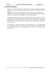
J. Audio Mixer and Mixer Controls
Each 4MP3-MSC has a built-in digital audio mixer capable of audio panning in
realtime. Panning and fading are initiated by script commands. The mixer engine is
configured as
Input1
Parametric EQ
X
Input1 gain
Delay
Matrix Mixer
X
Output
X
Output1 gain
Global Volume
Only channel 1 is show, but all the input and output channels are configured
identically. The MP3 decode 1 outputs are permanently mapped to Input1 and Input2,
decoder 2 to Input3 and Input4, decoder 3 to Input5 and Input6 and decoder 4 to
Input7 and Input8. The external stereo analog inputs are mapped to Input9 and
Input10. The 8 inputs of the first ADAT channel are mapped to Input11 to Input18.
The 8 inputs of the second ADAT channel are mapped to Input19 to Input26. Outputs
1 to 8 are mapped to the 8 analog outputs of the 4MP3-MSC. Outputs 9 to 16 are
mapped to the 8 outputs of the first ADAT channel and outputs 17 to 24 are mapped
to the outputs of the second ADAT channel. However, not all inputs and outputs are
active. The number of active inputs and outputs are determined by the size of the
Matrix Mixer. The default matrix size is 10 x 16. The matrix size can be changed in
the script with the following command
MatrixSize = <number of inputs>,<number of outputs>;
For example,
MatrixSize = 10,18;
// size matrix size to 10 x 18
Whenever the matrix size is changed, the DSP core is reset. That means all the input
and output volumes would be reset to unity (0.0 dB), output delays set to zero, all
parametric EQ banks assigned with 1 Unity filter.
The input and output gains in dB are predefine script variables of type Float. The
input gain variables are iVolume1, iVolume2, to iVolume26 and the output gain
27
variables are oVolume1, oVolume2 to oVolume24. Input gains and global volume
cannot be more than unity, i.e., all iVolumeX and the volume variables must be less
than or equal to zero in dB. However, the output gains can be as high as 12dB, i.e., all
oVolumeX variables must be less than or equal to 12dB. The output delays are
predefined script variables of type Long, oDelay1 to oDelay24. The unit is in
milliseconds. The maximum delay for each output is 225ms. Even though all these
variables are predefined, only a subset defined by the size of the Mixer Matrix is
active.
There are a total of 64 parametric EQ filters available for the entire mixer. They can
be partitioned unevenly amongst the output channels. The minimum number of filter
assigned to each output is 1. That means 1 filter must be assigned to an output even
though that output does not require output equalization. The default number of filters
assigned to each output is 1 and the default filter is a unity filter, i.e., the output of the
filter is the same as the input. Use the NFilter command to partition the filters.
NFilter = 1,2,3,1,3,2;
The above command assigns 1 filter to output 1, 2 to output 2 and 3 to output 3, etc.
The number of entries specified with the NFilter command must not exceed the
number of active outputs. Repartitioning the filters would also initialize all the filters
to unity filters.
Once the fitlers are partitioned, we can set the filter parameters with the Filter
command. There are three different Filter command formats:
Filter(<which output>,<which filter>) = <filter type>,<filter frequency>;
Filter(<which output>,<which filter>) = <filter type>,<filter frequency>,<filter
gain>;
Filter(<which output>,<which filter>) = <filter type>,<filter frequency>,<filter
gain>,<filter bandwidth>;
<which output> specifies the mixer output number. <which filter> specifies which
filter of the given output. <filter type> can be one of the 5 predefined constants
Lowpass, Highpass, Lowshelf, Highshelf and Bandpass. <filter frequency> is an
integer constant between 10 and 20000 and the unit is Hertz. <filter gain> is a
floating point constant between -40.0 to 15.0 in dB. <filter bandwidth> is a floating
point constant between 0.05 to 4.0 in octaves. A Lowpass or Highpass filter must be
specified with the first form. A Lowshelf or Highshelf filter must be specified with the
second form and the Bandpass with the third form. For example,
Filter(1,2) = Lowpass, 15000;
// Lowpass with 3dB frequency at 15kHz.
Filter(2,1) = Highshelf, 3000, 3.0; // Highshelf at 3kHz and gain of 3dB.
Filter(3,1) = Bandpass,1000,-6.0,1.0; // Bandpass at 1kHz, -6dB cut
// and bandwidth of 1 octave.
28
Any filter can be enabled or disabled with the follow commands
Filter(<which output>,<which filter>) = 1; // enable filter
Filter(<which output>,<which filter>) = 0; // disable filter
The cross-point multipliers of the mixer matrix can be changed with the Fade
command. There are four such Fade commands.
Fade to Unity in <fade time expression>;
Fade to Zero in <fade time expression>;
Fade <input number> to <output gain list> in <fade time expression>;
Fade <input number> to <number> of <output gain list> in
<fade time expression>;
The first form fades the diagonal elements of the matrix to unity, i.e. output 1 equals
to input 1, output 2 equals to input 2, etc. All off diagonal cross-points are faded to
zero, i.e., no contribution to the outputs. The second form fades all output to off. The
<fade time expression> is an arithmetic expression evaluated to an integral number of
frames representing the fade duration.
For the last two forms, <input number> must be an integer constant specifying the
input number. <output gain list> is a list of the form
(<output number1>,<gain expression1>),
(<output number2>,<gain expression2>),…,
(<output numberN>,<gain expression>)
where <output numberX> must be an integer constant specifying the output number
and <gain expressionX> is an arithmetic expression evaluated to a floating point
value specifying the cross-point gain in dB. For the last form, <number> is an integer
constant specifying how many entries of the <output gain list> to be picked
randomly. For example,
Fade 2 to (1,-3.0),(2,-64.0) in 90;
would fade input 2 to output 1 to -3.0dB and to output 2 to -64.0dB in 3 seconds. A
cross-point gain of -64.0dB is equivalent to turning off that cross-point.
Fade 2 to 2 of (1,-3.0),(2,-4.0),(3,-5.0),(4,-1.0) in fadeTime;
would fade input 2 to two of the 4 outputs in the list to the corresponding cross-point
gain. The two outputs are picked randomly out of the 4 specified. The fade duration is
stored in the variable fadeTime.
Fade 2 to (5, - random(3,6)) in 300;
29
would fade input 2 to output 5 in 10 seconds. The final cross-point gain is random
between -3 to -6 dB.
Fade 1 to (1,-64.0),(2,0.0) in 90;
Idle for 90;
Fade 1 to (2,-64.0),(3,0.0) in 90;
Idle for 90;
Fade 1 to (3,-64.0),(4,0.0) in 90;
Idle for 90;
would pan input 1 from output 1 to output 2 in 3 seconds, then from output 2 to
output 3 in 3 seoncds, and finally from output 3 to output 4 in 3 seconds.
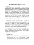
Hardware with version 2.0 and above has 8 analog audio inputs added. However, we
don’t have enough resources to present another 8 inputs to the DSP. So a
multiplexing scheme is created to remap inputs to the DSP. Because stereo ADCs are
used, there are 4 bitstreams each carrying two channels of analog inputs. The
multiplexing scheme is shown in the following figure:
Not Used
One of 4 possibilities
Analog Channel
1&2 Bitstream
MP3 Decoder 1
Bitstream, DSP
inputs 1&2
ADAT1 Channel
1&2 Bitstream,
DSP inputs 11&12
ADAT2 Channel
1&2 Bitstream,
DSP inputs 19&20
Similarly, analog channel 3 & 4 bitstream can replace MP3 decoder 2 bitstream (DSP
inputs 3 & 4), ADAT1 channel 3 & 4 bitstream (DSP inputs 13 & 14) or ADAT2
channel 3 & 4 bitstream (DSP inputs 21 & 22), etc. So we need two binary bits to
represent each analog channel pair. Altogether we need 8 bits to select the 4 analog
channel pairs. The selection is represented by a predefined global variable
AnalogAudioIn. Bits 1 & 2 are for analog channel 1 & 2, bits 3 & 4 for channels 3 &
4, etc. When AnalogAudioIn is 0, no analog input is used. When AnalogAudioIn is
0x55, all the MP3 decoders are replaced with analog audio inputs and the analog
inputs are at DSP inputs 1 to 8. When AnalogAudioIn is 0x5, then DSP inputs 1 to 4
are analog inputs 1 to 4, DSP inputs 5 to 8 are from the outputs of MP3 decoders 3
and 4.
30
K. Flow Control
Showgram has an extensive set of execution flow control commands. The simplest
form is the Jump statement, which informs the cue engine to resume execution of the
script at a statement with the given label. For example,
Jump gotIt;
where gotIt is a statement label. A statement label is a user-defined name starting at
the beginning of a line followed by a colon. For example,
gotIt: cnt++;
// statement with the label gotIt.
The While statement allows execution of a simple or compound statement to be
executed while a logical expression is evaluated to True. The syntax is
while (logical_expression)
simple_or_compound_statement;
For example,
while (sensor && runAllowed)
{
tally = !tally;
idle for 30;
}
// toggle tally
// idle for a second
The above segment will blink the tally light at a rate of one second on followed by
one second off while both sensor and runAllowed are True.
The If statement allows a simple or compound statement to be executed if a logical
condition is evaluated to True. The If-Else combination statement allows an alternate
statement to be executed if the condition is evaluated to False. For examples,
if (sensor && runAllowed)
{
tally = True;
myRelay = False;
}
if (addOne)
count++;
if (dogBarking)
{
prepare dogClip to 1;
clstartw 1;
}
else
// turn on the tally light
// release the relay
// if addOne is true, increment variable count
// prepare MP3 clip 1
// start playing and wait until done
31
{
prepare catClip to 2;
clstart 2;
// prepare MP3 clip 2
// start but don’t wait, just preceed
}
In many occasions, we would like to execute different statements based on different
values of an integer variable. One way to achieve this goal is with multiply nested ifelse statements:
if (cnt == 1)
Statement1;
else if (cnt == 3)
Statement 2;
else if (cnt == 5)
Statement3;
else if (cnt == 7)
Statement4;
else
Statement5;
The switch-case statement is a more elegant and more readable way to achieve the
same goal:
switch (cnt)
{
case 1:
statement1;
break;
case 3:
statement2;
break;
case 5:
statement3;
break;
case 7:
statement4;
break;
default:
Statement5;
Break;
}
The simple break statement terminates the switch-case statement. If a break statement
is not used at the end of a case, the statement in the next case will also be executed
until a break is encountered or the last case has been reached. The break statement
can also be used inside a while statement to break out of the while loop. When no case
32
is matched, the statement in the default section would be executed. If no default
section is defined, no statement would be executed.
The for statement allows execution of a simple or compound statement for a given
number of time. The syntax is
For (initialize_statement; loop_condition; once_per_loop_statement)
simple_or_compound_statement;
where initialize_statement is a simple statement to be executed at the beginning of the
for statement block. loop_condition will be checked at the top of the for loop. If it is
True, simple_or_compound_statement will be executed once. If it is False, the for
loop terminates and the cue engine will move forward to the next statement.
once_per_loop_statement is a simple statement that will be executed once after the
simple_or_compound_statement has been executed. After its execution, the cue
engine will check the loop_condition again and the loop continues. For example,
For (count = 1; count <= 10; count++)
{
serialPort.Format(“count = %ld”); // send “count = n” to the serial port, where
// n is updated with the value of count
idle for 30;
// wait for a second
}
The above segment sends the strings “count = 1”, “count = 2”, …, “count = 10” to the
serial port once a second. You may also use a break statement to get out of the for
loop prematurely.
The In statement (4MP3-MSC Firmware V1.3 and above) allows a simple or
compound statement to be executed over and over in a given period of time. The
syntax is:
In (<integer expression>)
Simple_or_compound_statement;
where <integer expression> will be evaluated to give an integer, specifying the
duration of the execution period. For example,
In (300)
{
if (sensor.down) jump gotIt; // got sensor trigger, do something
}
// no sensor trigger, do something else
will wait for the sensor to be triggered, but no longer than 10 seconds (300 video
frames).
33
The On Halt Jump statement allows cleaning up when a cue is told to halt. For
example,
Cue myCue
{
halt if (!MasterOn);
on halt jump stopIt;
prepare myClip to 1;
clstartw 1;
exit;
stopIt:
clstop 1;
}
// halt if MasterOn is false
// if halted, jump to stopIt
// prepare clip 1
// start playback and wait
// exit the cue, normal exit here
// stop the playback if halted
L. Remote Message Logging
Each 4MP3-MSC unit can send information to a PC host to be logged in a file. The
PC must be running the 4MP3CON application. The 4MP3CON application creates a
different log file for each day of the week and create different log files for different
4MP3-MSC units on the network. To enable logging, the IP address of the PC host
must be specified with the LogHostIP command in the global scope, i.e., output any
Cue. For example,
LogHostIP = 192.168.1.2;
Once the IP is specified, you may send logging information to the PC with the
LogHost command inside any cue.
LogHost = “Movie started”;
LogHost = “Clip description is “ + myClipVar.dsc;
In addition to the log information sent from the script, the 4MP3-MSC itself sends a
lot of other useful information regarding the state of the unit and starting/stopping of
all clips being played. The amount of message can be throttled down by using the
global property Verbose:
Verbose = TRUE;
The Verbose statement must be a global statement, i.e., outsize of any Cue body.
When Verbose if FALSE, starting and stopping of cues won’t generate any log
messages. Verbose is by default FALSE if not specified in the script.
For quick debugging, you can broadcast messages to all computers in the network
running the 4MP3CON application with the DEBUG statement. The message would
show up in the debug window at the bottom of the main 4MP3CON dialog. The
debug message would also be added to the log file.
34
Debug = “Something happened here and now!”;
M.
Keyboard Scanning
4MP3-MSC has built-in keyboard scanning using multiple digital inputs and digital
outputs. On power up or loading of script, keyboard scanning is disabled. Use the
KeyScan command to enable scanning.
KeyScan <nInputs>,<nOutputs>;
where <nInputs> is an integer between 2 and 8 and <nOutputs> is between 2 and 22.
The sumof <nInputs> and <nOutputs> must not be greater than 24. The unit
automatically allocates hardware resources starting with I/O pin1 for keyboard matrix
input 1. The outputs are assigned immediately after the input pins. For example, if the
matrix is 4x4, then I/O pins 1 to 4 are for matrix inputs and I/O pins 5 to 8 are for
matrix outputs.
Once keyboard scanning is enabled, you may map Bit variables to the matrix crosspoint.
Bit myButton1 = ScanNode(1,2);
// switch at input 1 and output 2
N. IR and Pseudo-Serial Transmission
All the digital outputs are capable of sending out IR signals or serial byte streams.
The serial byte streams would follow the RS232 protocol except that the voltage level
would not be strictly RS232. The send out IR signals, an IR file must be included in
the script file. To include an IR file, use the preprocessor director #include
#include “aquos.inc”
The IR file consists of a series of #define statements, one for each IR code. Use the
FIRE command to send an IR code to a digital output:
#include “aquos.inc”
Bit ir = dout2;
// define a digital output bit variable
Cue myCue
{
Fire AQUOS_POWER_ON to ir;
}
where AQUOS_POWER_ON is defined in the aquos.inc file. Although IR can be
fired to all 24 digital outputs, there is only one IR engine in the system. That means
only one IR output would be active at anytime. The sequencing of multiple firings
issued at the same time is handled by the show controller. If multiple emitters must
35
be fired with the same code simultaneously, the emitters must be electrically wired in
parallel.
There are two ways to connect an IR emitter to the digital output. When a single IR
emitter is used, the emitter can be connected between the digital output and lamp
ground. When multiple emitters are connected in parallel, they must be connected
between the digital output and lamp power with an appropriate current limiting
resistor. The IR file must be created correctly for the two different wiring methods.
So if you have multiple Aquos monitors, 3 wired together and 1 wired by itself
between output and ground, two separate IR files must be created even though all the
monitors are of the same type and the code name must be different.
The IR engine can also be used to fire pseudo RS232 serial byte streams to the digital
outputs. “pseudo” in the sense that the voltage level is not strictly RS232 levels. But
it works for most RS232 receivers. The connection is as simple as connecting the
digital output and lamp ground to the remote RS232 RXD and GND wires. Only
literal string constants can be sent out to the digital ports. The syntax is:
Ssend “my string” to myBitVar at myBaudrate;
where “my string” is a literal string, myBitVar is a digital output bit variable and
myBaudrate is an integer constant specifying the baudrate. For example,
Bit pseudoSerial = dout2;
Cue myCue
{
Ssend “hi there” to pseudoSerial at 9600;
}
O. Sending Email
You may send email messages directly from a script. This is useful for sending out
warning or emergency messages to personnel overseeing the system. You must define
all the necessary addresses before you can issue the send command. The sequences
are:
MailTo = “[email protected]”;
MailFrom = “[email protected]”;
MailSubject = “Testing email”;
MailHost = 12.34.56.78;
MailBody = “this is the message”;
MailSend;
// must have, can be string expression
// must have, can be string expression
// optional, can be string expression
// must have and must be numeric IP
// can be string expression
// send it out
MailHost must be defined. It is the SMTP server that will actually send the email to
the outside world. This host must be configured to allow email relaying from the
show controller sending the email. Once you have defined the To and From address
36
and the MailHost address, you may send multiple emails to the same address by
changing MailBody and then execute MailSend. Since string constants cannot be
longer than 255 characters, the mail body would be limited to 255 characters. MailTo,
MailFrom, MailSubject, MailHost and MailBody are write only variables.
P. Showgram Compiler
Showgram script files are plain text files. They can be edited with the built-in editor
of the compiler or any text editors or word processors that are capable of saving files
in plain text format. Names of all Showgram script files must end with an extension
of “.mps”. Each script file must be compiled into a binary form for downloading.
The compiler program 4mp3c.exe is a 32-bit Microsoft Windows program. It has a
built-in text editor very similar to the Windows’ NotePad program. Figure 1 shows a
running session of the compiler.
Figure 1. A running session of the 4MP3-MSC compiler.
The last button on the toolbar is the compile button. Or you may pull down the File
menu to access the compile function. Once compiled, a warning and error screen will
popup to show you the compilation result. If an error occurred, simply clicking the
error line will send the cursor in the editor window to the offending line.
If myscript.ps is the input file, the compiler generates the following output files
37
myscript.ppf
myscript.bin
myscript.lst
myscript.map
- file generated by the pre-processor.
- download binary file.
- listing file generated only when the “-l” option is specified.
- map file generated only when the “-m” option is specified.
The pre-processor of the compiler looks for lines starting with “#define” and performs
the corresponding macro substitutions. The pre-processed file is then compiled. The
format of the “#define” macro is
#define macroName macroBody
where “macroName” is a string which is going to be substituted with the
“macroBody”. For examples,
#define maxFrequency 12345
#define myName
“George W. Gore”
The pre-processor will look throughout the script file for the string “maxFrequency”
and replaces it with the string “12345”. Similarly, “myName” will be substituted with
“G.W. Gore”. Pre-processor “#define” macros are very useful for maintaining global
parameters that can be adjusted at only one location inside the script file, instead of
searching the file to perform multiple substitutions. Sometimes it is easier to look in
the pre-processed file for errors embedded in the pre-processor macros. Pre-processor
macros are cannot be recursive, i.e. you may not refer to a pre-processor macro inside
the definition of another pre-processor macro.
Q. Command Reference
1. Cue Commands
a. Absolute;
Force the cue clock to be the same as the system clock.
b. AutoStart;
Cue with this command included in its body starts automatically when the
4MP3-MSC is powered up, immediately after a new script has been
downloaded, or when the system is scheduled to start up.
c. CStart cueName;
CStart cueName1,cueName2,…,cueNameN;
The first form starts the cue with the name cueName. However, do not wait
for cueName to finish. cueName can be a literal cue name or a variable of type
CueVar. The second form starts the list of cues. cueNameX can be a literal
cue name or a variable of type CueVar.
38
d. CStartw cueName;
CStartw cueName1,cueName2,…,cueNameN;
The first form starts the cue with the name cueName and wait till it has
finished. cueName can be a literal cue name or a variable of type CueVar. The
second form starts the list of cues and waits till all the cues stopped.
cueNameX can be a literal cue name or a variable of type CueVar.
e. CStop cueName;
CStop cueName1,cueName2,…,cueNameN;
The first form stops the cue with the name cueName. cueName can be a literal
cue name or a variable of type CueVar. The second form stops all the cues in
the list. cueNameX can be a literal cue name or a variable of type CueVar.
f. CWait cueName;
CWait cueName1,cueName2,…,cueNameN;
The first form waits for the cue cueName to stop. cueName can be a literal cue
name or a variable of type CueVar. The second form waits for all the cues in
the list stopped. cueNameX can be a literal cue name or a variable of type
CueVar.
g. Enable If <logical expression>;
The cue engine evaluates the logical expression <logical expression>
periodically. If the result is True and if the cue is not halted, not inhibited and
not being held off, the cue will then start running. For example
Cue myCue
{
Enable if (systemOn && button.Down);
// other command statements
}
h. Halt If < logical expression>;
If the cue is running, the cue engine evaluates the logical expression <logical
expression> periodically. The cue will be halted if the result is True. For
example,
Cue myCue
{
Halt if (!systemOn || docentOn);
// other command statements
}
i. HoldOff = <duration>;
The parameter <duration> must be an integer constant in number of video
frames (30 frames/sec). Once the cue has started execution, it would be
prevented to start again for the subsequent <duration> frames. For example,
39
Cue myCue
{
HoldOff 0:5:0.0;
// holdoff 5 minutes
// other command statements
}
j. Inhibit If <logical expression>;
If the cue is not running, the cue engine evaluates the logical expression
<logical expression> periodically. The cue will be prevented from starting as
long as the result is True. For example,
Cue myCue
{
Inhibit if (dogBarking);
// other command statements
}
k. On Halt Jump jumpLabel;
If the cue is halted either by the Halt If expression, the CStop command or
scheduled system stop, jump to the statement with label “jumpLabel”. For
example,
Cue myCue
{
On Halt Jump cleanup;
// other statements
exit;
// normal exit
cleanup:
// do some cleanup here
}
l. Relative;
Set the cue clock to relative mode. In such mode, the cue clock will be reset to
mid-night (zero) when the cue starts. All time references inside the cue will be
relative to this cue start time. By default all cues are in relative mode unless
the Absolute command is specified inside the cue body. For example,
Cue myCue
{
Relative;
// some statements
@0:0:1.0
nop;
// more statements
}
// execute this 1 second after cue started
40
m. Schedule = TRUE; or Schedule = FALSE;
When the 7-day system-wise scheduling system is turned on, this command
tells the cue engine that this cue is to follow the global schedule when
Schedule is set to TRUE, or not when set to FALSE.
n. StartTime = op_hour_start;
o. StopTime = op_hour_stop;
op_hour_start and op_hour_stop are integer constants or SMPTE times. If
op_hour_stop is larger than op_hour_start, the cue is allowed to run only if the
system clock is between op_hour_start and op_hour_stop. If op_hour_stop is
less than op_hour_start, the cue is allowed to run from mid-night to
op_hour_stop and then from op_hour_start to mid-night. For example
Cue myCue
{
StartTime = 7:0:0.0;
StopTime = 17:0:0.0;
// more statements
}
// allow to run from 7 am
// to 5 pm
2. Time Related Commands
a. Elapsed(); or Elapsed(<integer expression>);
The first form returns the time elapsed since the cue started in number of
video frames (30 frames/sec). The second form returns the time elapsed since
the time specified by the value of the integer expression <integer expression>.
For examples
lastTime = Now;
// some statements here
myInt = Elapsed(lastTime);
// set lastTime to current time
// time spent executing those statements
b. FrameSync;
Wait idly until the system clock advances to the next video frame (30
frames/sec).
c. Idle For <integer expression>;
Wait idly for a duration equal to the result of the integer expression <integer
expression>, in video frames (30 frames/sec).
d. Idle for nextDay;
Wait idly until just past midnight. This is useful when we are scheduling
events to be run periodically and daily. Consider the following example:
Cue dailySchedule
41
{
absolute;
Loop:
*08:00:00.00 cstart ShowVideo;
*12:00:00.00 cstart ShowVideo;
*16:00:00.00 cstart ShowVideo;
jump loop;
}
// use system clock
// start show at 8am
// start show at 12pm
// start show at 4pm
// do it again next day
After starting the show at 4pm, the loop will be run continuously until
midnight without starting the show again. After midnight, it would sit idly
waiting for 8am. To prevent this continuous looping, we modify the cue to
Cue dailySchedule
{
absolute;
Loop:
*08:00:00.00 cstart ShowVideo;
*12:00:00.00 cstart ShowVideo;
*16:00:00.00 cstart ShowVideo;
idle for nextDay;
jump loop;
}
// use system clock
// start show at 8am
// start show at 12pm
// start show at 4pm
// wait till just beyond midnight
// do it again next day
After starting the show at 4pm, we would sit idly till just beyond midnight and
then we loop back to the beginning and wait for 8am.
3. Loop/Flow Control Commands
a. Break;
Jump out of the current compound statement, except if the current compound
statement is the main body of a cue. For examples,
while (doMore)
{
if (getOut) break;
}
// if getOut is true, break out of while
b. Continue;
Jump back to the beginning of the compound statement associated with a
While, For or In loop. For example,
While (tmp > 0)
{
if (tmp == 5) continue;
// back to beginning of loop
42
// gets here if tmp is not equal to 5
// more statements here
}
c. Exit;
Exit and stop a cue without running any On Halt statements. For example,
Cue myCue
{
on halt jump recover;
// some statements here
exit;
recover:
// do halt recovery here
}
d. For Loop
The syntax of a For loop is
// exit the cue here
For (initialization_statement; loop_condition; pre_loopback_statement)
Simple_or_compound_statement;
On entry of the For loop, the initialize_statement will be executed once. The
loop_condition logical expression is then evaluated. If the condition is true,
the
Simple_or_compound_statement
will
be
executed.
The
pre_loopback_statement is then executed before jumping back to check the
loop_condition again. For example,
For (cnt = 0; cnt < 10; cnt++)
{
tallyLight = True;
idle for 30;
tallyLight = False;
idle for 30;
}
On entry of the above For statement, the variable cnt will be initialized to 0.
cnt is then compared with 10. If cnt is less than 10, execute the 4 statements
inside the pair of curly braces. cnt is then incremented. cnt is then compared
with 10 again and the loop repeated until cnt is equal to 10.
e. If and Else
There are several forms of If and else statement. The simplest form is
If (logical_expression)
Simple_or_compound_statement;
43
If
the
logical
expression
is
evaluated
to
True,
Simple_or_compound_statement will be executed. For example,
the
If (masterOn && button.down)
tmp = tmp + 1;
The next form is
If (logical_expression)
Simple_or_compound_statement;
else
another_simple_or_compound_statement;
In this case, the another_simple_or_compound_statement will be executed
instead if the logical_expression is False.
The final form is a multiple nesting of the If-else statement
If (logical_expression1)
Simple_or_compound_statement1;
else if (logical_expression2)
Simple_or_compound_statement2;
else if (logical_expression3)
Simple_or_compound_statement3;
….
f. In
The syntax of the In statement is
In (<integer expression>)
Simple_or_compound_statement;
On entry of the In statement, the integer expression is evaluated. The
Simple_or_compound_statement is then executed repeatedly for a number of
video frames (30 frames /sec) equal to the value of the integer expression. For
example,
In (300)
{
tmp++;
if (button.down) break; // if we get a button push, exit this loop
// otherwise, this loop will be run for 10 seconds
}
44
g. Jump/Goto Label;
Do an unconditional jump to the given label. For example,
h. Switch, Case and Default
The syntax is
Switch (<integer expression>)
{
case integer_value1:
simple_or_compound_statement1;
break;
case integer_value2:
simple_or_compound_statement2;
break;
// more cases here
case integer_valueN:
simple_or_compound_statementN;
break;
default:
simple_or_compound_default_statement;
}
On entry, the <integer expression> is evaluated. The result is then compared
with integer_value1, integer_value2, …, integer_valueN. If the result is equal
to integer_valueK, say, then simple_or_compound_statementK will be
executed. If it does not match any of the case integers,
simple_or_compound_default_statement will be executed. If no default case is
specified, the cue engine will proceed to the next statement. If a break
statement is not included at the end of the case statement, then the next case
statement will also be executed. For example,
Switch (tmp*2+1)
{
case 1:
result = 1;
break;
case 5:
result = 5;
case 9:
result = 9;
break;
default:
result = 11;
}
45
If tmp has a value of 0, then result will be 1. If tmp has a value of 2, the result
will not be 5, but 9 since the break statement is missing after the line “result =
5;”. If tmp is not 0, 2 nor 4, then the result will be 11.
i. While
The syntax is
While (logical_condition)
Simple_or_compound_statement;
The Simple_or_compound_statement will be executed repeatedly while the
logical_condition is True. For example,
While (!button.Down)
{
// do something here
tmp++;
}
4. String/Serial Port/Pioneer Player Commands
a. AtoI(<string expression>)
Scan the result of the string expression until it encounters the first non-digit
chararacter and return the corresponding integer value of the string. For
example,
myInt = AtoI(“124abc”);
myInt = AtoI(“abc124”);
digit
// myInt will be set to 124
// myInt will be zero since the first character is not a
b. AtoF(<string expression>)
Scan the result of the string expression until it encounters the first character
not being one of “0123456789,+-eE” and return the corresponding floatingpoint value of the string. For example,
myFlt = AtoF(“124abc”);
// myFlt will be set to 124.0
myFlt = AtoF(“-3.456apples”); // myFlt will be set to –3.456
c. .Baud
This is a write-only member property of a serial-port-mapped string variable.
It assigns an integer value to set the baud rate of the corresponding serial port.
The supported baud rates are 300, 600, 1200, 2400, 4800, 9600, 19200,
38400, 57600 and 115200. The default rate is 9600 for port 1 and 2, and
115200 port3 (the host port). Changing the baud rate also causes the serial
46
port hardware to be reinitialized and the transmit and receive buffers emptied.
For example,
String pc = port1;
pc.baud = 9600;
// set port 1 serial baud rate to 9600
d. .Block
This is a read-only member property of a serial-port-mapped string variable
with the serial port connected to a Pioneer laser disc player. It returns the
current block number of the player. For example,
String discPlayer = port1;
If (discPlayer.Block != 1)
{
// do something
}
e. .Chapter
This is a read-only member property of a serial-port-mapped string variable
with the serial port connected to a Pioneer DVD player. It returns the current
chapter being played or after seeking. For example,
String discPlayer = port1;
If (discPlayer.Chapter != 2)
{
vsearchw discPlayer to “CH2”;
}
// search to Chapter 2
f. .CSize
This is a write-only member property of a serial-port-mapped string variable.
It is used to specify the number of bits in each transmitted character. The
supported values are 5, 6, 7 and 8 for port 1 and 2, and 8 only for port 3. The
default is 8. For example,
String discPlayer = port1;
DiscPlayer.CSize = 8;
g. .Empy() or .Empty(<integer expression>)
This is a member function of a serial-port-mapped string variable. The first
form without an argument empties the entire serial port receive buffer. The
second form removes a number of characters equal to the result of <integer
expression>. For example,
String discPlayer = port1;
discPlayer.Empty(5);
// empty 5 characters from port
47
h. .Frame
This is a read-only member property of a serial-port-mapped string variable
with the serial port connected to a Pioneer laser disc or DVD player. It returns
the current video frame location being played or after seeking. For example,
String discPlayer = port1;
If (discPlayer.Frame != 1000)
{
vsearchw discPlayer to “FR1000”;
}
// search to frame 1000
i. .Find(string_expression)
This is a member function of a String variable. It evaluates the
string_expression and searches the String variable for the resulting string. If
the string cannot be found, it returns 0. If it is found, it returns the starting
index where the string is. For example,
myStr = “abcdefg”;
myInt = myStr.Find(“ijk”);
myInt = myStr.Find(“cde”);
// not found, myInt will be zero
// found at position 3, myInt will be 3
j. Fmt(fmt_string, variable)
The format function behaves like sprintf in C. It uses the format string
fmt_string and the variable to form a string. It differs from sprintf is that it
only allows one variable at a time. However, the full sprintf capabilities can
be achieved with concatenation of multiple Fmt function calls. For details
about the available format options, please consult a C language reference. For
example,
myInt = 123;
myStr = fmt(“Result = %ld bytes”, myInt); // myStr = “Result = 123 bytes”
The long integer format string %ld is used here since all integer variables in
Showgram are treated as long integer variable in the 4MP3-MSC firmware.
k. .Format(fmt_string, variable)
This is the same as the Fmt function except that it is in a member function of a
String variable. The result of the format function will be stored in the String
variable. So an alternate form of the last example statement is
myStr.Format(“Result = %ld bytes”, myInt);
l. Hold(port_string_variable1,…, port_string_variableN);
Put on hold the transmission of the serial ports corresponding to the list of
serial-port-mapped string variables. For example,
48
String p1 = port1;
String p2 = port2;
Hold(p1, p2);
// put port1 and port2 transmission on hold
m. .Len
This is a member property of a String variable. It returns the number of
characters stored in the parent string. For example,
myStr = “abcde”;
myInt = myStr.len;
// myInt would be 5
n. .Parity
This is a write-only member property of a serial-port-mapped string variable.
It is used to specify the port parity. The supported values are None, Odd, even,
Mark and Space for port 1 and 2, but None only for port3. The default is
None. For example,
String p1 = port1;
P1.parity = Odd;
o. Release(port_string_variable1,…, port_string_variableN);
Release and allow transmission of the serial ports corresponding to the list of
serial-port-mapped string variables. For example,
String p1 = port1;
String p2 = port2;
Release(p1, p2);
// put port1 and port2 transmission on hold
p. .Reset()
This is a member function of a serial-port-mapped String variable. It resets the
serial corresponding serial port: resetting the serial hardware and emptying
both the receive and transmit buffers. For example,
String p1 = port1;
p1.Reset();
q. .SetMSB
This is a member property of a serial-port-mapped String variable. When set
to TRUE, all bytes sent out of the serial port would have the most significant
bit set to 1.
r. .Stopbit
This is a write-only member property of a serial-port-mapped string variable.
It is used to specify the number of stop bit to be included in each transmitted
character. The supported values are 1 and 2 for port 1 and 2, and 1 only for
port 3. The default is 1. For example,
49
String p1 = port1;
p1.Stopbit = 1;
s. .SubStr(start_<integer expression>, stop_<integer expression>)
This is a member function of a String variable. It extracts a sub-string out of
the String variable. The first argument is evaluated to give the starting index
of the sub-string and the second argument gives the ending index. For
example,
String tstr;
String p1 = “abcdef”;
tstr = p1.SubStr(2,5);
// tstr set to “bcdef”
t. .Terminator
This write-only member property of a serial-port-mapped String variable sets
the termination character of the corresponding serial port. String length
calculations and string references are all based on having the termination
character as the last character of a string/sentence. For example,
String p1 = port1;
p1.Terminator = ‘.’;
// set the termination character to ‘.’.
u. .Time
This is a read-only member property of a serial-port-mapped string variable
with the serial port connected to a Pioneer laser disc or DVD player. It returns
the track time of the current play location during a playback or after seeking.
For example,
String discPlayer = port1;
If (discPlayer.time != 1234)
{
vsearchw discPlayer to “TM1234”; // search to time 12:34
}
v. .Track
This is a read-only member property of a serial-port-mapped string variable
with the serial port connected to a Pioneer laser disc player. It returns the
current track being played or after seeking. For example,
String discPlayer = port1;
If (discPlayer.Track != 2)
{
vsearchw discPlayer to “TR2”;
}
// search to Chapter 2
50
w. .Type
This write-only member property of a serial-port-mapped String variable sets
the serial port type. The currently supported types are ASCII and LD. The
ASCII type is for generic message passing via the serial port. On the other
hand, ports with type LD can be controlled with the dedicated video player
functions. For example,
String discPlayer = port1;
discPlayer.type = LD;
x. VPause port_string_variable; or Vpausew port_string_variable;
port_string_variable is a serial-port-mapped String variable with the serial
port connected to a Pioneer laser disc or DVD player. If the player is playing,
this command pauses the player and also blank the video output. The
VPausew form would not return control to the cue engine until the player has
acknowledged reception of the command. For example,
String discPlayer = port1;
discPlayer.type = LD;
// spin up the player and start the play etc here
VPause discPlayer;
y. .VPause and .VPausew
.VPause and .VPausew are member function of a serial-port-mapped String
variable with the serial port connected to a Pioneer laser disc or DVD player.
If the player is playing, this command pauses the player and also blank the
video output. The .VPausew form would not return control to the cue engine
until the player has acknowledged reception of the command. For example,
String discPlayer = port1;
discPlayer.type = LD;
// spin up the player and start the play etc here
discPlayer.VPausew();
z. Vplay port_string_variable; or Vplayw port_string_variable;
port_string_variable is a serial-port-mapped String variable with the serial
port connected to a Pioneer laser disc or DVD player. This command starts the
playback. The VPlayw form would not return control to the cue engine until
the player has acknowledged reception of the command. For example,
String discPlayer = port1;
discPlayer.type = LD;
// spin up the player here
VPlayw discPlayer;
51
aa. .Vplay and .Vplayw
.VPlay and .VPlayw are member function of a serial-port-mapped String
variable with the serial port connected to a Pioneer laser disc or DVD player.
This command starts the playback. The .VPlayw form would not return
control to the cue engine until the player has acknowledged reception of the
command. For example,
String discPlayer = port1;
discPlayer.type = LD;
// spin up the player here
discPlayer.VPlayw();
bb. VSearch and VSearchw
There are two variations of each of these commands. The four forms are
VSearch port_string_variable to <integer expression>
VSearch port_string_variable to string_expression
VSearchw port_string_variable to <integer expression>
VSearchw port_string variable to string_expression
Port_string_variable is a serial-port-mapped String variable with the serial
port connected to a Pioneer laser disc or DVD player. This commands inform
the player to advance its play head to the specified location. The <integer
expression> is evaluated to give a destination assuming the currently active
search mode (frame, track, index, chapter, block etc). The string_expression is
evaluated to give a destination with optional search mode included in the
string. The VSearchw form would not return control to the cue engine until
the player has acknowledged reception of the command. This usually also
means waiting till the search is over. For example,
String discPlayer = port1;
discPlayer.type = LD;
// spin up the player here
VSearchw discPlayer to 1234;
// using default search mode
VSearchw discPlayer to “FR1234” // search to frame 1234
VSearchw discPlayer to “TM1234” // search to time location 12:34
cc. .VSearch and .VSearchw
There are two variables of each of these two member functions of a serialport-mapped String variable. The four forms are
port_string_variable.VSearch(<integer expression>);
port_string_variable.VSearch(string_expression);
52
port_string_variable.VSearchw(<integer expression>);
port_string_variable.VSearchw(string_expression);
This commands inform the player to advance its play head to the specified
location. The <integer expression> is evaluated to give a destination assuming
the currently active search mode (frame, track, index, chapter, block etc). The
string_expression is evaluated to give a destination with optional search mode
included in the string. The .VSearchw form would not return control to the
cue engine until the player has acknowledged reception of the command. This
usually also means waiting till the search is over. For example,
String discPlayer = port1;
discPlayer.type = LD;
// spin up the player here
discPlayer.VSearchw(1234);
// using default search mode
discPlayer.VSearchw(“FR1234”); // search to frame 1234
discPlayer.VSearchw( “TM1234”); // search to time location 12:34
dd. VSend cmdString To port_string_variable; or VSendw cmdString To
port_string_variable;
port_string_variable is a serial-port-mapped String variable with the serial
port connected to a Pioneer laser disc or DVD player. You may send a generic
string ‘cmdString’ to the Pioneer laser disc or DVD player with this
command. This is useful when you need to control the player with player
specific commands that are not provided by other video relayed Showgram
commands. You don’t need to include the command termination character
<CR>. The VSendw form would not return control to the cue engine until the
player has acknowledged reception of the command. For example,
String discPlayer = port1;
discPlayer.type = LD;
// set the stop marker to 1234 and then play
VSend “1234SM PL” To discPlayer;
ee. .VSend or .VSendw
.VSend is a member function of a serial-port-mapped String variable. You
may send a generic string to the Pioneer laser disc or DVD player with this
member function. This is useful when you need to control the player with
player specific commands that are not provided by other video relayed
Showgram commands. You don’t need to include the command termination
character <CR>. The .VSendw form would not return control to the cue engine
until the player has acknowledged reception of the command. For example,
String discPlayer = port1;
discPlayer.type = LD;
53
// set the stop marker to 1234 and then play
discPlayer.VSend(“1234SM PL”);
ff. VStill port_string_variable; or VStillw port_string_variable;
port_string_variable is a serial-port-mapped String variable with the serial
port connected to a Pioneer laser disc or DVD player. If the player is playing,
this command pauses the player but leaves the last video frame on the video
output. The VStillw form would not return control to the cue engine until the
player has acknowledged reception of the command. For example,
String discPlayer = port1;
discPlayer.type = LD;
// spin up the player and start the play etc here
VStillw discPlayer;
gg. .VStill and .Vstillw
.VStill and .VStillw are member function of a serial-port-mapped String
variable with the serial port connected to a Pioneer laser disc or DVD player.
If the player is playing, this command pauses the player and also blank the
video output. The .VStillw form would not return control to the cue engine
until the player has acknowledged reception of the command. For example,
String discPlayer = port1;
discPlayer.type = LD;
// spin up the player and start the play etc here
discPlayer.VStill();
hh. VStop port_string_variable; or VStopw por_string_variable;
port_string_variable is a serial-port-mapped String variable with the serial
port connected to a Pioneer laser disc or DVD player. This command stops
and spins down the player. The VStopw form would not return control to the
cue engine until the player has acknowledged reception of the command. For
example,
String discPlayer = port1;
discPlayer.type = LD;
// spin up the player and start the play etc here
VStopw discPlayer;
ii. .VStop and .VStopw
.VStop and .VStopw are member function of a serial-port-mapped String
variable with the serial port connected to a Pioneer laser disc or DVD player.
This command stops and spins down the player. The .VStopw form would not
return control to the cue engine until the player has acknowledged reception of
the command. For example,
54
String discPlayer = port1;
discPlayer.type = LD;
// spin up the player and start the play etc here
discPlayer.VStopw();
5. MP3 Playback Commands
a. ClStart <comma separated decoder list>
ClStartw <comma separated decoder list>
Start the playback of a previously prepared MP3 clips. The ClStartw form
starts the playback and waits till the playback is over. The <comma separated
decoder list> is one or more decoder number separated by commas. For
example,
ClStartw1,3;
// start decoders 1 & 3 and wait till both
// both decoders have finished.
b. ClStop <comma separated decoder list>;
Force an immediate stop of the MP3 playback. For example,
ClStop1,3;
// stop decoders 1 & 3
c. ClWait <comma separated decoder list>;
Wait idly until the MP3 playback is over. For example,
ClWait 1,3;
// wait till decoder 1 & 3 finished
d. ClResume <comma separated decoder list>;
Resume playback at the specified decoders. For example,
ClResume 1,3;
// resume playback at decoder 1 & 3
e. ClPause <comma separated decoder list>;
Pause the specified decoders. For example,
ClPause 1,3;
// pause decoder 1 & 3
f. Prepare
Prepare a MP3 clip for playback. There are 2 forms of this command:
Prepare <clip name or clip var> to <decoder number>;
Prepare repeat <clip name or clip var> to <decoder number>;
55
<clip name or clip var> is either a literal clip name defined earlier or a
variable of type ClipVar. The second form will prepare the clip to be
played repeatedly.
Prepare myClip to 2;
// prepare clip myClip to play at decoder 2
Prepare repeat myClipVar to 2; // prepare clip assigned to the myClipVar
// ClipVar variable to be played at decoder 2
// and loop repeatedly.
6. Digital Mixer Related Commands
a. MatrixSize <nInputs>,<nOutputs>;
Sets the size of the mixer matrix. <nInputs> must be between 8 and 18 and
<nOutputs> must be between 8 and 24. When this command is issued, the
DSP core is reinitialized. That means the filter banks need to be repartitioned,
filter parameters, input volumes, output volumes and output delays need to be
set again. For example,
MatrixSize 10,16;
// 10 inputs and 16 outputs
b. NFilter
<nFilter1>,<nFilter2>,…,<nFilterN>;
Distribute the 64 available parametric EQ filters amongst the output filter
banks. The parameter list must not be longer than number of outputs defined
for the mixer matrix. If the number of parameters is less than the number of
outputs defined for the mixer matrix, then the unspecified outputs are set to
have 1 unity filter in their filter bank. The sum of parameter list also should
not exceed 64. After repartitioning, all the filters would be initialized to unity
filters. For example,
NFilter 2,3,2,2,2;
c. Filter(<which output>,<which filter>) = 1;
Fitler(<which output>,<which filter>) = 0;
The first form enable filter <which filter> of output <which output>. For
example,
Filter(2,2) = 0;
// disable filter 2 or output 2
d. Filter(<which output>,<which filter>) = Highpass,<filter frequency>;
Filter(<which output>,<which filter>) = Lowpass,<filter frequency>;
The first form defines a highpass filter at the specified filter frequency and the
second form defines a lowpass filter. <filter frequency> must be an integer
between 20 and 20000Hz. For example,
Filter(1,2) = Lowpass,4000;
// lowpass at 4kHz.
56
e. Filter(<which output>,<which filter>) = Highshelf,<filter frequency>,<filter
gain>;
Filter(<which output>,<which filter>) = Lowshelf,<filter frequency>,<filter
gain>;
The first form defines a high shelf filter at the specified frequency and the
specified gain. <filter frequency> must be an integer between 20 and
20000Hz. <fitler gain> must be between -40.0 and 15.0 in dB. For example,
Filter(1,2) = Highshelf,4000,3.0;
// highshelf at 4kHz with 3dB gain
f. Filter(<which output>,<which filter>) = Bandpass,<filter frequency>,<filter
gain>,<filter bandwidth>;
Defines a bandpass filter. <filter frequency> must be an integer between 20
and 20000Hz. <filter gain> must be between -40.0 and 15.0 dB. <filter
bandwidth> must be between 0.05 and 4.0 in octaves. For example,
Filter(1,2) = Bandpass,1000,-6.0,1.2;
// bandpass at 1kHz,
// -6dB gain and
// 1.2 octave wide.
g. Fade to Unity in <fade time expression>;
Fade the mixer matrix to a unity matrix in the given fade time. <fade time
expression> is an arithmetic expression to be evaluated to an integral number
of frames assuming 30 frames per second. For examples,
Fade to Unity in 30;
// fade to unity matrix in 1 second
Fade to Unity in (30 + random(60,120));
// fade to unity matrix
// fade time is between 3 to 5 seconds
h. Fade to Zero in <fade time expression>;
Fade all mixer matrix to a zero matrix, i.e. all off, in the given fade time.
<fade time expression> is an arithmetic expression to be evaluated to an
integral number of frames assuming 30 frames per second. For example,
Fade to Zero in 90;
// everything off in 3 seconds
i. Fade <input number> to <output gain list> in <fade time expression>;
Fade the given input to the list of outputs at the given gain. <output gain list>
is one or more of (<output number>,<gain expression>) separated by commas.
<output number> specifies the output and <gain expression> is an arithmetic
expression to be evaluated to a floating point number representing the crosspoint gain in dB. The cross-point gain must be less than or equal to zero dB.
<fade time expression> is an arithmetic expression to be evaluated to an
integral number of frames assuming 30 frames per second. For example,
Fade 2 to (1,0.0),(2,-64.0) in 90;
// fade input 2 to output 1 full
57
// and input 2 to output 2 off
// in 3 seconds
j. Fade <input number> to <number> of <output gain list> in <fade time
expression>
Fade the given input to some of the list of outputs at the given gain. <number>
is the number of outputs to be picked randomly from the list. <output gain
list> is one or more of (<output number>,<gain expression>) separated by
commas. <output number> specifies the output and <gain expression> is an
arithmetic expression to be evaluated to a floating point number representing
the cross-point gain in dB. The cross-point gain must be less than or equal to
zero dB. <fade time expression> is an arithmetic expression to be evaluated to
an integral number of frames assuming 30 frames per second. For example,
Fade 2 to 1 of (1,0.0),(2,0.0) in 90;
// fade input 2 to either output 1
// or output 2 in 3 seconds. The
// chance of picking one or the other
// is 50-50.
7. Digital I/O Related Commands
a. .Count
This is a member property of Bit variables mapped to Din1, Din3, Din5, Din7,
Din9 and Din11. In addition to the standard logical True/False (logical
high/low), there are six digital counters, attached to Din1, Din3, Din5, Din7,
Din9 and Din11. These counters are incremented everytime there is a low to
high transition at the input. The .Count member property returns an integer
value corresponding to the current counter value. Everytime this member
property is referenced, the hardware reset the counter to 0. There are two
counter modes, Linear and Quadrature. Linear counting only involves one
digital input, Din1, Din3, Din5, Din7, Din9 and Din11. Quadrature counting
involves two digital inputs, Din1 and Din2 for one counter and Din3 and
Din4 for counter 2, etc. However, the counter values are still accessed via
Din1 and Din3. For example,
Bit in1 = Din1;
Bit in3 = Din3;
in1.type = Linear;
in2.type = Quadrature;
myInt1 = in1.Count;
myInt2 = in2.Count;
// set it to linear mode
// set it to quadrature mode
// get linear counter value
// get quadrature counter value
b. .DutyCycle
This is a member property of a Bit variable mapped to a digital output
configured to generate a PWM (Pulse Width Modulated) signal. This member
58
property specifies the percentage of the period that the output will be in a
logical high state. For example,
Bit out2 = Dout2;
out2.Type = PWM;
out2.DutyCycle = 50;
// set to 50% duty cycle
c. .io
This is a member property of a Bit variable mapped to a digital output. When
declared TRUE, the given digital output can also be used as a digital input
simultaneously. The output driver will be turned off momentarily periodically
so that the input state of the pin can be sampled. This option is turned off by
default.
d. .Type
This is a member property of a Bit variable mapped to a digital input or
output. This member property does nothing for Din2, Din4 toDin14. For Din1
and Din3, please refer to the .Count member property in above. All 4MP3MSC digital outputs can be configured to generate PWM (Pulse Width
Modulation) outputs. The PWM base frequency is set by the predefined
system variable PWMFreq. The duty cycle is set by the .DutyCycle member
property in above. The two allowable modes are Normal and PWM. By
default, all digital outputs are in Normal mode. For example,
Bit out2 = Dout2;
out2.type = PWM;
// map a Bit variable to Dout2
// change to PWM mode;
8. LCD Display Commands
The LCD display is an optional hardware for the 4MP3-MSC controller. The
display has 2 lines of 20 characters each.
a. .Display
This is a member function of all Bit, Int, Float and String variables. There are
two forms
.Display(line_<integer expression>);
.Display(line_<integer expression>, column_<integer expression>);
The line_<integer expression> is evaluated to give which line of the display to
be used. The column_<integer expression> is evaluated to give the starting
column within the selected line. The value of line_<integer expression> must
be 1 or 2. The value of column_<integer expression> must be between 1 and
20. For Bit, Integer and Float variables, the 4MP3-MSC uses its own default
to format the output. If you want specific output format, please use the
.Format member function or the Fmt function. For examples,
59
myInt.Display(1);
myInt.Display(2, 10);
// display to line 1
// display to line 2 starting at column 10
b. Display
This is an alternate form of the .Display member function. The possible forms
are
Display variable to line_<integer expression>;
Display variable to line_<integer expression> at column_<integer expression>;
For examples,
Display myInt to line1;
// line1 and line2 are predefined constant
Display myFloat to line2 at 10; // display to line 2 starting at column 10
9. Miscellaneous Commands
a. Version = <version number>;
You may define a version number for the script file with the Version
command. It must be defined in the global scope, i.e., not inside any cue.
<version number> can be any integer or floating point constants. For example,
Version = 3.4;
// script version 3.4.
b. hwVersion = <version number>;
You must specify the hardware version to match hardware being used. Some
script capabilities were added as the hardware evolved. Hardware with older
version won’t be able to execute these commands. By knowing the hwVersion,
the compiler would warn you if you try to use features that are incompatible
with the hardware.
c. Verbose = TRUE or Verbose = FALSE
Like Version, Verbose is set to TRUE or FALSE in the compiled script and
cannot be changed in real time with cue statements. By default Verbose is
FALSE. If Verbose is false, the controller won’t generate log messages when a
cue starts or stops.
d. Nop
This command does nothing. It is usually used as a placeholder for timestamping or labeling. For example
@0:1:0.0
loop:
Nop;
Nop;
60
e. DMX = “<DMX command>”;
Send the DMX command to the DMX fade engine. See the DMX section for
the command syntax. For example,
DMX = “C1-10@40F90”;
// channel 1 to 10 to 40% in 3 seconds
f. DMX@<IP Address> = “<DMX command>”;
Send a DMX command to the DMX fade engine of the 4MP3-MSC with the
given IP address. For example,
[email protected] = “C1-10@40F90”;
g. UDP@<IP Address>,<UDP Port> = “<UDP packet>”;
Send a UDP packet to the given UDP port of the machine with the given IP
address. This is a generic UDP packet and so the recipient does not need to be
a 4MP3-MSC. For example,
[email protected],10002 = “C1-10@40F90”;
Sends the DMX command to port 10002 of the machine with IP address
192.168.1.2.
h. LogHostIP = <IP Address>;
Tell the 4MP3-MSC unit that all logging information should be sent to the
machine with the given IP address. For example,
LogHostIP = 192.168.1.2;
i. LogHost = “<Message to be logged>”;
Send the log message to the log host. For example,
LogHost = “Show started”;
j. Mathematical functions - Sin(x), ASin(x), Cos(x), ACos(x), Tan(x), ATan(x),
Sqrt(x), Exp(x), Log(x), Log10(x), Pow10(x)
All these functions take a Float argument and return a Float value.
k. Random(max_<integer expression>); or Random(min_<integer expression>,
max_<integer expression>);
This functions return a random integer value. min_<integer expression> will
be evaluated to give the lower bound of the range of values the random
number will fall within. max_<integer expression> gives the upper bound of
the range. The first form with a single argument assumes that the lower bound
is always 1. For example,
myInt = Random(100);
// random number between 1 and 100
61
myInt = Random(50,100);
// random number between 50 and 100
R. Predefined System Variables and Constants
1. Adc1, Adc2, Adc3, Adc4 – analog input at the analog DB9
These are readonly Long variables. They have a range of 0 to 4096. With 4096
corresponding to full scale 5 volts at the ADC input. They are also network
accessable.
2. adat1Loopback, adat2Loopback – loop ADAT input back to output
These are readable and writable Bit variables. If set to TRUE, the ADAT inputs
are looped back to the ADAT outputs. These are useful when we are trying to
pipe the MP3 outputs from one unit to another unit with minimum delay.
3. adatSource – select audio source for each of the 8 ADAT stereo pairs
This is a readable and writable Long variable. However, only the bottom eight bits
have meaning. Bit 0 controls ADAT1 outputs 1 and 2, bit 1 for ADAT1 outputs 3
and 4, bit 2 for ADAT1 outputs 5 and 6, bit 3 for ADAT1 outputs 7 and 8, bit 4
for ADAT2 outputs 1 and 2, bit 5 for ADAT2 outputs 3 and 4, bit 6 for ADAT2
outputs 5 and 6 and bit 7 for ADAT2 outputs 7 and 8. When a bit is 1, the outputs
from the mixer matrix outputs are selected. When the bit is 0, the outputs from the
MP3 decoder are selected. Bit 0 and bit 4 will select mixer outputs 1 and 2 or
decoder 1, bit 1 and bit 5 will select mixer outputs 3 and 4 or decoder 2, bit 2 and
bit 6 will select mixer outputs 5 and 6 or decoder 3, and bit 3 and bit 7 will select
mixer outputs 7 and 8 or decoder 4.
4. analogAudioIn – analog input multiplexing
Each two bits of the bottom 8 bits of this variable define how a analog channel
pair is mapped to the DSP inputs. See the “Audio Mixer and Mixer Controls”
section for details.
5. audioClock – which clock to use for on board audio clock
This is a readable and writable Long variable. There are 4 predefined constants for
this variable: Oscillator, ADAT1, ADAT2, and WordClock, corresponding to the
integer value of 0 to 3 in that order.
6. audioInPeak[18] & audioOutPeak[24] – these are readonly arrays representing
the peak values of the audio channels at the inputs and the outputs of the DSP.
They are values in dB and updated about every 32ms. You may use long term
average of these peak values to decide if there are audio playback or not.
7. DayOfWeek – System day of the week.
DayOfWeek is a read-only integer. Its value is the current day of the week. There
are 7 predefined constants, one for each day of the week:
62
Sunday = 1
Monday = 2
Tuesday = 3
Wednesday = 4
Thursday = 5
Friday = 6
Saturday = 7
For examples,
If (DayOfWeek == Tuesday)
{
// do something related to Tuesday
}
switch (DayOfWeek)
{
case Sunday:
// do something for Sunday
break;
case Monday:
// do something for Monday
break;
}
8. dins – All the digital inputs
This is a read-only integer variable representing all the digital inputs. The least
significant bit is Din1, the next bit is Din2, etc.
9. dinsDown – Down transition of all the digital inputs
This is a read-only integer variable representing the down transition state of all
the digital inputs. When push buttons are connected to the digital inputs, this is a
quick way to check if any of the buttons got pushed. Just like Din1.down, reading
this variable would automatically reset it to zero. Therefore, it is advisable to store
its value to another normal integer variable if you intended to do multiple
operations on its value.
10. dinsUp – Up transition of all the digital inputs
This is a read-only integer variable representing the up transition state of all the
digital inputs. When push buttons are connected to the digital inputs, this is a
quick way to check if any of the buttons got released. Just like Din1.up, reading
this variable would automatically reset it to zero. Therefore, it is advisable to store
its value to another normal integer variable if you intended to do multiple
operations on its value.
63
11. douts – All the digital outputs
This is a readable and writable integer variable representing all the digital outputs.
The least significant bit is Dout1, the next bit is Dout2, etc. If tally lights are
connected to the digital outputs, setting this variable to zero is a quick way to turn
off all the tally lights.
12. EndOfClip1, EndOfClip2, EndOfClip3, EndOfClip4 – end of clip encountered
These are readonly Bit variables, one for each of the 4 decoders. When a decoder
is prepared to play back in repeat loop, its EndOfClipX variable would be set to
TRUE when the playback reaches the end of the clip. This variable is cleared
automatically once it is read.
13. GlobalSchedule – 7-day system-wise schedule enable/disable flag
This is a readable and writable variable. When the RTC option is not present, this
variable will always be false. When the RTC option is present, the 7-day systemwise schedule is enabled when the variable is set to TRUE, and disabled
otherwise.
14. InSchedule – True when the controller has the 7-day scheduler turned on and the
unit is within the scheduled running period.
15. isoPower – voltage of the power supply pin at the analog DB9 connector
This is a readonly Float variable. Its value is the power supply voltage in volts of
the power supply pin at the analog DB9 connector. It is network accessable.
16. iVolume1, iVolume2, …, iVolume26 – mixer input volume control
These are readable and writable Float variables. The value is the volume in dB to
be applied to the corresponding mixer input. The value of these variable should
always be less than or equal to zero. Not all of them are active. The number of
active variables is determined by the number of inputs defined for the mixer
matrix.
17. LampPower – voltage of the lamp power supply
This is a readonly Float variable. Its value is the lamp power voltage in volts. It is
network accessable.
18. netBit1, netBit2, …, netBit10 – network accessable Bit variables
These are generic Bit variables except that they are readable and writable from
another 4MP3-MSC unit.
19. netFloat1, netFloat2, …, netFloat10 – network accessable Float variables
These are generic Float variables except that they are readable and writable from
another 4MP3-MSC unit.
64
20. netLong1, netLong2, …, netLong10 – network accessable Long variables
These are generic Long variables except that they are readable and writable from
another 4MP3-MSC unit.
21. Now – System time of the day.
Now is a read-only integer variable. Its value is the current time of the day in
number of video frames (30 frames/sec) starting from mid-night.
22. oVolume1, oVolume2, …, oVolume24 – mixer output volume control
These are readable and writable Float variables. The value is the volume in dB to
be applied to the corresponding mixer output. The value of these variable should
always be less than or equal to zero. Not all of them are active. The number of
active variables is determined by the number of outputs defined for the mixer
matrix.
23. oDelay1, oDelay2, …, oDelay24 – mixer output delay control
These are readable and writable Long variables. The value is the delay in
milliseconds to be applied to the corresponding mixer output. The value of these
variable should always be between 0 and 225. Not all of them are active. The
number of active variables is determined by the number of outputs defined for the
mixer matrix.
24. Playing1, Playing2, Playing3, Playing4 – whether the MP3 decoders are playing
or not
These are read-only Bit variables, one for each of the 4 decoders. Its value is
TRUE if the decoder is playing or paused. It is FALSE only if the decoder is
stopped.
25. PlayLength1, PlayLength2, PlayLength3, PlayLenth4 – The length of a prepared
MP3 clip for each of the 4 decoders
These are read-only Long variables. Its value is meaningless unless an MP3 clip
has been prepared to be played back. Then, its value represents the duration of the
prepared clip in number of video frames (30 frames/sec), taking into account of
user-specified start and stop times defined in the clip.
26. PWMFreq – Base PWM frequency
This is a write-only integer variable. It is the base PWM frequency of any digital
output programmed for PWM mode. The same base frequency is used for all
digital outputs. The unit is in Hertz. The minimum frequency allowed is 600 Hz
and the maximum frequency is determined by the frequency response of the
output hardware. It is recommended not to set the base frequency to be higher
than 40kHz.
27. Reference – Start time of a cue in relative time mode.
This is a write-only integer variable. This is a predefined system variable local
variable. Every cue has its own copy. It represents the start time of a cue when the
65
cue clock is in Relative mode. All subsequent time references inside the cue will
be calculated relative to this start time.
28. RunTimeCode – turns on/off of SMPTE timecode output
This is a Bit variable. When set to TRUE, SMPTE timecode is generated and
available at the output pins on the backpanel.
29. TimeCodeOut – initialize the SMPTE timecode output
This is a write-only Long variable. It is used to initialize the SMPTE timecode
before the output is turned on. If the output is already turned on, changing this
variable would hop the timecode to the specified value.
30. UdpReply – A String variable storing UDP packets sent to Port 10006. The
content and length of this variable is updated every time a UDP packet is sent to
Port 10006. This variable together with the UDP command allow a two-way
communication between the show controller and another device.
31. Volume – Global playback volume.
This is a floating-point variable representing the playback volume in decibels. The
valid range is –61dB to 0dB, with 0dB being the power-up default.
S. Example Scripts
1. Simple Video Loop
#define START_FRAME
#define CLIP_LENGTH
Cue VideoLoop
{
AutoStart;
String discPlayer = port1;
1000
5000
// start at frame 1000
// 5000 frames long
// automatic start at power up
// string variable mapped to port 1
discPlayer.type = LD; // set type to LD
discPlayer.baud = 9600;
// set baud rate
VStartw discPlayer;
// spin up the laser disc player
VSearchw discPlayer to “FR1”; // do a dummy search to set the
// active search mode to frames
loop:
VSearchw discPlayer to START_FRAME; // search to start
VPlayw discPlayer;
// start the play
Idle for CLIP_LENGTH;
// wait for duration of clip
// Vplayw doesn’t wait till the play is over,
// it waits for the player to acknowledge that
// it received the command!
66
Jump loop;
// loop forever
}
2. Simple MP3 Loop
Clip myClip
{
filename = “sinewave.mp3”;
}
Cue AudioLoop
{
AutoStart;
// automatic start at power up
loop:
Prepare myClip to 1;
ClStartw 1;
Idle for 30;
Jump loop;
// prepare the clip
// start the playback and wait till it is done
// wait for 1 second
}
3. MP3 Playback On Demand
Clip myClip
{
filename = “sinewave.mp3”;
}
Bit button = Din1;
// A push button is connected to digital input 1
Cue AudioOnDemand
{
Bit tmp;
Enable if button.Down;
// run this if somebody pushed the button
Prepare myClip to 2;
ClStartw 2;
tmp = button.Down;
// prepare the clip
// start the playback and wait till it is done
// clear any pending pushes during the playback
}
67