1
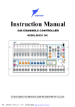
Instruction Manual
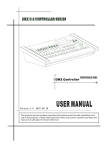
192 CHANNELS CONTROLLER
MODEL:DISCO 192
GUANG ZHOU FLY DRAGON LIGHTING EQUIPMENT CO., LTD
PDF 文件使用 "pdfFactory Pro" 试用版本创建 www.fineprint.com.cn
- 1-
CONTENTS
1. PARAMETER INDEX ··············································································································· 2
2. POINTS OF ATTENTION FOR SAFETY USE ········································································· 2
3. PACKING LIST ························································································································· 2
4. COMMUNICATION CABLE ···································································································· 3
5. DMX 512 ADDRESS DISTRIBUTION ······················································································ 3
6. DISGRAM FOR COMMUNICATION CABLE CONNECTING LINE & PULL-UP CODE
OF ELECTRONIC LIGHT ADDRESS CODE··········································································· 4
7. INDICATING DIAGRAM FOR MASTER BOARD AND FUNCTIONAL DOMAIN ················ 5
8. DIRECTIONS FOR MASTER BOARD FUNCTIONAL AREA ················································ 6
9. DIRECTIONS FOR DOUBLE FUNCTION KEY······································································ 7
10. DIRECTIONS FOR INFORMATION DISPLAYED ON LCD LIQUID CRYSTAL
SCREEN ·································································································································· 8
11. EDITTING FOR ELECTRONIC LIGHT PROGRAM(FIELD) ············································ 9
12. RUNNING FOR ELECTRONIC LIGHT PROGRAM ······························································· 9
13. SHOWING ON SPECIAL SCENE ··························································································· 10
14. HOW TO DISPOSE AND REMOVE THE POTENTIAL REGULATOR OF JOY STICK ······ 10
Note: As the company pursues a policy to improve its products all the time, the data contains in
this
manual are subject to change without notice. The Our Company reserves the right to change the
relevant specifications in product improvement. The publisher of this manual shallnot be responsible
for the accuracy of the information herein contained or the consequence resulting from such
information.
PDF 文件使用 "pdfFactory Pro" 试用版本创建 www.fineprint.com.cn
-2 -
Many thanks to you for your use of FLY DRAGON INTELLIGENT LIGHTING
SERIES CONTROLLOR! The console of Disco 192 is used for DMX 512 Signal Output
made according to the international standard. Please carefully read the manual before
you operate it.
1. PARAMETER INDEX
Standard of Signal Output
DMX 512 International Standard
Number of Total Channel
192 Routes
Number of Controllable Intelligent
Lights
12 Sets
Maximum Channels of Controllable lights
16 channels
Number of Programs (field)
12 Fields
Maximum Number of Steps for Program(scene)
40 Steps
Total Steps (scene) of Program
480 Steps
Pausing Time on Scene
0.1-25.5 Second/step
Gradual Changing Speed on Scene
0.1-25.5
Display Screen
LCD Liquid Crystal Display Screen and
16x2 Character
DMX 512 Outlet Interface
Points-Plug & Socket of 3-core XLR
Storing Capacity
Memory Card of L-capacity 128K
Input Voltage
AC220V, 50HZ-9V/1000MA
Dimension
483MM(L)*178MM(W)*80MM(H)*
Weight
3.3 kg
2. POINTS OF ATTENTION FOR SAFETY USE
· The console must be connected to the main grounding.
· To avoid to put on or off the plug of the communication cable as power is on.
· Order for starting machine: Please to first switch on the controllable power of all the electronic
lights; then switch on the power of controller otherwise damage the controller.
· Pay attention to damp-proof, water-proof, dust-proof and anti-electrostatic, and periodically
service and clean it.
3. PACKING LIST
·
·
·
·
Disco 192 Console
DMX 512 Power Cable
Manual of Disco 192
Power Transformer
1 set
1 piece
1 copy
1 piece
PDF 文件使用 "pdfFactory Pro" 试用版本创建 www.fineprint.com.cn
- 3-
4. COMMUNICATION CABLE
·Use the double-stranded and shielded cable with impedance 120 ohm. If the cable length is more
than 200 meters or light number is excessive, the signal booster amplifier should be used, and
terminal end resistor (120 ohm/1 w) must be fixed to the last light.
·One core of communication cable must be connected to ground (GND), the second to negative
signal while the third one to signal positive. No vice versa, no false welding.
·A single end of communication cable must be connected to earth for shielding.
·The communication cable must be avoided to lay together with the strong voltage cable.
5. DMX 512 ADDRESS DISTRIBUTION
The console of Disco 192 applies 1-192 channel of DMX 512, and is capable to control the
intelligent lights within 16 channels. The address distribution is shown as follows:
S. №
light
of
DMX Starting & Ending Add of lights
When using Disco 192
Decimal System
Switch Position of light Add.
1
1
1
ON
2
17
1,5
ON
3
33
1,6
ON
4
49
1,5,6
ON
5
65
1,7
ON
6
81
1,5,7
ON
7
97
1,6,7
ON
8
113
1,5,6,7
ON
9
129
1,8
ON
10
145
1,5,8
ON
11
161
1,6,8
ON
12
177
1,5,6,8
ON
PDF 文件使用 "pdfFactory Pro" 试用版本创建 www.fineprint.com.cn
-4 -
6. DIAGRAM OF COMMUNICATION CABLE CONNECTING LINE AND PULL
-UP CODE OF INTELLIGENT LIGHT ADDRESS CODE
PDF 文件使用 "pdfFactory Pro" 试用版本创建 www.fineprint.com.cn
- 5-
7.
INDICATING DIAGRAM OF MASTER BOARD AND FUNCTIONAL DOMAIN
PDF 文件使用 "pdfFactory Pro" 试用版本创建 www.fineprint.com.cn
-6 -
8. DIRECTIONS OF MASTER BOARD FUNCTION DOMAIN
S №
1
2
Name
Power Switch
Power switch is inside the controller. If it is demanded to turn off the power
of the whole machine, please pull off the external power plug of transformer.
[BLACK] Switch Button
of Signal Outlet
Change over to cut-light and running state
·LED is on: It is in light cutting state and all the output signal value of
DMX is 0.
·LED is off: It is in normal output signal state
[EDIT/RUN] Edit and Run
Change over into editing or running state
·LED is on: It is in edit-programming state. That may edit 12 programs
(field) and each field can reach the scene of 40 steps.
·LED is off: The program is running.
[SHIFT] Turn Over Key of
Channel
·When the green indicator is off, it is to show that the channel push-pull
area is controlling 1-8CH corresponding data.
·When the green indicator is on, it means the channel push-pull area is
controlling 9-16CH corresponding data.
[P1-P12][PCH9-PCH16]
Digital Push-pull Button
Area
At a time when in programming state, it is used to select the program (field)
№ and to choose the controllable light №. When coming into programming
state, firstly press the key to select the program (field) № being edited. As
press the key area, it means that the light under control has been selected.
·When running the program, it is to select the edited program (field) №.
·At a time when coordinating to use the function key, it applies to change
the selecting state of the corresponding channel or to make a choice of the
corresponding light №, and to withdraw the front 12 individual scenes
from No 1 program (field), etc.
Double-function
Push-button Area
Apply it to the programming state. When in program running state, there is a
different definition. For the details, please refer to the directions of
double-function key.
[CH1-8][PCH9-16]
Channel Data Regulating
Push-pull Area
Adjust and choose DMX value of electronic light corresponding to each
channel for regulating and selecting the various design and color effects of
apparatus.
X, Y Direction, Joy Stick
It is used to dispose X, Y direction scene control channel. Push [SET X,Y]
functional key to input P1-P8 or PCH9-PCH16 keys of X, Y scan channel of
apparatus, then press [SET X,Y] TO WITHDRAW memory.
[SPEED][CROSS] Speed,
Time, Control Push-pull
Lever
·SPEED Potential regulator: Regulate running program (field) of pausing
time on scene for use of programming and running.
·CROSS Potential Regulator: Adjust the running speed of gradual change
on scene for use of programming and running.
·AUTO Area below potential regulator: It is used to automatically carry out
the programmed scene pausing time and running speed. The part above
the potential regulator is to change running speed and scene pausing time
by hand at random.
LCD 16x2 Liquid Crystal
Indicator Area
For the state indicating every showing data, please refer to the directions of
liquid crystal display information.
3
4
5
6
7
8
9
10
Function Description
PDF 文件使用 "pdfFactory Pro" 试用版本创建 www.fineprint.com.cn
- 7-
9. IRECTIONS OF DOUBLE-FUNCTION KEY AREA
[DELETE]
Delete
EDIT
Area
[3-]Reduce
Scene Step
[+4] Increase
Scene step
[SET X,Y] Set
up the Scan
Channel
[CLEAR] Clear
Key
RUN
Area
[CROSS
MODEL] Select
Operation Model
[SCENE] Run
Special Scene
[RELEASE
CHANNELS]
[MANUAL]
Select by Hand
When programming, it is used to cancel a program or program step, remove and
shift a channel display.
·Instantly press: Cancel the present program step.
·Press for 3 Second: Delete the present program step in order to vacate.
·Under the Set-up of [SET X,Y], press [DELETE] key to cancel X,Y running
direction channel shift.
Turn page back of programming time and view the upper step scene.
Turn over page of programming time to memory the present scene (add a scene
step) or check the programmed scene.
Press [RUN/EDIT] key to switch on the corresponding LED indicator; then press
[SET X,Y] key again. According to the instruction on liquid crystal screen, choose
two scan channels of X,Y running direction corresponding to electronic light to
change onto the rock lever potential regulator for controlling. The yellow indictor
will immediately shine; then again press [SET X,Y] key to memory and withdraw.
·By pressing [CLEAR] key, it can clear the selecting state of digital key. It is
convenient for repeating the selection.
·By pressing [CLEAR] key, it can clear off all the channel-function data
immediately after pressing this key, and all of that come to zero.
·Model 1: When running a program, all of the channel data run under the control
of potential regulator along with the scene transition time.
·Model 2: When running a program, the set-up X, Y channel data are under the
control of potential regulator along with scene transition time while other
remained channel data are all in jumping change. Thus the various non-edited
and stored patterns are likely not to be revealed during the slow scanning.
When running a program (field), press the key and in no time choose [P1-P12]
key; accordingly move the front 12 scenes out from № 1 program (field), which
could show out independently for use of special scene. If want to withdraw the
scene show state, please press [EDIT/RUN] key.
·Press [RELEASE] key, then again coordinate with [P1-P12] key to press SHIFT +
(PCH 9-PCH 16) key. It is likely to change the data of (CH1-CH16) channel
during running a program, which is the corresponding status data to be read or
selected at random, and also are the disposed state data in reading and selecting
program. Repeat pressing [RELEASE] key in order to store the disposed state
and withdraw.
·( O represents that CH1-16 channel data is under the control of push-pull as
operating by manual and F represents the channel data is running automatically
following program.)
When running a program, press [MANUAL]key, again press any key in [P1-P12]
to choose the apparatus № being set in manual state. Then again, push the
released channel for achieving the effect of MANUAL + AUTOMATIC controlling
light at random.
PDF 文件使用 "pdfFactory Pro" 试用版本创建 www.fineprint.com.cn
-8 -
10. DIRECTIONS OF INFORMATION DISPLAYED ON LCD LIQUID CRYSTAL SCREEN
Display
FLY DRAGON
DISCO 192
RUN Chase [??]
[01] [00.0][00.0]
RUN Chase [??]
CH**1—[***] or
X→[***]Y→[***]
RUN
SCENE
SELECT P1-P12
EDIT Chase [??]
CH [10] [**]
EDIT Chase [??]
CH [**]→[***] or
X→[***] Y→[***]
EDIT Chase [??]
SPEED → [***] or
CROSS→[***]
EDIT Chase [??]
STEP [01][**]
12345678FFFFFFF
FA or FFFFFFFFB
Set: X-Y
X,[]
Y:[]
MANUAL
FFFFFFFFA
FFFFFFFFB
[??]
or
Concrete Information
Name of company, Model and Edition №
Press [EDIT/RUN] key, the corresponding indicator is off. It means the console is in
waiting state for command. The question mark Chase [??] refers to the program (field)
№ for waiting input. [01] [00.0]and [0.00] represent the scene step mark, scene pausing
time and scene gradually changing speed in order.
The upper line represents the running program (scenes) while the lower line the
channel № and channel data.
It represents the front 12 scenes as running № 1 program (scene). Select by press
[P1-P12] digital key.
Press [EDIT/RUN] key to turn on the corresponding indicator, which means the console
is in editing state.
?? in Chase [??] is to show the program № waiting for command.
STEP [01] is № of scene step that will be changed by operating [3- or +4] key. When
** displayed inside the last [ ], it refers to that the scene step is the last step in the scene.
When [ ] is blank, that means there has been already the scene data.
The upper line refers to the editing program № while the lower line the scene pausing
time or transition time.
The upper line means the editing program № while the lower line the scene pausing
time or transition time.
Press [EDIT/RUN] key to put on the corresponding indicator, that means the console is
in editing state.
?? in Chase [??] represents the editing program № waiting command.
STEP [01] is № of scene step that will vary according to operating [3- or +4] key.
When ** is displayed in the last [], it means the scene step is the last step in the scene.
Press [CHANNELS] key to display the left of interface. The lower line number are
indicating the state of eight corresponding basic control channels (1-8 channels can be
identified by their suffix A while 9-16 channels by their suffix B.) F or O in the lower
line is to respectively indicate the corresponding channels belonging to the kind of
automatic or manual operation, i.e., if they can be released. Among which, F refers to
non-releasing. And it can be changed through the corresponding [P1-P8] key or by
pressing [SHIFT] key + [PCH 1-PCH 16].
As just entering editing state, press [SET X, Y] key to display the left prompt.
X: [ ] Y [ ] are vacant brackets. Press [P1-P8] key or [SHIFT]+(PCH9-PCH16) to input
the channel № being transferred onto the joy stick control, or press [DELETE] to cancel
the set up channels.
Under the state of running a program, press [MANUAL] key to show the left prompt.
The sign of [??] in upper line means the running program (scene) № while in the lower
line is to display 1-16 channels (1-8 channels are identified by suffix A while 9-16
channels, by suffix B) whether they are in the state of release. Among that, F represents
that the corresponding channels have not been released while O means that the release
has not been set. Again press [P1-P12] key to select one set many sets of apparatus for
carrying on the manual operation to the released channels.
Re-press [MANUAL] key once to withdraw the blend control of manual and automatic
operation and to carry on the automatic operating program.
PDF 文件使用 "pdfFactory Pro" 试用版本创建 www.fineprint.com.cn
- 9-
11. EDITING OF INTELLIGENT LIGHT PROGRAM (SCENE)
(1)
(2)
(3)
Press [BLACK] key to turn off LED.
Press [EDIT/RUN] key to switch on LED for entering programming state.
Press any key in digital keys[P1-P12] for selecting editing program № to display it in Chase [ ] of
LCD.
(4) Re-press digital key [P1-P12] to select the controlled intelligen light and to switch on the
corresponding LED. If the corresponding indicator failed to shine, that means LED has not been
selected and is not affected by the fifth step.
(5) Push [CH1-CH8] to regulate each of the corresponding channel data of fixtures or press [SHIFT] key
and push [CH9-CH16] for search the corresponding effect of apparatus (If the scan channel shift of
X, Y moving direction has been set, so two straight sliding rods of potential regulator are out of
function. You might operate the rocking potential regulator at the lower end of right side to obtain
the data.
(6) Repeat Step 4 and 5 to regulate other apparatus for achieving the expected effect needed in the scene
of fixtures
(7) Push [SPEED] [CROSS] potential regulator to adjust the scene pausing time and transition time
well.
(8) Press [+4] to memorize this scene effect and enter the next editing program ( view the upper
scene by pressing [3-] key.). Repeat Step 4,5,6 and 7 revision, then memorize again.
(9) Repeat Step 4 – 8 to program other scenes (program step).
(10) Press [EDIT/RUN] key to switch off the corresponding indicator to memorize and withdraw from
editing state for entering operating state.
(11) Repeat Step 2-10 to edit other program (scene).
12. RUNNING FOR INTELLIGEN LIGHT PROGRAM
(1)
(2)
(3)
(4)
(5)
(a)
(b)
Press [EDIT/RUN] key to switch off LED indicator.
Press the digital key [P1-P12] to select the program (scene) № for operating. If the program has not
been edited, the corresponding LED will not shine as the key is pressed.
Regulate [SPEED] potential regulator to change the pausing time between scenes and vary the scene
gradual running speed. If [SPEED] or [CROSS] potential regulator is in lower part of AUTO area.
The AUTO will run the edited scene pause and scene transition time.
Press [CROSS] key. It is capable to change the running model. For the details, please refer to Part 9:
Directions for Double-function Key Area.
If running a program by manual or by auto-joking operation, please following the set-up steps in the
below:
First to release the channel: Press [CHANNELS] key, then press [P1-P8] key (or press [SHIFT] key).
Again press [PCH9-PCH 16] for releasing the corresponding channels to change F into O. At last to
press [CHANNELS] key again to memorize and withdraw. (F: represent the corresponding
channels. During the running of a program, the manual data will not be accepted and controlled by
the edited program. O: refers to that the corresponding channels have not been controlled by the
program, but accept the manual push-pull data).
Select the light to be operated for releasing the channels: Press [MANUAL] key and again press
[P1-P12] key to select the light signal to be operated by hand; push the corresponding released
push-pull of potential regulator at random to carry on manual + auto joking running program.
PDF 文件使用 "pdfFactory Pro" 试用版本创建 www.fineprint.com.cn
-10 -
Withdraw the selection of manual by way of pressing [MANUAL].
(17) Press [BLACK] key to run the program (scene) to select Pause/Start. When the corresponding LED
is shining the pause outputs. When LED
is off the output running is normal.
(18) OWING OF SPECIAL SCENE
Under the state of program running (i.e., the corresponding indicator of [RUN/EDIT] is off, press
[RUN/SCENE] key, then press any key in [P1-P12] again. It is likely to select the front 12 scenes
in the edited No 1 program. Therefore, it is suggested that the front 12 scenes of No 1 program
(scene) are better to have a special definition to achieve the effect of stunt showing as it is in
programming.
(19) OW TO SET UP AND CANCEL JOY STICK POTENTIAL REGULATOR
Set-up of joy stick potential regulator: Press [RUN/EDIT] key to switch on the indicator. Then,
press [SET X, Y] key immediately. According to the display on screen, select two corresponding
scene channels of apparatus X, Y moving direction from [P1-P8] or press [SHIFT] key from
[PCH9-PCH16] to shift onto joy stick potential regulator for controlling, so the green indicator is
shine instantly. If any error occurs by inputting , press [DELETE] key to cancel the input and
repress the correct corresponding channels, then again press [SET X, Y] key to memorize and
withdraw.
Cancellation of Set-up for Joy Stick Potential Regulator: Press [EDIT/RUN] key to switch on
the corresponding LED, then, press [DELETE] key to clear the input data. As the green indicator
is off immediately re-press [SET X, Y] key to memorize and withdraw.
PDF 文件使用 "pdfFactory Pro" 试用版本创建 www.fineprint.com.cn