1
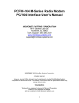
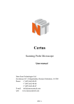
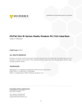
Scanner control console
User’s Manual
0
Table of contents
1.
Parameters…………………………………………………..………....1
2.
Safety use cautions…………………………………………………….2
3.
Contents in the package………………………………………………..2
4.
Communication cable…………………………………………..…...…2
5.
DMX512 address distribution……………………………………….…3
6.
Diagram of the communication cable link and scanner address set…...4
7.
Diagram of the panel and functional areas……………………….……5
8.
Explanation of functional area of the panel………………………..…..5
9.
Explanation of the duplex key area…………………………………….7
10. Explanation of the display information on the LCD…………………...8
11. The editing of scanner chase………………………………………..….9
12. Running of scanner chases…………………………………..………..10
13. Special scene presentation…………………………………………….10
14. How to set and cancel the joystick potentiometer………………….....11
15. Conventional dimmer control………………………………………....11
1
Thanks for using Disco240 scanner console! Disco240 console has
internationally standard DMX512 signal output. Before operation,pl ease refer
to the user’s manual carefully.
1. Parameters
Output signal specifications
DMX512 international standard
Total number of channels
192 channels
Number of scanners
24 scanner
Max. number of channels for the scanner
16
Number of chases(scenes)
12 chase
Maximal number of chase steps(scene)
40 steps
Total number of chase steps(scene)
480 steps
Scene pause time
0.1-25.5 second/step
Scene cross speed
0.1-25.5 seconds
Dimmer channel
24 channels
Display screen
LCD display, 16×2 characters
DMX512 outputs interface
3-core XLR pin socket and socket
Memory capacity
128 K high capacity memory card
Input voltage
50 / 60HZ—5V / 2000MA
Volume
483mm×178mm×80mm
80mm
Weight
3.25Kg
2
2. Safety use cautions
The console must be connected to the safety earth line.
Never pulling out or inserting the communication cable with electricity.
Start order:Please turn on all the controlled scanner power suppies first,and
then turn on the controller power,otherwise the controller is easy to be destr
Oyed.
Prevent it from damp,water,dust, static, and maintain and clean it regularly.
3. Contents in the package
Disco240 console
1
DMX512 cable
1
Disco240 user’s manual
1
Power adapter
1
4. Communication cable
It adopts the twisted screened wire with the specified impedance of 120
ohms, and if the cable exceeds 200 meters long or there are too many
scanners, a signal amplifier should be added, and a terminal resistor should
be added to the last scanner(120ohms/1W).
The Pin 1 of the communication cable is the grougding (GND), Pin 2 is
negative signal, and Pin 3 is positive signal; they should not be inversely
connected, and should not be coldly welded.
The communication cable should be screened by single-terminal earthing.
The communication cable should not be wired together with strong
electricity.
3
5. DMX512 address distribution
Disco240 console uses 1 to 240 channels of DMX512,so it can control the
scanners with no more than 16 channels. The address is distributed as follows:
Scanner DMX starting address
Scanner serial number
When using Disco240
Decimal system
Scanner address switch location
1
1
1 ON
2
17
1,5 ON
3
33
1,6 ON
4
49
1,5,6 ON
5
65
1,7 ON
6
81
1,5,7 ON
7
97
1,6,7 ON
8
113
1,5,6,7 ON
9
129
1,8 ON
10
145
1,5,8 ON
11
161
1,6,8 ON
12
177
1,5,6,8 ON
P13-P24
206-217
Dimmer channel 1-24
218-241
4
6.Diagram of the communication cable link and scanner addree dial
Terminal resistance: 120ohms/1W
No.12 Scanner:
Disco 240
Scanner control console
No.8 Scanner:
No.7 Scanner:
No.6 Scanner:
No.5 Scanner:
No.4 Scanner:
No.3 Scanner:
No.2 Scanner:
No.1Scanner:
5
8.Explanation of functional area of the panel
Serial
Numbe
1
2
3
4
5
6
Name description
Function explanation
Controller internal mains switch; if the power supply of
the whole machine needs to be turned off , please pull out
the external power adaptor.
Change the light converting and operation state
LED is on: light converting,all the output DMX
BLACK
signals are 0.
LED is off: Normal signal output state.
Change edit/running state
LED is on:Editing program state; it can edit 12
EDIT/RUN
chases,up to 40 steps for each chase.
LED is off: Running the chase.
When the indicating light is off, it indicates the data
corresponding to the channel slider area scanner.
Scanner dimmer selection key
When the indicating light is on, it indicates the data
corresponding to the channel slider area scanner.
When the indicating light is off, it indicates
Distributed control centralized
distributed control.
control selection key
When the indicating light is on, it indicates
centralized control.
P1-P12
In the program state, it is used to select the number
PCH9-PCH16
of the chase and to select the number of the
Number key area
controlled scanner.
POWER
6
7
Dimmer point control area
8
Duplex button area
9
Page turning 1
10
Page turning 2
11
Page turning 3
12
Rocker
In the program state, press this key area once, and the
chase number to be edited is selected; press this
key area again, and the scanner to be controlled is
selected.
When running the program, it is used to call out the
edited chase number.
When it is used in coordination with the functional
key, it is used to change the selection state of the
corresponding channel, or select corresponding
scanner number, and call out the 12 independent
scenes in No.1 chase.
206 to 217 channel outputs of the point controlled
dimmer.
When applied in the prpgram state and the running
program state, it has different function definitions. Please
refer to the explanation of the duplex key for details.
Press this key, when the indicating light is on, the slider
area is corresponded to CH1—CH8
Press this key, when the indicating light is on, the slider
area is corresponded to CH9—CH16
Press this key, when the indicating light is on, the slider
area is corresponded to CH17—CH24 (only valid in the
dimmer state).
Used to control the XY scanning channel of the scanner.
13
SPEED. CROSS
(Program time control)
14
LCD
15
CH-8 PCH9-16
(Channel data slider area)
16×2
SPEED potentiometer: adjust the chase pause time in
running program, for use in program and running.
CROSS potentiometer: adjust the chase cross speed,
for use in program and running.
The AUTO area in the bottom part of the
Potentiometer: used to automatically implement the
programmed chase pause time and running speed, the
upper part is used to manually and randomly change
the program running speed and chase pause time.
The state indicates the indicating data; see to the LCD
information for details.
Adjust and select the DMX values corresponding to the
channels of the scanner and dimmer; used to adjust and
select the different functions of the scanner.
7
9. Explanation of the duplex key area
[DELETE]
EDIT
area
[
-]
[+
]
[SET X/Y]
[CLEAR]
[CROSS MODE]
RUN
area
[SCENE]
[RELEASE CHANNELS]
In program state, it is used to delete the chase or chase
step, and cancel the setup of the transfer channel.
Instantly press down: Delete the current chase step.
Press down for 3 seconds: Delete the current chase step, and
make it an empty program.
In the state of [SET X/Y] setting,pressing the [DELETE] key
will cancel the X-Y direction channel transfer.
In program state, it is used to turn to the previous page, to
view the last chase.
In program state, it is used to turn to the next page, to
memorize the current chase (adding a chase step) or to view
the edited chase.
When just entering the edit state , immediately press [SET
X/Y], and according to the prompt on the LCD, select two
scanning channels corresponding to the scanner X-Y
direction from P1-P8 or PCH9-PCH16, and transfer to
control the yellow indicating light with the rocker
potentiometer, and then immediately press the [SET X/Y]
key again to memorize it and quit.
In any number key selection state in the running mode,
press [DELETE], and then immediately clear the
indication; it can be repeatedly selected.
In the running mode, all channel function data are
cleared to zero after pressing this key.
Mode 1: When running the program, all the channel
data are running with the chase cross time
potentionmeter control.
Mode 2: When running the program, the set X and Y
channel data is controlled by the chase cross time
potentiometer, and all the other channel data are in the
jumping state, so as to prevent the colors and patterns
that have not edited or memorized from playing in slow
scanning.
When running the chase, press this key, and then
immediately select P1-P12, to call out the first 12 scenes in
No.1 chase, which are independently presented to be used as
special scenes. In order to quit the scene presentation state,
please press the [EDIT/RUN] key.
Press this channel release key, in coordination with
P1-P8 keys or SHIFT+(PCH9-PCH16) keys, will change
the data of channels CH1-CH16, in running the program,
8
[MANUAL]
whether to randomly read the state data corresponding to
the potentiometer or to read the state data the program
has already set. Press the [RELEASE] key once again, to
store the set state and quit.
(O indicates the CH1-CH16 channel data is controlled
by the manual slider, and F indicates that the channel
data automatically runs with the program.)
When running the chase, press [MANUAL], and then press
any key of (P1-P12), to select the scanner number to be in
the manual state, and then slide the released channel, and
then the dimmer effect can be controlled both manually and
automatically.
10. Explanation of the display information on the LCD
Display
Specific information
DISCO 240 V3.0A
Company name, model and version number
S/N:0020-02-2727****
TEST OK
Sequence Number and test condition
RUN Chase [??]
[01] [00.0] [00.0]
Press [EDIT/RUN], the corresponding indicating light will be off,
indicating the console is in the running standby.
The ?? in Chase [??] indicates the chase number to be input, [01]
[00.0] [00.0] are respectively the chase step numbers, the chase pause
time, and chase cross speed.
RUN Chase [??]
CH[**]
[***]
or
X
[***] Y
[***]
The upper line indicates the running chase, and bottom line indicates
the modified channel number and channel data.
RUN SCENE
SELECT P1—P12
EDIT Chase [??]
CH [01] [**]
EDIT Chase [??]
CH[**] [***]
or X
[***]Y
[***]
EDIT Chase [??]
SPEED
[***]
Press the number key of P1-P12 to select the first 12 scenes that
represent the No.1 chase.
Press [EDIT/RUN], to have the corresponding indicating light on,
indicating the console is in the edit state.
The ?? in Chase [??] indicates the chase step, which can change with
the operation of [
-]or[+
]When the final [ ] shows **
in it, it indicates that chase step is the last step in this chase.
When [ ] is empty, it indicates that there have been already chase
data.
The upper line represents the chase number to be edited, and the
bottom line rpresents the modified channel number and the channel
value.
The upper line represents the chase number to be edited, and the
chase pause time or chase cross time.
9
or CROSS
[***]
EDIT Chase [??]
STEP [01] [**]
12345678
F FF FF FF FA
or F F F F F F F F
B
Set: X-Y
X: [ ] Y: [ ]
MANUAL: [??]
F FF FF FF FA
or F F F F F F F F
B
Press[EDIT/RUN], to have the corresponding indicating light on,
indicating the console is in the edit state.
The ?? in Chase[??] represents edited chase number to be run.
STEP [01] is the serial number of the chase step, which can change
with the operation of[
-]or[+
]When the final [ ] shows**
in it, it indicates that chase step is the last step in this chase.
Press [CHANNELS] to show the left interface. The bottom line
number indicates the state of the 8 corresponding basic control
channels (Channels 1 to 8 are identified with the suffix A, and
channels 9 to 16 are identified with the suffix B), and the bottom line
F or O respectively indicates whether the channel of the
corresponding row is automatic or manual, i.e., whether it is released.
Here, F indicates unreleased, which can be changed by pressing the
corresponding P1 to P8, or pressing [SHIFT] +(PCH9-PCH16).
When just entering the editing state, press [SET X/Y] will show the
prompt on the left.
X: [ ] Y: In the space, the channel number to be transferred to the
rocker control can be input by pressing P1-P8 or pressing [SHIFT]
+(PCH9-PCH16), and you can also press [DELETE], to cancel the
set transfer channel.
In the state of running the chase, pressing[MANUAL], will show the
prompt on the left.
The[??] in the upper line shows the chase number that is running, and
the bottom line shows whether the 1-16 channels (channels 1-8 are
identified with suffix A, and channel 9-16 are identified with suffix
B) are released. Here, F indicates the corresponding channel is
released, and O indicates it has not been released. Press P1-P12 again
with select one or more scanners to conduct the manual operation of
the released channels.
Press [MANUAL] again, will quit the mixed control of manual+
automatic, and then carry out the automatic program.
11. The editing of scanner chase
1. Press [BLACK], to turn on the LED;
2. Press [EDLT/RUN], to turn on the LED, and enter the program state;
3. Press any one of the number keys (P1-P12) once, to select the chase number
10
to be edited, which is shown in Chase [ ] on the LCD.
4.
The press numbers (P1-P12), to select the controlled scanner, and its
corresponding LED will be on. If the corresponding indicating light is not on,
then that scanner has been selected, so it will not be affect by Step 5.
5. Slide (CH1-CH8) to adjust the corresponding channel data of the scanner, or
press [SHIFT] and slide CH9-CH16 to call out the corresponding scanner
effect
(if you have set X and Y direction scanning channel transfer, then two direct
sliding potentiometer sliders will not function. You can control the bottom
right rocker potentiometer to get the data).
6. Repeat steps 4, and 5 to adjust other scanners, so that the needed scanner chase
can reach the predefined effect.
7. Slide [SPEED] and [CROSS] potentiometers, to adjust the chase pause time
and chase cross time.
8. Press [+
], to memorize this chase effect, and enter the next step of
editing.(Press [
- ], can view the last chase, repeat modification in steps
4,5,6 and 7, and press [+
] again to store it).
9. Repeat steps 4 to 8, to edit other chase.
10.Press [EDIT/RUN], to have the corresponding indicating light on; memorize it
and then quit the editing state, to enter the running state.
11.Repeat steps 2 to 10, to edit other chase.
12. Running of scanner chases
1. Press [EDIT/RUN], to have the corresponding LED on.
2. Press number keys (P1-P12), to select the chase number, and make it run; if
that chase has not been edited, then the corresponding LED will not be on
when that key number is pressed.
3.
Adjust [SPEED] and [CROSS] potentiometers, to change the inter-chase
pause time and the chase cross speed; if the [SPEED] or [CROSS]
11
potentiometer is in the bottom AUTO area, then the chase pause time and
chase cross time that had already been edited will be run.
4. Press [CROSS MODE], to change the running mode; see 9.explanation of the
duplex key area for details.
5. If you want to carry out the mixed running program of manual and automatic,
you can set the running according to the following steps.
a). First, release the channel: Press [CHANNELS], and then press (P1-P8) (or
press [SHIFT], and then press PCH9-PCH16), to release the corresponding
channel, and F will be changed to O; at last, press [CHANNELS], to
memorize it and quit. (F: indicates that the corresponding channel will not
take manual data in chase running, and is controlled by a programmed chase.
O: indicates the corresponding channel is not controlled by the chase in chase
running, and it will take manual slider data).
b). Select the scanner that will run the release channel: Press [MANUAL],
and then press (P1-P12), to select the scanner light to be manually controlled.
Randomly push the corresponding released potentiometer slider to carry out
mixed running program of manual + automatic, then press [MANUAL] to
quit the manual option.
6. Press [BLACK] can make pause/start selections for the running chase; when
LED corresponding to the key is on, then output is paused, and when the
LED is off, then the output is run normally.
13.
.Special scene presentation
In the state of running chase (i.e., the indicating light corresponding to
[RUN/EDIT] is off), press [RUN SCENE], and then press any key of P1-P12, will
call out the first 12 scenes in the programmed No. 1 chase. Therefore, we suggest
that in that in program state, the first 12 scenes in No. 1 chase should be specially
defined, which can make some special effects.
12
14. How to set and cancel the rocker potentiometer
Set the rocker potentiometer settings: Press [RUN/EDIT], to light the indicating
light, and then press [SET X/Y] immediately; according to the prompt on the LCD,
select two scanning channels corresponding to the scanner X and Y direction from
(P1-P8) (or from PCH9-PCH16 by pressing SHIFT), shift to use the rocker
potentiometer to control the green indicating light, and the light is on immediately.
In case of wrong input, press [DELETE] to cancel the input, and input the correct
corresponding channel, and then press [SET X/Y] again to memorize it and quit.
Cancel rocker potentiometer settings: In the state of [SET X/Y], press
[DELETE] to clear the input data, and the green indicating light turns off
immediately; and then press [SET X/Y] again to memorize it and quit.
15. Conventional dimmer control
Point control: Press P13-P24 to control the dimmer 206-217 channels, and when the
indicating light is on, the output is 100%, and when the indicating light is off, the
outputs is 0%.
Distributed control: In the state of non-programming, press SCAN/LIGHT to make
the indicating light turn on; enter the dimmer state, select the channel page of
dimmer control by pressing SA/SB/SC, and push the different sliders in the slider
area to adjust the dimmer output.
13