1
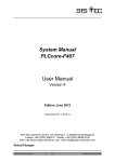
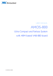
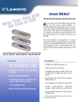
DAM-C3220 CAN Repeater
User’s Manual
Beijing ART Technology Development Co., Ltd.
DAM-C3220 User’s Manual
V6.012
Contents
Contents ................................................................................................................................................................................2
Chapter 1 Overview ..............................................................................................................................................................3
Chapter 2 Hardware Description..........................................................................................................................................4
2.1 Hardware Layout.....................................................................................................................................................4
2.2 Main Components Function....................................................................................................................................4
2.2.1 CAN Communication Interface ...................................................................................................................4
2.2.2 Indicator .......................................................................................................................................................5
2.2.3 Termination resistor .....................................................................................................................................5
2.3 CAN Bus Connection Device .................................................................................................................................6
2.3.1 Branch Connection.......................................................................................................................................6
2.3.2 Extension Connection ..................................................................................................................................6
2.4 Transmission Cable.................................................................................................................................................6
2.5 Drive Capability and Baud Rate .............................................................................................................................7
Chapter 3 Hardware Description..........................................................................................................................................8
3.1 Application Connection ..........................................................................................................................................8
3.2 Hardware Installation ..............................................................................................................................................8
Chapter 4 Notes and Warranty Policy ................................................................................................................................10
4.1 Notes .....................................................................................................................................................................10
4.2Warranty Policy .....................................................................................................................................................10
2
DAM-C3220 User’s Manual
V6.012
Chapter 1 Overview
DAM-C3220 is a CAN bus data repeater device, compatible with CAN bus standard, can extend the distance
communication of the CAN bus network, and increase the equipment number of CAN bus network.
DAM-C3220 supports CAN2.0A and CAN2.0B protocol, compatible with ISO 11898-2 protocol, there are two CAN
interfaces, two optical isolators and two termination resistors, each CAN interface can drive 100 nodes, the
communication speed up to 800Kbps, use differential signal transmission, with long-distance anti-jamming
communication capability, can realize data communication in long-distance and harsh environment.
DAM-C3220 built-in optical isolator, provide 2500Vrms isolation voltage, achieve the device and power to isolate, can
effectively prevent the lightning and interference.
Module Features
¾
Voltage Input Range: +10V~+30V
¾
Supports CAN2.0A and CAN2.0B protocol
¾
Compatible with ISO 11898-2 protocol
¾
Network Topology: tree, star
¾
Communication Rate: up to 800Kbps
¾
Signal Delay: 200ns
¾
Drive Capacity: 100 nodes (each CAN interface)
¾
Opto-isolation: 2500Vrms
¾
Power Consumption: 2W (max)
¾
Integrated terminal impedance 120R (can be removed by jumper)
¾
Operating Environment: -25 ℃ to 75 ℃, relative humidity 5% to 95%
¾
Dimension: 122 mm x 72 mm x 35 mm
3
DAM-C3220 User’s Manual
V6.012
Chapter 2 Hardware Description
2.1 Hardware Layout
2.2 Main Components Function
2.2.1 CAN Communication Interface
10-pin cable definition
Pin
Name
Function
1
CANH1
The first channel CANH signal line.
3
CANL1
The first channel CANL signal line.
5
GND1
The first channel CAN signal reference ground.
7
EARTH1
Protected.
9
V+
The positive of power input.
10
V-
The negative of power input.
14
EARTH2
Protected.
16
GND2
The first second CAN signal reference ground.
18
CANH2
The second channel CANH signal line.
4
DAM-C3220 User’s Manual
20
CANL2
V6.012
The second channel CANL signal line.
2.2.2 Indicator
RUN: running lights. Flashing for data transfer, and the flash frequency changes with the speed of data transfer rate.
POWER: Power Indicator. On for normal.
2.2.3 Termination resistor
DAM-C3220 has two internal jumpers JP1 and JP2, used to select the termination resistor of 1-ch and 2-ch CAN signals.
When the jumper pins 2-3 shorted, it will automatically access the 120Ohm (internal) termination resistor, when 1-2 pins
are shorted, do not access the termination resistor.
Termination Resistor
JP1
JP2
120Ohm (internal)
No termination resistor
Note: To change the status of the jumper JP1/JP2, we should open the case.
Users can also use external termination resistor. The termination resistor between CANH and CANL signals equivalent
to 60ohm, if not select the internal termination resistor, the external resistor application is shown as the following.
5
DAM-C3220 User’s Manual
V6.012
2.3 CAN Bus Connection Device
DAM-C3220 receives data from CAN1 and sends the data from the CAN2, or receives the data from the CAN2 and send
the data from the CAN1.
Industrial topology connection is as follows:
2.3.1 Branch Connection
2.3.2 Extension Connection
2.4 Transmission Cable
CAN bus using two differential signal lines for transmission, transmission media can use shielded twisted pair (STP),
unshielded twisted pair (UTP) or ribbon cable.
The DC parameters of the CAN bus:
Cross-sectional area (mm2)
Resistance (ohms/Km)
~0.25 (AWG23)
~0.5 (AWG20)
< 90
< 50
~0.8 (AWG18)
< 33
~1.3 (AWG16)
< 20
The AC parameters of the CAN bus: 120 ohms impedance, 5ns/m delay.
6
DAM-C3220 User’s Manual
V6.012
2.5 Drive Capability and Baud Rate
The relationship between bus distance and the baud rate as follows:
Baud Rate
Not useDAM-C3220,
The largest number of the
(bit/s)
The ideal bus length (m)
DAM-C3220
800K
50
1
500K
100
2
250K
250
6
125K
500
12
50K
1000
25
20K
2500
62
10K
5000
125
Note: the ideal bus distance will reduce the 40m if we add one DAM-C3220 CAN repeater, it will reduce the 80m if we
add two DAM-C3220 CAN repeaters, and so on. For example, if we select 250K baud rate, use 2 DAM-C3220, then the
ideal distance bus is 250 - 40 x 2 = 170m.
Determine the number of DAM-C3220, calculate the corresponding distance of the CAN bus, according to the table, we
can know when use different transmission line, the maximum number of nodes and the maximum length.
Cross-sectional area
2
The nodes corresponding to the max length (m)
(mm )
16 nodes
32 nodes
64 nodes
100 nodes
~0.25 (AWG23)
<220 m
<200 m
<170 m
~0.5 (AWG20)
<390 m
<360 m
<310 m
<150 m
<270 m
~0.8 (AWG18)
<590 m
<550 m
<470 m
<410 m
~1.3 (AWG16)
<980 m
<900 m
<780 m
<670 m
7
DAM-C3220 User’s Manual
V6.012
Chapter 3 Hardware Description
3.1 Application Connection
DAM-C3220 can be connected to two CAN Bus, 2 CAN interfaces are connected to 2 CAN networks, as shown below,
CAN2 interface connects with DB9 and DeviceNET or CANopen of the 5-pin socket.
3.2 Hardware Installation
DAM-C3220 can be installed in standard DIN rail inside the cabinet, it also can be installed by stacking mode.
8
DAM-C3220 User’s Manual
V6.012
Fig.1 standard DIN installation
Fig.2 stack installation
9
DAM-C3220 User’s Manual
V6.012
Chapter 4 Notes and Warranty Policy
4.1 Notes
In our products’ packing, user can find a user manual, a DAM-C3220 module and a quality guarantee card. Users must
keep quality guarantee card carefully, if the products have some problems and need repairing, please send products
together with quality guarantee card to ART, we will provide good after-sale service and solve the problem as quickly
as we can.
When using DAM-C3220, in order to prevent the IC (chip) from electrostatic harm, please do not touch IC (chip) in the
front panel of DAM-C3220 module.
4.2Warranty Policy
Thank you for choosing ART. To understand your rights and enjoy all the after-sales services we offer, please read the
following carefully.
1. Before using ART’s products please read the user manual and follow the instructions exactly. When sending in
damaged products for repair, please attach an RMA application form which can be downloaded from:
www.art-control.com.
2. All ART products come with a limited two-year warranty:
¾ The warranty period starts on the day the product is shipped from ART’s factory
¾ For products containing storage devices (hard drives, flash cards, etc.), please back up your data before sending
them for repair. ART is not responsible for any loss of data.
¾ Please ensure the use of properly licensed software with our systems. ART does not condone the use of pirated
software and will not service systems using such software. ART will not be held legally responsible for products
shipped with unlicensed software installed by the user.
3. Our repair service is not covered by ART's guarantee in the following situations:
¾ Damage caused by not following instructions in the User's Manual.
¾ Damage caused by carelessness on the user's part during product transportation.
¾ Damage caused by unsuitable storage environments (i.e. high temperatures, high humidity, or volatile chemicals).
¾ Damage from improper repair by unauthorized ART technicians.
¾ Products with altered and/or damaged serial numbers are not entitled to our service.
4. Customers are responsible for shipping costs to transport damaged products to our company or sales office.
5. To ensure the speed and quality of product repair, please download an RMA application form from our company
website.
10