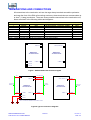
1
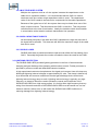
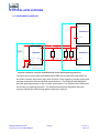
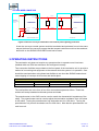
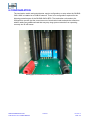
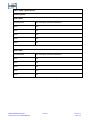
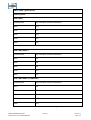
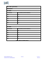
Title
SILBUS
TERMINATION UNIT
TYPE SILBUS-OAS1
USER'S MANUAL
Document Number
120-339-12
Issue
02
1 OF 21
REVISION CONTROL
02
Add settings table
2012.08.20
JY
JY
CG
01
Original
2010.01.18
PB’
PB’
JY
Issue
Details
Date
Written
Designed
Approved
Austdac Pty Ltd
Unit 1 / 4 Packard Avenue
Castle Hill NSW 2154
Australia
PO Box 6486
Baulkham Hills Business Centre
NSW 2153
Australia
Phone: + 61 2 8851 5000
Fax: + 61 2 9899 2490
Website: www.austdac.com.au
Austdac Inc.
455 Lowries Run Rd,
Pittsburgh, PA 15237
USA
Phone: +1 888 254 9155
Fax: +1 412 635 0179
Copyright 2010-01-18
This document remains the property of Austdac Pty. Ltd. It is subject to its recall and must not be
reproduced in part or whole or its contents divulged to third parties without prior written approval
from Austdac Pty Ltd.
SILBUS TERMINATION UNIT
TYPE SILBUS-OAS1 USER'S MANUAL
2 OF 21
120-339-12
Issue: 02
TABLE OF CONTENTS
REVISION CONTROL .................................................................................................................... 2
TABLE OF CONTENTS .................................................................................................................. 3
PHOTOGRAPHS ............................................................................................................................ 3
TABLES.......................................................................................................................................... 3
FIGURES........................................................................................................................................ 3
1 GENERAL DESCRIPTION .......................................................................................................... 4
2 FRONT PANEL LAYOUT............................................................................................................. 4
3 THEORY OF OPERATION .......................................................................................................... 5
3.1 TRANSMISSION LINE .......................................................................................................... 5
3.2 PRACTICAL INSTALLATIONS ............................................................................................. 8
3.2.1 SHORT CABLE RUN ..................................................................................................... 8
3.2.2 LONG CABLE RUN........................................................................................................ 8
3.2.3 MULTIPLE WIRE SYSTEM ............................................................................................ 9
3.2.4 HIGH CAPACITANCE CABLES ..................................................................................... 9
3.2.5 SILBUS LOADS ............................................................................................................. 9
3.3 LIGHTNING PROTECTION .................................................................................................. 9
4 TYPICAL APPLICATIONS ......................................................................................................... 10
4.1 THREE-WIRE CONVEYOR ................................................................................................ 10
4.2 TWO-WIRE CONVEYOR.................................................................................................... 11
5 OPERATING INSTRUCTIONS .................................................................................................. 11
6 CONFIGURATION..................................................................................................................... 13
TERMINATIONS AND CONNECTIONS ....................................................................................... 20
6.1 EARTH CONNECTIONS..................................................................................................... 21
7 SPECIFICATIONS ..................................................................................................................... 21
PHOTOGRAPHS
Photograph 1 SILBUS-OAS1-XXX front panel layout...................................................................... 4
Photograph 2 Access to configuration switch and potentiometer..................................................... 5
Photograph 3 Termination switch and potentiometer .................................................................... 13
TABLES
Table 1 Test facility connection details.......................................................................................... 11
Table 2 DIP Switch Setting ........................................................................................................... 12
Table 3 CAC5 2 wire OAS1 Settings............................................................................................. 14
Table 4 CAC5 3 wire OAS1 Settings............................................................................................. 15
Table 5 CAC6 2 wire OAS1 Settings............................................................................................. 16
Table 6 CAC6 3 wire OAS1 Settings............................................................................................. 17
Table 7 CAC7 2 wire OAS1 Settings............................................................................................. 18
Table 8 CAC7 3 wire OAS1 Settings............................................................................................. 19
Table 9 Termination unit connection details .................................................................................. 20
FIGURES
Figure 1 Near end and far end waveforms with no termination (CAC7)........................................... 6
Figure 2 Near end and far end waveforms with termination (CAC7 and 150R + 100nF) ................. 7
Figure 3 Near end and far end waveforms with termination (CAC7 and 150R + 300nF) ................. 7
Figure 4 Near end waveform showing the effect of high capacitance on slew rate .......................... 8
Figure 5 Three-wire conveyor termination and control panel lightning protection .......................... 10
Figure 6 Two-wire conveyor termination and control panel lightning protection............................. 11
Figure 7 SILBUS-OAS1-XXX terminal diagram............................................................................. 20
Figure 8 Typical connection diagrams........................................................................................... 20
SILBUS TERMINATION UNIT
TYPE SILBUS-OAS1 USER'S MANUAL
3 OF 21
120-339-12
Issue: 02
1 GENERAL DESCRIPTION
The SILBUS termination unit type SILBUS-OAS1-XXX is an explosion protected DIN railmounting module that is used to provide a SILBUS network termination, SILBUS test points
and head-end lightning protection. Typically a termination unit is required at both ends of a
SILBUS network or transmission line to help stop reflections and ringing in the SILBUS
waveform. The SILBUS-OAS1-XXX is produced in two versions, the SILBUS-OAS1-BEG
for the head-end and the SILBUS-OAS1-END for the tail-end of the SILBUS network.
The SILBUS-OAS1-BEG provides network termination, test facilities as well as lightning
protection for head-end control panels while the SILBUS-OAS1-END only provides network
termination and test facilities.
The termination unit is housed within a DIN rail mounting enclosure measuring 45mm (W) x
75mm (H) x 110mm (D). The front panel is located between the two top of enclosure
mounted terminal blocks to provide easy access to the two test points.
2 FRONT PANEL LAYOUT
The termination front panel is located between the terminal blocks that form part of the
enclosure. The front panel has two 2mm test points spaced at 19mm that provide test
access to the SILBUS signal and common signals. The front panel is shown in photograph
1 below.
Photograph 1 SILBUS-OAS1-XXX front panel layout
SILBUS TERMINATION UNIT
TYPE SILBUS-OAS1 USER'S MANUAL
4 OF 21
120-339-12
Issue: 02
The front panel can be snapped out and removed by using a wide bladed flat screw driver
to gain access to the configuration potentiometer and switch. Photograph 2 below shows
the front panel removed and the location of the configuration potentiometer and switch.
The two test sockets are also shown.
Photograph 2 Access to configuration switch and potentiometer
3 THEORY OF OPERATION
SILBUS or Dupline® is an extremely reliable and noise tolerant system that is in most
cases tolerant of unterminated networks, but some installations due line length, branches
and system architecture require line termination to function reliably.
3.1 TRANSMISSION LINE
The SILBUS signal on a cable follows the principles of transmission line theory. If a
transmission line is not terminated correctly at its end points reflections can occur that will
cause ringing on the SILBUS waveform. This ringing can cause the channel generator to
misinterpret the channel pulse low period and falsely decide that a channel is on when it is
not. By correctly terminating the ends of a SILBUS network transmission line the ringing
can be eliminated or significantly reduced to a point where it will not cause any incorrect
operation of the SILBUS system.
SILBUS TERMINATION UNIT
TYPE SILBUS-OAS1 USER'S MANUAL
5 OF 21
120-339-12
Issue: 02
The waveform below shows both the near end and far end waveforms on an unterminated
cable. Strong reflections can be seen at both the falling edge and rising edge of the
waveform.
Figure 1 Near end and far end waveforms with no termination (CAC7)
If the cable is terminated in the correct impedance a significant improvement in the signal
quality can be seen. In the waveform below the same cable has been terminated with a
150ohms in series with 100nF. However as the GSW1 source impedance is lower than the
cable impedance some reflections are still evident.
SILBUS TERMINATION UNIT
TYPE SILBUS-OAS1 USER'S MANUAL
6 OF 21
120-339-12
Issue: 02
Figure 2 Near end and far end waveforms with termination (CAC7 and 150R + 100nF)
By adding capacitance to the line this forms a low pass filter which attenuates the reflection
due to the GSW1 source impedance mismatch. In the waveform below the same cable has
been terminated with a 150ohms in series with 300nF.
Figure 3 Near end and far end waveforms with termination (CAC7 and 150R + 300nF)
SILBUS TERMINATION UNIT
TYPE SILBUS-OAS1 USER'S MANUAL
7 OF 21
120-339-12
Issue: 02
The additional factor that must be taken into account is the overall delay of the SILBUS
signal. The delay is due to both the length of the cable and the slew rate of the signal. The
GSW1 Build 1 can tolerate a delay of 110us and the GSW1 Build 2 can tolerate a delay of
200us. While additional capacitance helps attenuate the reflection it can add delay due to
slew rate.
Figure 4 Near end waveform showing the effect of high capacitance on slew rate
3.2 PRACTICAL INSTALLATIONS
In practice the installations will vary considerable from the ideal situation. The following
describes the effect of various installations.
3.2.1 SHORT CABLE RUN
Short cable runs of less than 4km require good termination of the cable as the
unterminated cable will generate a strong reflection as there is in-sufficient cable
attenuation or capacitance to suppress the reflection.
In these cases the OAS1 is used to terminate the cable as well as adding
capacitance with the OAS1 to attenuate the driving end reflection.
3.2.2 LONG CABLE RUN
Long cable runs of 4km or more generally have less reflection issues as the
attenuation of the cable and added capacitance of the cable tends to suppress the
reflection. In many cases it may not be necessary to use an OAS1.
However it is still recommended that an OAS1 be used to terminate the cable
however a lower capacitance value in the OAS1 should be used to reduce the effect
on slew rate.
SILBUS TERMINATION UNIT
TYPE SILBUS-OAS1 USER'S MANUAL
8 OF 21
120-339-12
Issue: 02
3.2.3 MULTIPLE WIRE SYSTEM
Multiple wire systems such as a 3 wire system increase the capacitance on the
cable due to capacitive addition. It is recommended that the OAS1 is used to
terminate each wire unless a high capacitance cable is used. The capacitance
value of the OAS1 needs to be reduced to compensate for the cable capacitance.
Because of the typical use of a 3 wire system there may be times when one of the
wires is open circuited. This disconnects the OAS1 on that line. This may lead to
reflections due to the loss of termination. Ideally the isolation switch should switch
in a termination at the break to maintain transmission line operation.
3.2.4 HIGH CAPACITANCE CABLES
As discussed previously if the cable and OAS1 capacitance is high the slew rate of
the signal will be affected. This slew rate will affect the maximum length of the cable
that can be used.
3.2.5 SILBUS LOADS
SILBUS loads acts as partial termination loads and can affect the final setting of the
OAS1. Generally the greater the number of loads the lower the need for the OAS1.
3.3 LIGHTNING PROTECTION
The SILBUS-OAS1-BEG provides lightning protection in the form of semiconductor
clamping and gas discharge tube clamping with diversion to earth. Further protection is
provided by common mode and differential inductive isolation.
A high speed semiconductor clamp between the signal and common lines will clamp any
differential lightning induced voltages to approximately 22 volts. This clamp is backed up
by a differential and common mode three terminal gas discharge device that shunts
lightning induced energy away to earth. Lightning induced energy is typically very high
frequency so inductive filters are used to isolate the control panel terminals of the
SILBUS-OAS1-BEG from high energy spikes. It is for this same high frequency that any
wiring from the earth terminals of the SILBUS-OAS1-BEG must be carried out in a low
inductive manner, failure to do so will render the SILBUS-OAS1-BEG ineffective in
reducing damage from lightning induced energy.
SILBUS TERMINATION UNIT
TYPE SILBUS-OAS1 USER'S MANUAL
9 OF 21
120-339-12
Issue: 02
4 TYPICAL APPLICATIONS
4.1 THREE-WIRE CONVEYOR
11 SIGNAL (MONITOR)
TERMINATION UNIT
TYPE SILBUS-OAS1-END
14 COMMON
1 SIGNAL
LANYARD
LANYARD8
MONITOR
MONITOR11
TO CHANNEL
GENERATOR
AND REMAINDER
OF PANEL
TERMINATION UNIT
TYPE SILBUS-OAS1-BEG
3 COMMON
SWITCH
TX
A?
11 SIGNAL (MONITOR)
EOL
TX
P7
EOL
TX
P8
TERMINATION UNIT
TYPE SILBUS-OAS1-END
COMMON
COMMON 14
14 COMMON
6 EARTH1
7 EARTH2
EARTH EARTH
HEAD-END CONTROL PANEL
TAIL-END UNIT
Figure 5 Three-wire conveyor termination and control panel lightning protection
The figure above shows how the SILBUS-OAS1-BEG and two SILBUS-OAS1-END can
be used to correctly terminate a three wire conveyor control system to prevent ringing and
resultant interference with the SILBUS signal waveform. The SILBUS-OAS1-BEG also
provides lightning protection to the conveyor control panel. The SILBUS-OAS1-END does
not provide any lightning protection. The individual transmitters distributed along the
conveyor should also be protected against lightning if required.
SILBUS TERMINATION UNIT
TYPE SILBUS-OAS1 USER'S MANUAL
10 OF 21
120-339-12
Issue: 02
4.2 TWO-WIRE CONVEYOR
1 SIGNAL
LANYARD8
MONITOR
MONITOR11
TO CHANNEL
GENERATOR
AND REMAINDER
OF PANEL
TERMINATION UNIT
TYPE SILBUS-OAS1-BEG
3 COMMON
SWITCH
TX
A?
11 SIGNAL (MONITOR)
EOL
TX
P7
TERMINATION UNIT
TYPE SILBUS-OAS1-END
COMMON
COMMON 14
14 COMMON
6 EARTH1
7 EARTH2
EARTH EARTH
HEAD-END CONTROL PANEL
TAIL-END UNIT
Figure 6 Two-wire conveyor termination and control panel lightning protection
A two wire conveyor control system would be terminated and protected in much the same
way as the three wire conveyor except that the lanyard conductor would not be used and
terminal 8 on the SILBUS-OAS1-BEG would not be used.
5 OPERATING INSTRUCTIONS
The termination unit does not require any operator action to operate once it has been
installed within an IP54 host enclosure and configured correctly.
Test connection facilities are provided on the front panel of the termination unit to provide a
method of connecting test equipment to the network while the system is in operation. Care
should be exercised when using these test facilities to not short the SILBUS network and
cause tripping of conveyor drive motors and similar plant.
TERMINATION UNIT TEST FACILITY CONNECTIONS
FRONT PANEL NAME
COLOUR
NETWORK SIGNAL
SIG
RED
SIGNAL
COM
BLACK
COMMON
Table 1 Test facility connection details
TERMINAL No.
11
14
The test facilities are in the form of two 2mm test sockets spaced at 19mm. These test
sockets will accept standard multimeter probes and leads.
The potentiometer in the OAS1 can be used to match the characteristic impedance of the
cable. The potentiometer can be used to adjust the termination resistance from 100 ohms
to 600 ohms. Turning the potentiometer fully clockwise sets it to 100 ohms. Turning the
potentiometer fully counter clockwise sets it to 600 ohms. Note that the potentiometer is a
multi-turn unit.
SILBUS TERMINATION UNIT
TYPE SILBUS-OAS1 USER'S MANUAL
11 OF 21
120-339-12
Issue: 02
The DIP switch settings are as follows;
Switch
Function
1
Turns ON the termination circuits
2
Sets capacitance to 47nF
3
Sets capacitance to 100nF
4
Sets capacitance to 220nF
5
Sets capacitance to 330nF
Combinations of switch 2 to 5 can be used for higher capacitance.
Table 2 DIP Switch Setting
SILBUS TERMINATION UNIT
TYPE SILBUS-OAS1 USER'S MANUAL
12 OF 21
120-339-12
Issue: 02
6 CONFIGURATION
The termination switch and potentiometer require configuration or setup when the SILBUSOAS1-XXX is installed on a SILBUS network. There is no configuration required for the
lightning protection part of the SILBUS-OAS1-BEG. The termination unit needs to be
configured to provide just the correct amount of termination load to absorb the reflections
without adding any additional load that may stop long system networks from operating
correctly due to IxR losses.
Photograph 3 Termination switch and potentiometer
SILBUS TERMINATION UNIT
TYPE SILBUS-OAS1 USER'S MANUAL
13 OF 21
120-339-12
Issue: 02
CAC5 Cable Typical Setup
2 Wire System
OAS1-BEG
Potentiometer
fully clockwise (minimal resistance)
SW1
OFF
SW2
OFF
SW3
OFF
SW4
OFF
SW5
OFF
OAS1-END
Potentiometer
fully clockwise (minimal resistance)
SW1
ON
SW2
ON
SW3
ON
SW4
OFF
SW5
OFF
Table 3 CAC5 2 wire OAS1 Settings
SILBUS TERMINATION UNIT
TYPE SILBUS-OAS1 USER'S MANUAL
14 OF 21
120-339-12
Issue: 02
CAC5 Cable Typical Setup
3 Wire System
OAS1-BEG
Potentiometer
fully clockwise (minimal resistance)
SW1
OFF
SW2
OFF
SW3
OFF
SW4
OFF
SW5
OFF
OAS1-END WIRE 1
Potentiometer
fully clockwise (minimal resistance)
SW1
ON
SW2
ON
SW3
ON
SW4
OFF
SW5
OFF
OAS1-END WIRE 2 (LANYARD)
Potentiometer
fully clockwise (minimal resistance)
SW1
ON
SW2
ON
SW3
ON
SW4
OFF
SW5
OFF
Table 4 CAC5 3 wire OAS1 Settings
SILBUS TERMINATION UNIT
TYPE SILBUS-OAS1 USER'S MANUAL
15 OF 21
120-339-12
Issue: 02
CAC6 Cable Typical Setup
2 Wire System
OAS1-BEG
Potentiometer
fully clockwise (minimal resistance)
SW1
OFF
SW2
OFF
SW3
OFF
SW4
OFF
SW5
OFF
OAS1-END
Potentiometer
fully clockwise (minimal resistance)
SW1
ON
SW2
ON
SW3
ON
SW4
OFF
SW5
OFF
Table 5 CAC6 2 wire OAS1 Settings
SILBUS TERMINATION UNIT
TYPE SILBUS-OAS1 USER'S MANUAL
16 OF 21
120-339-12
Issue: 02
CAC6 Cable Typical Setup
3 Wire System
OAS1-BEG
Potentiometer
fully clockwise (minimal resistance)
SW1
OFF
SW2
OFF
SW3
OFF
SW4
OFF
SW5
OFF
OAS1-END WIRE 1
Potentiometer
fully clockwise (minimal resistance)
SW1
ON
SW2
ON
SW3
ON
SW4
OFF
SW5
OFF
OAS1-END WIRE 2 (LANYARD)
Potentiometer
fully clockwise (minimal resistance)
SW1
OFF
SW2
ON
SW3
ON
SW4
OFF
SW5
OFF
Table 6 CAC6 3 wire OAS1 Settings
SILBUS TERMINATION UNIT
TYPE SILBUS-OAS1 USER'S MANUAL
17 OF 21
120-339-12
Issue: 02
CAC7 Cable Typical Setup
2 Wire System
OAS1-BEG
Potentiometer
fully clockwise (minimal resistance)
SW1
OFF
SW2
OFF
SW3
OFF
SW4
OFF
SW5
OFF
OAS1-END
Potentiometer
fully clockwise (minimal resistance)
SW1
ON
SW2
OFF
SW3
OFF
SW4
ON
SW5
OFF
Table 7 CAC7 2 wire OAS1 Settings
SILBUS TERMINATION UNIT
TYPE SILBUS-OAS1 USER'S MANUAL
18 OF 21
120-339-12
Issue: 02
CAC7 Cable Typical Setup
3 Wire System
OAS1-BEG
Potentiometer
fully clockwise (minimal resistance)
SW1
OFF
SW2
OFF
SW3
OFF
SW4
OFF
SW5
OFF
OAS1-END WIRE 1
Potentiometer
fully clockwise (minimal resistance)
SW1
ON
SW2
OFF
SW3
OFF
SW4
ON
SW5
OFF
OAS1-END WIRE 2 (LANYARD)
Potentiometer
fully clockwise (minimal resistance)
SW1
OFF
SW2
OFF
SW3
OFF
SW4
ON
SW5
OFF
Table 8 CAC7 3 wire OAS1 Settings
SILBUS TERMINATION UNIT
TYPE SILBUS-OAS1 USER'S MANUAL
19 OF 21
120-339-12
Issue: 02
TERMINATIONS AND CONNECTIONS
All connections to the termination unit are via cage-clamp terminals around the perimeter
and near the front of the DIN rail mounting enclosure, these terminals can accommodate up
to 4mm2 (11awg) conductors. There are seven possible connections to the termination unit;
these are shown in the following tables and diagrams:
TERMINAL #
1
3
6
7
8
11
14
NAME
SIGNAL
COMMON
EARTH
EARTH
LANYARD
MONITOR
COMMON
TERMINATION UNIT CONNECTION DETAILS
WIRE COLOUR
FUNCTION
RED
SILBUS SIGNAL CONTROL PANEL
BLACK
SILBUS COMMON CONTROL PANEL
GREEN/YELLOW
PROTECTIVE EARTH
GREEN/YELLOW
PROTECTIVE EARTH
YELLOW
RED
BLACK
-BEG / -END
-BEG
-BEG
-BEG
-BEG
1
-BEG
-BEG -END
-BEG -END
NOTE 1 - FITTED TO SILBUS-OAS1-END BUT NOT USED IN TAIL END APPLICATIONS
Table 9 Termination unit connection details
1 SIGNAL
LANYARD 8
SIGNAL (MONITOR) 11
MONITOR 11
TERMINATION UNIT
TYPE SILBUS-OAS1-BEG
3 COMMON
TERMINATION UNIT
TYPE SILBUS-OAS1-END
COMMON 14
COMMON 14
6 EARTH1
7 EARTH2
Figure 7 SILBUS-OAS1-XXX terminal diagram
SIG
1 SIGNAL
LANYARD 8
MONITOR 11
TO CHANNEL
GENERATOR
LANYARD (NOTE1)
MONITOR (SIGNAL)
TO FIELD
NETWORK
TERMINATION UNIT
TYPE SILBUS-OAS1-BEG
COM
3 COMMON
COMMON 14
SIGNAL (MONITOR) 11
SIGNAL
FROM FIELD
NETWORK
TERMINATION UNIT
TYPE SILBUS-OAS1-END
COMMON
COMMON 14
COMMON
6 EARTH1
7 EARTH2
NOTE 1 LANYARD ONLY REQUIRED IN THREE WIRE SYSTEMS
EARTH
EARTH
Figure 8 Typical connection diagrams
SILBUS TERMINATION UNIT
TYPE SILBUS-OAS1 USER'S MANUAL
20 OF 21
120-339-12
Issue: 02
6.1 EARTH CONNECTIONS
The SILBUS-OAS1-BEG has two earth connection terminals (6, 7), these terminals must
be connected independently to a low impedance lightning earth point using a minimum of
4mm2 conductors. These conductors shall be as short as possible and twists and bends
should be avoided if proper lightning protection is to be afforded.
The two earth conductors should be segregated from all other panel wiring to reduce any
induction of lightning derived energy into signal conductors within the control panel.
If the lightning earth point is far away from the control panel then an earth stud or terminal
shall be provided on the control panel gear tray to allow the earth conductors to be
increased to 8mm2.
7 SPECIFICATIONS
Name ..............................................................................................................Termination unit
Type..................................................................SILBUS-OAS1-BEG and SILBUS-OAS1-END
Terminations ................................................................. Cage clamp 4mm2 (11awg) maximum
Size.................................................................................45mm (W) x 75mm (H) x 110mm (D)
Mass ................................................................................................................................ 145g
Fixing ......................................... TS35 DIN rail or screw mount M4 on 85mm x 61mm centres
Ingress protection .............................................................................................................IP20
Enclosure material ............................................................ Polycarbonate (30%GV) UL 94 V-1
Enclosure colour ..............................................................................................RAL 7032 Grey
Terminal material ..............................................................................Polycarbonate UL 94 V-2
Terminal block colour...................................................................................................... Black
Operating temperature range.................................................................................0ºC to 40ºC
Storage temperature range ................................................................................ -20ºC to 80ºC
Operating relative humidity range ...............................................10% to 90% Non condensing
Maximum clamping voltage (-BEG only) ............................................................................22V
Maximum impulse current 8/20uS (-BEG only) .................................................................. 5kA
SILBUS TERMINATION UNIT
TYPE SILBUS-OAS1 USER'S MANUAL
21 OF 21
120-339-12
Issue: 02