1
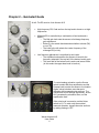
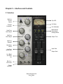
WAVES
Kramer HLS Channel
User Guide
TABLE OF CONTENTS
CHAPTER 1 – INTRODUCTION ..............................................................................................................3
1.1 WELCOME .........................................................................................................................................3
1.2 ABOUT KRAMER HLS CHANNEL .........................................................................................................3
1.3 ABOUT THE MODELING ......................................................................................................................4
1.4 COMPONENTS ...................................................................................................................................5
CHAPTER 2 – QUICKSTART GUIDE......................................................................................................6
CHAPTER 3 – INTERFACE AND CONTROLS .......................................................................................7
3.1 INTERFACE ........................................................................................................................................7
3.2 CONTROLS ........................................................................................................................................8
CHAPTER 4 – THE WAVESYSTEM......................................................................................................14
4.1 THE WAVESYSTEM TOOLBAR ..........................................................................................................14
4.2 PRESET HANDLING ..........................................................................................................................14
4.3 INTERFACE CONTROLS ....................................................................................................................16
Waves Kramer HLS
User Guide
2
Chapter 1 – Introduction
1.1 Welcome
Thank you for choosing Waves! In order to get the most out of your Waves processor, please take the
time to read through this manual.
In conjunction, we also suggest that you become familiar with www.wavesupport.net. There you will find
an extensive Answer Base, the latest Tech Specs, detailed Installation guides, new Software
Updates, and current information on Authorization and Registration.
By signing up at www.wavesupport.net, you will receive personalized information on your registered
products, reminders when updates are available, and information on your authorization status.
1.2 About Kramer HLS Channel
The HLS Channel is modeled after the legendary Helios console channels, designed and built by Richard
Swettenham, and used by Eddie Kramer during the late ’60s to record some of rock’s most classic tracks
at London’s Olympic Studios. During the early ’60s, Swettenham worked at EMI’s Abbey Road Studios as
a service/design engineer, later moving to Olympic studios, where he was asked to design and build an
especially “musical” recording desk. The desk was a success, and began a golden era for Olympic
studios, which hosted recording sessions for such artists as Jimi Hendrix, Rolling Stones, Led Zeppelin,
Traffic and many others.
Following the success of the first Olympic desk came its successor. Both desks had silver-faced panels
with 3-band EQs that had variable boost or cut for midrange frequencies, a high shelf at 10 kHz, and a
special low filter that could boost at frequencies of 60Hz – 400Hz and cut at 50Hz. Their mic preamps
used an especially musical transformer made by Lustraphone, a London-based consumer and pro audio
equipment manufacturer.
This success of these designs drew special interest from Chris Blackwell, founder of Island Records, who
wanted to base a new studio venture on Swettenham’s console designs. In order to avoid conflict with
Olympic, rather than commissioning Richard Swettenham to build a console, Blackwell funded
Swettenham’s going into business for himself, under the brand name Helios. Under the Helios brand,
Swettenham continued to produce custom-made recording desks for various studios using Olympic-style
EQ’s, with Beyer transformers replacing Lustraphone’s and other small variations.
Swettenham’s channels shared many basic features, but were essentially custom-built to order, with
some user-driven changes. Since the original Olympic desks have since gone through several
restorations jobs and lost the original transformers, Waves called upon Eddie Kramer, the engineer at
Olympic during its heyday. Kramer helped us find the Helios channel that best characterized the sound of
the classic rock recordings we all know and love. Eventually, we chose the first desk revision from the
Rolling Stones mobile truck, courtesy of Mr. David Kean and the Audities Foundation. Thanks to them,
Waves Kramer HLS
User Guide
3
we were able to model original channels that were in the truck from 1970 – 1973, when the console was
redone by Helios according to specs from engineer Mick McKenna. Our long, arduous search for the
perfect Olympic-style channel reflects the rarity of the original units, and we are truly excited and proud to
present the Helios sound for posterity, and for the creative use of generations to come.
1.3 About the Modeling
Many different elements contribute to the unique sonic characteristics of analog gear such as the Helios
mixing console. Waves painstakingly modeled and incorporated these elements into the Kramer HLS
Channel, in order to fully capture and replicate the sound and performance of the original equipment. In
addition to modeling the Helios EQs, we also modeled the unique behavior, coloration, and drive of the
console’s preamps.
These are some of the most important elements of analog behavior:
•
Total Harmonic Distortion
Perhaps the most important analog behavior is Total Harmonic Distortion or THD, which is
defined as the ratio of the sum of the powers of all harmonic components to the power of the
fundamental frequency. THD is usually caused by amplification, and changes signal shape and
content by adding odd and even harmonics of the fundamental frequencies, which can change
the overall tonal balance. THD can also change peak output gain, usually by no more than
+/- 0.2-0.3 dB.
•
Transformers
Some hardware uses transformers to stabilize or change Input/Output loads and signal levels. In
earlier days, transformers did not have a flat frequency response, and often introduced low and
super-high frequency roll offs. The original channel has transformers which cause high-frequency
roll off, so if you encounter loss above 10 kHz, this is due to the modeled transformers.
•
Hum
Waves modeled both 50 Hz power current and 60 Hz power current. If you listen closely, you
will hear that there is a difference in hum level between 50 Hz and 60 Hz. Since hum is unique
to each region and dependent upon the local electrical conditions, you may find that the
modeled hum is different than the hum already present in your studio, and may not be suitable
for your particular use.
• Noise
All analog equipment generates internal noise or a noise floor. In vintage equipment, the noise
floor is sometimes quite high and colored. Waves modeled the noise to match the level and color
of noise exhibited by the original unit, both with and without signal present.
Waves Kramer HLS
User Guide
4
1.4 Components
WaveShell technology enables us to split Waves processors into smaller plug-ins, which we call
components. Having a choice of components for a particular processor gives you the flexibility to choose
the configuration best suited to your material.
The Kramer HLS has two component processors:
•
Kramer HLS Stereo – A 3-band stereo channel
•
Kramer HLS Mono – A 3- band mono channel
Latency
HLS latency differs for Native & TDM versions:
Native
161 samples (all supported sample rates)
TDM
292 samples @ 44.1/48 kHz
548 samples @ 88.2/96 kHz
Waves Kramer HLS
User Guide
5
Chapter 2 – Quickstart Guide
At left: The EQ section of the Kramer HLS.
•
High frequency EQ: Grab and turn the top knob to boost or cut high
frequencies.
•
Midrange EQ is controlled by a combination of two knobs and a
switch:
o The Mid gain knob sets the amount of midrange frequency
gain adjustment.
o Below it is the switch that determines whether to boost (PK)
or cut (TR).
o The knob to the left selects the center frequency of the
midrange EQ (in kHz).
•
Low frequency adjustment is controlled by two knobs:
o The top Bass knob specifies the amount of boost for the
frequency selected in the top half of the bottom knob’s scale.
o The lower half of the bottom knob’s scale cuts lows at 50Hz.
(In this mode, the upper bass knob is inactive.)
To control analog coloration, use the Source
switch to select Mic/Line amplification and the
Preamp knob to select the amount of coloration.
Higher values introduce more harmonic
distortion with increased noise and hum. The
overall level will not change significantly, as the
HLS recreates the coloration alone, not the
amplification itself.
If the noise level is excessive, set the Noise
switch to LO. To retain only the modeled
harmonic distortion, bypass the noise and hum
by setting Analog to OFF.
Waves Kramer HLS
User Guide
6
Chapter 3 – Interface and Controls
3.1 Interface
Mic/Line
Source
Select
Clip LED
VU Meter
Preamp
Coloration
VU Calibration
Meter Select
Noise Mode
Analog Switch
.
High Freq
Gain Adjust
Mid Freq
Gain Adjust
Output Trim
Mid Freq
Selector
Mid Mode
Select
Input Gain
Low Freq
Boost/Gain
Output Gain
Low Band
and 50Hz
Cut
EQ Cut =
EQ In/Out
Phase
Inversion
Waves Kramer HLS
User Guide
7
3.2 Controls
Source Select toggles between Mic and Line levels.
Range
Mic, Line
Default
Line
Preamp determines the amount of preamp coloration. Higher values introduce more harmonic
distortion with increased noise and hum. The overall level will not change significantly, as the HLS
recreates the coloration alone, not the amplification itself.
Range
20 – 70 (in 10 dB steps)
Default
20
Waves Kramer HLS
User Guide
8
High Frequency Gain controls high shelf gain at 10 kHz.
Range
-16 dB to +12 dB (-16, -12, -8, -4, 0, 4, 8, 12)
Default
0
Mid Gain sets the amount of gain applied to the midrange bell filter, according to the selected mode.
Range
0 to 15 (15 dB in 0.1 steps)
Default
0dB
Mid Frequency selects frequency for the midrange bell filter.
Range
700 Hz to 6 kHz (700, 1, 1.4, 2, 2.8, 3.5, 4.5, 6)
Default
2.8
Waves Kramer HLS
User Guide
9
Mid Mode selects between boost (PK) and cut (TR).
Range
PK (boost), TR (cut)
Default
PK
Low Band Freq/Cut From 60 to 400, this knob is used to select the boost frequency. From 3 to 15, it is
used to select the amount of attenuation (in dB) of the 50 Hz low shelf.
LF Selection (upper half)
0 (Off) to 400 (60, 120, 250, 400 Hz)
50 Hz Attenuation (lower half)
0 (Off) to 15 (-3, -6, -9, -12, -15 dB)
Default
0 (Off)
Low Band Boost sets the amount of boost (in dB) for the frequency selected using the Low Band
Freq/Cut control described above.
Range
0 to 15 (15 dB boost in 0.1 steps)
Default
0
Waves Kramer HLS
User Guide
10
EQ Cut turns the EQ on (in) and off (cut), while maintaining the analog and preamp characteristics.
Range
In/Cut
Default
In
Analog controls turns the analog noise and hum modeling on and off, and sets the pitch of the hum to
match either European or American currents. To retain only the modeled harmonic distortion, bypass
the noise and hum by setting Analog to Off.
Range
50 Hz, 60 Hz, On/Off
Default
60 Hz
Noise pads the modeled noise and hum by 20 dB. If the noise level is excessive, set the Noise switch to
Low.
Range
Original, Low
Default
Original
Waves Kramer HLS
User Guide
11
Meter toggles the meter display between input and output monitoring.
Clip LED lights up when levels exceed 0 dBFS. Click to reset.
VU Meter displays input or output level in dBVU. Please note: The HLS Stereo component meter
displays the sum of both channels. The same signal fed to both channels will show an increase of 6 dB. If
this is problematic, use the VU Calibration function to compensate.
Range
24 – 8 dB
Default
18 dB of headroom (0 dBVU = -18 dBFS.)
VU Calibrate controls the VU meter headroom calibration.
Please note: The VU Calibration control is represented by the little screw-head right below the VU
meter display. It does not have a visible label and, for most users, the 18 dB default headroom
should be the best choice. However, if you use outboard gear in your studio and your VU meters
are calibrated for 14 dB headroom, the HLS allows you to calibrate its VU meter as well.
Waves Kramer HLS
User Guide
12
Trim displays the maximum peak level of the output signal and its distance from 0 dBFS. Clicking on
the trim value button will reset it to 0, and apply the differential to the output trim (up to 12 dB at a time.)
Range
-12 – +12 dB
Default
0
Input controls the input level.
Output controls the output level.
Range
-18 dB to +18 dB (in 0.1dB steps)
Default
0 dB
Waves Kramer HLS
User Guide
13
Chapter 4 – The WaveSystem
4.1 The WaveSystem Toolbar
All Waves processors feature the WaveSystem toolbar which takes care of most administrative functions
you will encounter while working with your Waves software. The features of the WaveSystem toolbar are
the same on practically all Waves processors, so familiarity with its features will be helpful whichever
processor you are using.
Toolbar Functions
Undo
Redo
Setup A/B
Copy A->B
Load
Save
?
Undoes the last 32 actions.
Redoes the last 32 undone actions.
Toggles between two presets. This is useful for close comparison of different parameter
settings
Copies the current settings to the second preset register
Recalls presets from file
Saves presets in the Waves file formats
Opens the manual for the processor you are using
4.2 Preset Handling
Preset Types
Factory Presets are permanent presets in the Load menu. Factory presets cannot be over-written or
deleted. When applicable, different component plug-ins may have different factory presets.
User Presets are your favorite settings of the plug-in saved as a preset in the Load menu, under ‘User
Presets’. User Presets can be over-written and deleted.
Setup Files may contain more than one preset. For example, a single file can contain all the presets for a
session. When you open a Setup File, all its setups become part of your Load pop-up menu for fast
access. This can be particularly useful with multiple instances of a plug-in in a single session. By saving
all the settings you create into a single Setup File, they can all be quickly available for every instance of
that plug-in.
Waves Kramer HLS
User Guide
14
Loading Presets and Setups
Click-and-hold on the Load button to see the Load pop-up menu. The menu is divided into four sections.
If a section is not currently available it will not appear in the Load pop-up menu.
Open Preset File… Select to open any setup or preset file, whether from the Library or your own
creations.
‘Filename.xps’:
Displays any currently loaded Setup File and its presets.
Factory Presets:
Displays the default Factory Presets.
User Presets:
Displays any loaded User Presets.
Saving Presets and Setups
Click-and-hold on the Save button to see the Save pop-up menu. Four options are available. If an option
is not currently available it will be grayed out and inaccessible.
Select this to start a new Setup file. There are two prompts - first for
the setup filename, then for the preset name. You must provide a
name for both the setup file and the preset. Click OK (ENTER) to
complete the save. It is a good idea to create a folder in which to
save several setup files for a project.
Save ‘File Name’ – “Preset Name” Overwrites the settings of the loaded preset (whether a User Preset
or a preset from a Setup File) with the current settings. If a Setup
File is currently loaded, the name of the Setup File is displayed
followed by the name of the preset itself. If a User Preset is loaded,
its name is displayed.
Save to ‘File Name’ As…
Saves the current settings as a new preset into the Setup file that is
open (if one is not open, the option is grayed out). You will be
prompted to give the preset a name.
Put into Preset Menu As…
Save the current settings into a User Preset that will always be in
your Load menu (until deleted). You will be prompted to give this
preset a name. User Presets are stored in the plug-in’s preference
file.
Save to New File…
Waves Kramer HLS
User Guide
15
Deleting Presets
You may delete User Presets and presets within a Setup File. Factory Presets and Setup Library files
cannot be deleted or overwritten.
1. Hold the Command (Mac)/Control (PC) key down.
2. Click-and-hold the Load button to see the pop-up menu.
3. While still holding the Command/Control key, select the preset or setup to delete.
4. A confirmation box will appear, allowing you to cancel or ‘OK’ the deletion.
A/B Comparison and Copying
The Setup A/Setup B button may be clicked to compare two settings. If you load a preset in the Setup B
position, this will not affect the preset loaded into the Setup A position, and vice-versa.
If you want to slightly modify the settings in Setup A, you can copy them to Setup B by clicking on the
Copy to B button, then alter Setup A and compare with the original Setup B.
The name of the current setup will be shown in the title bar (on platforms which support it), and will switch
as you change from Setup A to Setup B.
Note: an asterisk will be added to the preset name when a change is made to the preset -
4.3 Interface Controls
Controls can be in one of three states:
•
•
•
Not Selected where the control is not the target of any user entry
Selected where the control is the target of mouse control entry only
Selected and Active where the control is the target for both mouse and keyboard entry
Toggle Buttons
Toggle buttons display the state of a control, and allow switching between two or more states. Singleclick to change the control’s state. Some toggle buttons have a text display which updates with the
current setting, and others (bypass, solo, or monitoring toggles) illuminate when the control is active.
Some processors have link buttons between a pair of toggle buttons, allowing click-and-drag adjustment
while retaining the offset between the controls.
Waves Kramer HLS
User Guide
16
Value Window Buttons
Value windows display the value of a control and allow click-and-drag adjustment, or direct control via
the keyboard.
•
•
•
Using the mouse, click-and-drag on the value window to adjust. Some value windows support
left/right, some up/down (as you hover over a button, arrows will appear to let you know which
direction of movement that button supports).
Using the arrow keys, click once with mouse to select the button, and then use up/down –
left/right (depending on the direction supported by that button) to move in the smallest incremental
steps across the button’s range (holding down the arrow keys will move faster through the range).
Using key entry, double click on the button to open the value window, and directly enter the
value from your keyboard. If you enter an out of range number, the button stays selected but
remains at the current setting (system beeps? If system sounds are on?)
Some processors have link buttons between a pair of value windows, allowing click-and-drag
adjustment while retaining the offset between the controls.
Sliders
Click on the slider itself or anywhere within the sliders track. The numerical value of the slider settings is
displayed in a hover window above the slider path.
Hover Box
Hovering boxes will appear and display the control value when hovering with the mouse over the control.
Multiple Selection of Controls
One of the most powerful features of the WaveSystem is the ability to select and adjust many controls at
the same time. Using the mouse, simply drag-select the desired group of button or graphic controls by
clicking and holding at a point outside the controls and forming a rectangle to include the controls you
wish to adjust. Alternatively, you can hold down Shift while clicking the mouse on any control you wish to
link. This second method is useful when you want to select two (or more) controls that are separated on
the GUI by other controls you do not wish to select.
Waves Kramer HLS
User Guide
17
TAB Functions
TAB moves the ‘selected’ status to the next control, with shift-TAB moving in the reverse direction.
Additionally, the Mac has an option-TAB function for ‘down’ movement and shift-option-TAB for ‘up’
movement where applicable.
If you have several Value Window Buttons selected, TAB functions will take you through the selected
controls only.
Waves Kramer HLS
User Guide
18