1
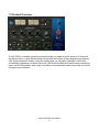
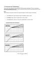
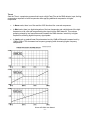
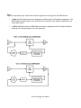
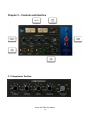
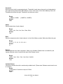
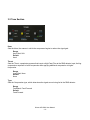
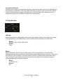
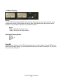
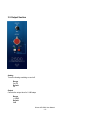
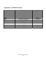
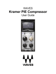
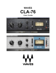
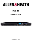
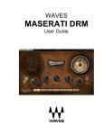
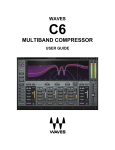
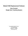
Waves API 2500
User Manual
TABLE OF CONTENTS
CHAPTER 1 – INTRODUCTION................................................................................................................................3
1.1 WELCOME...........................................................................................................................................................3
1.2 PRODUCT OVERVIEW ..........................................................................................................................................4
1.3 CONCEPTS AND TERMINOLOGY ............................................................................................................................5
1.4 COMPONENTS .....................................................................................................................................................8
CHAPTER 2 – QUICKSTART GUIDE .......................................................................................................................9
CHAPTER 3 – CONTROLS AND INTERFACE.......................................................................................................10
3.1 COMPRESSOR SECTION.....................................................................................................................................10
3.2 TONE SECTION .................................................................................................................................................12
3.3 LINK SECTION ...................................................................................................................................................13
3.4 METER DISPLAY ................................................................................................................................................14
3.5 OUTPUT SECTION..............................................................................................................................................15
CHAPTER 4 – THE WAVESYSTEM .......................................................................................................................17
4.1 THE WAVESYSTEM TOOLBAR ............................................................................................................................17
Toolbar Functions .............................................................................................................................................17
4.2 PRESET HANDLING ............................................................................................................................................17
Preset Types.....................................................................................................................................................17
Loading Presets and Setups ............................................................................................................................18
Saving Presets and Setups ..............................................................................................................................18
Deleting Presets ...............................................................................................................................................19
A/B Comparison and Copying ..........................................................................................................................19
4.3 INTERFACE CONTROLS ......................................................................................................................................19
Toggle Buttons..................................................................................................................................................19
Value Window Buttons......................................................................................................................................20
Sliders ...............................................................................................................................................................20
Hover Box .........................................................................................................................................................20
Multiple Selection of Controls ...........................................................................................................................20
TAB Functions ..................................................................................................................................................20
APPENDIX A – API 2500 CONTROLS ...................................................................................................................22
Waves API 2500 User Manual
-2-
Chapter 1 – Introduction
1.1 Welcome
Thank you for choosing Waves! In order to get the most out of your Waves processor, please take the
time to read through this manual.
In conjunction, we also suggest that you become familiar with www.wavesupport.net. There you will find
an extensive Answer Base, the latest Tech Specs, detailed Installation guides, new Software
Updates, and current information on Authorization and Registration.
By signing up at www.wavesupport.net, you will receive personalized information on your registered
products, reminders when updates are available, and information on your authorization status.
Waves API 2500 User Manual
-3-
1.2 Product Overview
The API 2500 is a versatile dynamics processor that lets you shape the punch and tone of mixes with
absolute accuracy. Its dual channel design lets the 2500 also function as two separate mono channels
via a single compression setting. Using auto-makeup gain, you can adjust Threshold or Ratio while
automatically maintaining a constant output level. With both Feed Back and Feed Forward compression
types, the API 2500 boasts a wide range of incredibly musical parameters which have made it a favorite
of engineers the world over.
Waves API 2500 User Manual
-4-
1.3 Concepts and Terminology
There are 3 main parameters that set the API 2500 from other compressors: Thrust, Compression
Type, and its adjustable Knee. When used in conjunction with one another, these parameters give the
API 2500 unprecedented flexibility.
Knee
Sets the knee, the manner in which the compressor begins to reduce the gain of the signal.
•
In the Hard position, gain reduction begins immediately at the set ratio.
•
In the Med position, there is a slight fade-in to the set ratio.
•
In the Soft position, there is an even more gradual fade-in to the set ratio.
Waves API 2500 User Manual
-5-
Thrust
Sets the Thrust, a proprietary process that inserts a High Pass Filter at the RMS detector input, limiting
compression response to lower frequencies while applying additional compression to higher
frequencies.
•
In Norm mode, there is no filter and the 2500 functions like a normal compressor.
•
In Med mode, there is a slight attenuation of the low frequencies and a slight boost of the high
frequencies, with a flat mid range affecting the signal into the RMS detector. This reduces
pumping caused by low frequencies and increases the RMS detectors’ sensitivity to higher
frequencies, affecting higher frequency signal peaks.
•
In Loud mode, a gradual linear filter attenuates level by 15dB at 20hz and increases level by
15dB at 20khz. This decreases low frequency pumping while increasing higher frequency
compression.
Waves API 2500 User Manual
-6-
Type
Sets the Compression type, which determines the signal source being fed to the RMS detector.
•
In New (Feed Forward) mode, the compressor works like newer VCA-based compressors. The
RMS detector sends a signal to the VCA that is an exact ratio of the desired compression, set
by the ratio control.
•
In Old (Feed Back) mode, the RMS detector receives a signal from the VCA output, and then
feeds the VCA a signal based on the set signal ratio.
Waves API 2500 User Manual
-7-
1.4 Components
WaveShell technology enables us to split Waves processors into smaller plug-ins, which we call
components. Having a choice of components for a particular processor gives you the flexibility to
choose a configuration suitable for your material.
The API 2500 has two component processors:
API 2500 Stereo – A stereo compressor that may also be used as two parallel mono processors.
API 2500 Mono – A mono compressor with an external sidechain option.
Waves API 2500 User Manual
-8-
Chapter 2 – Quickstart Guide
For those of you who are experienced users of audio signal processing tools, we recommend that you
approach the API 2500 as you would any compressor which you are already familiar. Keep in mind that
its Thrust, Compression Type, and Knee parameters offer capabilities that transcend other, more
conventional, processors.
Newer users should explore the API 2500’s preset library and use its presets as starting points for their
own experimentation. These presets also serve as a valuable introduction to compression techniques in
general, and offer a glimpse into the workflow of professional audio engineers.
We encourage all users to experiment with the API 2500’s settings in order to better understand its
unique processing power.
Waves API 2500 User Manual
-9-
Chapter 3 – Controls and Interface
3.1 Compressor Section
Waves API 2500 User Manual
- 10 -
Threshold
Sets the point at which compression begins. Threshold for each stereo channel is set independently,
since each channel has its own RMS detector, even in Link mode. In Auto Gain Make-up mode, the
Threshold also affects the gain. Threshold is a continuous control.
Range
+10dBu to -20dBu
Default
0dBu
(-12dBFS to -42dBFS)
Attack
Sets the attack time of each channel.
Range
.03ms, .1ms, .3ms, 1ms, 3ms, 10ms, 30ms
Default
1ms
Ratio
Sets the compression ratio of each channel. In Auto Gain Make-up mode, Ratio also affects the gain.
Range
1.5:1, 2:1, 3:1, 4:1, 6:1, 10:1, inf:1
Default
4:1
Release
Sets the Release time of the compressor. When set to Variable, Release time is controlled by the
Variable Release control, located to the right of the Release control.
Range
.05sec, .1sec, .2sec, .5sec, 1sec, 2sec, Variable
Default
.5sec
Variable Release
Controls the release time with a continuously variable knob . (Please note: Release control must be set
to Variable.)
Range
.05 seconds to 3 seconds in steps of 0.01ms
Default
.5sec
Waves API 2500 User Manual
- 11 -
3.2 Tone Section
Knee
Sets the Knee, the manner in which the compressor begins to reduce the signal gain.
Range
Hard, Med, Soft
Default
Hard
Thrust
Sets the Thrust, a proprietary process that inserts a High Pass Filter at the RMS detector input, limiting
compression response to lower frequencies while applying additional compression to higher
frequencies.
Range
Loud, Med, Norm
Default
Norm
Type
Sets the Compression type, which determines the signal source being fed to the RMS detector.
Range
Feed Back, Feed Forward
Default
Feed Forward
Waves API 2500 User Manual
- 12 -
A note about Sidechain:
Sidechain lets you trigger the compressor using an external source, which is fed into the RMS detector
and controls the compression of the input signal. Sidechain may only be used in New (Feed Forward)
mode. An external sidechain trigger cannot be used in Old (Feed Back) mode; attempting to do so
automatically switches the compressor to New (Feed Forward) mode.
3.3 Link Section
L/R Link
Sets the percentage of linkage between the left and right channels. While in Link mode, each channel
is still controlled by its own RMS detector, which prevents loading and slaving from either side.
Range
IND, 50%, 60%,70%,80%,90%,100%
Default
100%
Shape
Adjusts the Shape of the link control voltage mixing. The HP (high pass filter, LP low pass filter
eliminating the highs and a combination of both filters creating a band pass filter. the value of this circuit
allows the Link control voltage to not include certain frequencies. Different filter combinations can be
used, for example, to prevent percussive instruments on one channel from coupling and causing
unwanted compression on the other channel.
Range
HP, LP, BP, Off
Default
Off
Waves API 2500 User Manual
- 13 -
3.4 Meter Display
Meters
The API 2500’s Meters display dBFS. The Gain scale displays the amount of gain reduction during
compression with the 0 point located at the far the right, which allows higher gain reduction scale
resolution.. The API 2500 is capable of up to 30dB of reduction.
Range
0dB to -24dB (Gain Reduction mode)
-24dB to 0dB (Input and Output modes)
Switchable Display Modes
Range
GR, Out, In
Default
GR
Clip LED
Between the two Meters is a Clip LED which indicates input or output clipping. Since the LED shows
both input and output clipping, you must determine which of the two levels is excessive. The Clip LED
can be reset by clicking on it.
Waves API 2500 User Manual
- 14 -
3.5 Output Section
Analog
Turns the Analog modeling on and off.
Range
On/Off
Default
On
Output
Controls the output level in 0.1dB steps
Range
+/-24dB
Default
0dB
Waves API 2500 User Manual
- 15 -
Make-Up
Turns Auto Make-Up Gain on and off.
Range
Auto, Manual
Default
Auto
In
Acts as a master bypass for the entire compression chain. When set to Out, all compressor functions
are bypassed.
Range
In/Out
Default
In
Waves API 2500 User Manual
- 16 -
Chapter 4 – The WaveSystem
4.1 The WaveSystem Toolbar
All Waves processors feature the WaveSystem toolbar which takes care of most administrative
functions you will encounter while working with your Waves software. The features of the WaveSystem
toolbar are the same on practically all Waves processors, so familiarity with its features will be helpful
whichever processor you are using.
Toolbar Functions
Undo
Redo
Setup A/B
Copy A->B
Load
Save
?
Undoes the last 32 actions.
Redoes the last 32 undone actions.
Toggles between two presets. This is useful for close comparison of different parameter
settings
Copies the current settings to the second preset register
Recalls presets from file
Saves presets in the Waves file formats
Opens the manual for the processor you are using
4.2 Preset Handling
Preset Types
Factory Presets are permanent presets in the Load menu. Factory presets cannot be over-written or
deleted. When applicable, different component plug-ins may have different factory presets.
User Presets are your favorite settings of the plug-in saved as a preset in the Load menu, under ‘User
Presets’. User Presets can be over-written and deleted.
Setup Files may contain more than one preset. For example, a single file can contain all the presets for
a session. When you open a Setup File, all its setups become part of your Load pop-up menu for fast
access. This can be particularly useful with multiple instances of a plug-in in a single session. By saving
all the settings you create into a single Setup File, they can all be quickly available for every instance of
that plug-in.
Waves API 2500 User Manual
- 17 -
Loading Presets and Setups
Click-and-hold on the Load button to see the Load pop-up menu. The menu is divided into four
sections. If a section is not currently available it will not appear in the Load pop-up menu.
Open Preset File… Select to open any setup or preset file, whether from the Library or your own
creations.
‘Filename.xps’:
Displays any currently loaded Setup File and its presets.
Factory Presets:
Displays the default Factory Presets.
User Presets:
Displays any loaded User Presets.
Saving Presets and Setups
Click-and-hold on the Save button to see the Save pop-up menu. Four options are available. If an
option is not currently available it will be grayed out and inaccessible.
Save to New File…
Select this to start a new Setup file. There are two prompts - first
for the setup filename, then for the preset name. You must provide
a name for both the setup file and the preset. Click OK (ENTER)
to complete the save. It is a good idea to create a folder in which
to save several setup files for a project.
Save ‘File Name’ – “Preset Name” Overwrites the settings of the loaded preset (whether a User
Preset or a preset from a Setup File) with the current settings. If a
Setup File is currently loaded, the name of the Setup File is
displayed followed by the name of the preset itself. If a User
Preset is loaded, its name is displayed.
Save to ‘File Name’ As…
Saves the current settings as a new preset into the Setup file that
is open (if one is not open, the option is grayed out). You will be
prompted to give the preset a name.
Put into Preset Menu As…
Save the current settings into a User Preset that will always be in
your Load menu (until deleted). You will be prompted to give this
preset a name. User Presets are stored in the plug-in’s preference
file.
Waves API 2500 User Manual
- 18 -
Deleting Presets
You may delete User Presets and presets within a Setup File. Factory Presets and Setup Library files
cannot be deleted or overwritten.
1. Hold the Command (Mac)/Control (PC) key down.
2. Click-and-hold the Load button to see the pop-up menu.
3. While still holding the Command/Control key, select the preset or setup to delete.
4. A confirmation box will appear, allowing you to cancel or ‘OK’ the deletion.
A/B Comparison and Copying
The Setup A/Setup B button may be clicked to compare two settings. If you load a preset in the Setup B
position, this will not affect the preset loaded into the Setup A position, and vice-versa.
If you want to slightly modify the settings in Setup A, you can copy them to Setup B by clicking on the
Copy to B button, then alter Setup A and compare with the original Setup B.
The name of the current setup will be shown in the title bar (on platforms which support it), and will
switch as you change from Setup A to Setup B.
Note: an asterisk will be added to the preset name when a change is made to the preset -
4.3 Interface Controls
Controls can be in one of three states:
•
•
•
Not Selected where the control is not the target of any user entry
Selected where the control is the target of mouse control entry only
Selected and Active where the control is the target for both mouse and keyboard entry
Toggle Buttons
Toggle buttons display the state of a control, and allow switching between two or more states. Singleclick to change the control’s state. Some toggle buttons have a text display which updates with the
current setting, and others (bypass, solo, or monitoring toggles) illuminate when the control is active.
Some processors have link buttons between a pair of toggle buttons, allowing click-and-drag
adjustment while retaining the offset between the controls.
Waves API 2500 User Manual
- 19 -
Value Window Buttons
Value windows display the value of a control and allow click-and-drag adjustment, or direct control
via the keyboard.
•
•
•
Using the mouse, click-and-drag on the value window to adjust. Some value windows support
left/right, some up/down (as you hover over a button, arrows will appear to let you know which
direction of movement that button supports).
Using the arrow keys, click once with mouse to select the button, and then use up/down –
left/right (depending on the direction supported by that button) to move in the smallest
incremental steps across the button’s range (holding down the arrow keys will move faster
through the range).
Using key entry, double click on the button to open the value window, and directly enter the
value from your keyboard. If you enter an out of range number, the button stays selected but
remains at the current setting (system beeps? If system sounds are on?)
Some processors have link buttons between a pair of value windows, allowing click-and-drag
adjustment while retaining the offset between the controls.
Sliders
Click on the slider itself or anywhere within the sliders track. The numerical value of the slider settings
is displayed in a hover window above the slider path.
Hover Box
Hovering boxes will appear and display the control value when hovering with the mouse over the
control.
Multiple Selection of Controls
One of the most powerful features of the WaveSystem is the ability to select and adjust many controls
at the same time. Using the mouse, simply drag-select the desired group of button or graphic controls
by clicking and holding at a point outside the controls and forming a rectangle to include the controls
you wish to adjust. Alternatively, you can hold down Shift while clicking the mouse on any control you
wish to link. This second method is useful when you want to select two (or more) controls that are
separated on the GUI by other controls you do not wish to select.
TAB Functions
TAB moves the ‘selected’ status to the next control, with shift-TAB moving in the reverse direction.
Waves API 2500 User Manual
- 20 -
Additionally, the Mac has an option-TAB function for ‘down’ movement and shift-option-TAB for ‘up’
movement where applicable.
If you have several Value Window Buttons selected, TAB functions will take you through the selected
controls only.
Waves API 2500 User Manual
- 21 -
Appendix A – API 2500 Controls
Control
Threshold
Attack
Ratio
Release
Release Variable
Knee
Thrust
Type
L/R Link
Link Filter
Make-up
Meter
Analog
In
Output
Range
FeedBack, Feed forwards
IND, 50%,60%,70%,80%,90%,100%
Off, HP, LP, BP
Auto, Manual
GR, OUT, IN
Default
0dBu
1ms
4:1
.5sec
.5sec
Hard
Norm
Feed Forwards
100%
Off
Auto
GR
On/Off
In/Out
+/-24dB
0deg
In
0dB
+10dBu to -20dBu
.03ms, .1ms, .3ms, 1ms, 3ms, 10ms, 30ms
1.5:1, 2:1, 3:1 4:1 6:1 10:1 inf:1
.05sec, .1sec, .2sec, .5sec, 1sec, 2sec, Var
.05 to3sec in steps of 0.01ms
Hard, Med, Soft
Loud, Med, Norm
Waves API 2500 User Manual
- 22 -