1
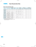
Basic Characteristics Data
Basic Characteristics Data
Switching
frequency
[kHz]
(reference)
Inrush
current
protection
Material
Flyback converter
445-495
*1
-
STMGF30 Forward converter
380-460
*1
-
STMGF15
Circuit method
*1 Refer to Specification.
*2 Refer to the Instruction Manual.
*3 MG series with the power supply unit, please refer to the basic characteristics of the MG series data.
STMG
STMG-12
Series/Parailel
operation
PCB/Pattern *3
Input
current
[A]
Model
Single
sided
Double
sided
Series
operation
Parailel
operation
glass fabric base,epoxy resin
Yes
*2
glass fabric base,epoxy resin
Yes
*2
DC-DC Converters Value-added type Instruction Manual
1
Function
STMG-14
1.1
Input Voltage Range
STMG-14
1.2
Overcurrent Protection
STMG-14
1.3
Overvoltage Protection
STMG-14
1.4
Isolation
STMG-14
1.5
Output Voltage Adjustment Range
STMG-14
1.6
Remote ON/OFF
STMG-14
1.7
Output ripple and ripple noise
STMG-14
2
Wiring Input terminal
STMG-15
3
Input Voltage/Current Range
STMG-15
4
Series/Parallel Operation
STMG-15
5
4.1
Series Operation
STMG-15
4.2
Parallel Operation
STMG-15
Assembling and Installation
STMG-16
5.1
Installation
STMG-16
5.2
STMGF15 Derating Curve
STMG-16
5.3
STMGF30 Derating Curve
STMG-17
5.4
Warranty
STMG-18
6
Note to use ±5V output
STMG-18
7
Options
STMG-18
7.1
Outline of Options
STMG-18
STMG-13
STMG
Instruction Manual
DC-DC Converters Value-added type
1 Functions
1.1 Input Voltage Range
1.6 Remote ON/OFF
¡The remote ON/OFF function is incorporated in the input circuit
and operated with RC(+) and RC(-). If positive logic control is required, order the power supply with “-R” option.
Table 1.1 Remote ON/OFF Specifications
¡If output voltage value doesn’t fall within specifications, a unit may
not operate in accordance with specifications and/or fail.
1.2 Overcurrent Protection
¡Overcurrent Operation
An overcurrent protection circuit is built-in and activated at 105%
of the rated current or above. It prevents the unit from short circuit
and overcurrent for less than 20 seconds. The output voltage of
the power supply will recover automatically if the fault causing
over current is corrected.
ON/OFF
logic
Standard
Negative
Optional
-R
Positive
Between RC(+) and RC(-) Output voltage
L level (0 - 1.2V) or short
H level (3 - 12V) or open
L level (0 - 1.2V) or short
H level (3 - 12V) or open
ON
OFF
OFF
ON
¡When RC is at low level, a current of 1mA typ will flow out.
RC(-) terminal is connected to the -VIN internally.
¡A short piece for remote ON/OFF function is installed on CN4
when power supply is shipped from factory.
When the output voltage drops after OCP works, the power supply
Please remove the short piece on CN4 to enable remote ON/OFF
enters a “hiccup mode” where it repeatedly turns on and off at a
function (Option -R does not come with the short piece).
certain frequency.
Vcc
1.3 Overvoltage Protection (Excluding STMGF15)
¡Over Voltage Protection (OVP) is built in. When OVP works, output voltage can be recovered by shutting down DC input for at
least one second or by turning off the remote control switch for
RC(+)
RC(+)
RC(-)
RC(-)
Transistor
Opto coupler
one second without shutting down the DC input. The recovery
time varies according to input voltage and input capacitance.
STMG
RC(+)
RC(+)
RC(-)
RC(-)
Remarks :
Note that devices inside the power supply may fail when a voltage
greater than the rated output voltage is applied from an external
Relay
IC
power supply to the output terminal of the power supply. This
could happen in in-coming inspections that include OVP function
test or when voltage is applied from the load circuit.
1.4 Isolation
¡When you run a Hi-Pot test as receiving inspection, gradually
increase the voltage to start. When you shut down, decrease the
voltage gradually by using a dial. Please avoid a Hi-Pot tester with
Fig1.1 Rc Connection Example
1.7 Output ripple and ripple noise
¡The specified ripple and ripple noise are measured by the method
introduced in Fig 1.2.
a timer because, when the timer is turned ON or OFF, it may gen-
+Vout
erate a voltage a few times higher than the applied voltage.
Load
1.5 Output Voltage Adjustment
-Vout
¡To increase an output voltage, turn a built-in potentiometer clockwise. To decrease the output voltage, turn it counterclockwise.
¡We are offering an Option -V, which doesn’t have a built-in potentiometer but instead enables you to adjust the output voltage by
using an external potentiometer (please see 7 Options).
Oscilloscope
BW : 100MHz
R
Coaxial Cable
C
Fig1.2 Method of Measuring Output Ripple and Ripple Noise
STMG-14
Instruction Manual
DC-DC Converters Value-added type
e
sN
o
i
4 Series/Parallel
Operation
2 Wiring Input terminal
¡If the power supply is to be turned ON/OFF directly with a switch,
inductance from the input line will induce a surge voltage several
times that of the input voltage and it may damage the power supply.
Make sure that the surge is absorbed, for example, by connecting
an electrolytic capacitor between the input terminals.
¡If an external filter containing L (inductance) is added to the input
line or a wire from the input source to the STMG series is long, not
4.1 Series Operation
¡You can use the power supplies in series operation by wiring as
shown below. In the case of (a) below, the output current should
be lower than the rated current for each power supply with the
only the reflected input noise becomes large, but also the output
lowest rated current among power supplies that are serially con-
of the converter may become unstable. In such case, connecting
nected. Please make sure that no current exceeding the rated
Ci to the input terminal is recommended.
¡If you use an aluminum electrolytic capacitor, please pay attention
current flows into a power supply.
(a)
to the ripple current rating.
L
+Vin
+
Load
Input
Power
Supply
Ci
-Vin
Power +
Supply Fig.2.1 Connecting an External Capacitor to the Input Side
If there is a possibility that a reverse polarity voltage is applied,
(b)
Power
Supply
connect a protection circuit externally as described below.
Fuse
-
+Vin
Schottky Barrier
Diode
-Vin
STMG
Load
Input
+
Load
¡If a reverse polarity voltage is applied to the input pin, the power
supply will fail.
Power +
Supply -
Fig.2.2 Connecting a Reverse Voltage Protection Circuit
Fig.4.1 Series Operation
3 Input Voltage/
Current Range
4.2 Parallel Operation
¡Parallel operation is not possible.
¡You can use the power supplies in redundancy operation by wiring
as shown below.
do not exceed the input voltage range shown in specifications.
I1
Power
Supply
+
Power
Supply
+
-
¡Please select an input power source with enough capacity, taking
into consideration of the start-up current (Ip), which flows when a
DC-DC converter starts up.
Input Voltage Range
I3
Load
¡If you use a non-regulated power source for input, please check
and make sure that its voltage fluctuation range and ripple voltage
I2
-
Input Current [A]
Fig.4.2 Redundancy Operation
Ip
¡Even a slight difference in output voltage can affect the balance
between the values of I1 and I2.
Please make sure that the value of I3 does not exceed the rated
current for each power supply.
Input Voltage [V]
I3 [ Rated Current Value
Fig.3.1 Input Current Characteristics
STMG-15
DC-DC Converters Value-added type
5 Assembling and Installation
100
Load factor [%]
5.1 Installation
¡Derating curve varies depending on the mounting direction.
Refer to 5.2 (STMGF15) ,Refer to 5.3 (STMGF30).
75
(C)
0
20
40
60
70
80
Ambient temperature Ta [C]
TB1
(Input)
Natural Convection
Mounting Method A-E
50
0
-20
(B)
(A)
Instruction Manual
(1) Standard type (No Case cover type)
TB1
(Input)
TB1
100
Load factor [%]
(Input)
Normal mounting
(D)
(E)
TB1
75
Natural Convection
Mounting Method A-E
50
(Input)
0
-20
TB1
0
20
40
50
60
80
Ambient temperature Ta [C]
(Input)
(2) Case cover type
Fig.5.3 STMGF15 Derating Curve for Convection Cooling
Fig.5.1 Mounting direction
(2) In the case of Forced Air Cooling
¡Please note that a power supply and chassis will become hot depending on mounting direction or operating condition.
¡In case of metal chassis, keep the distance between d1 for to insulate between lead of component and metal chassis.
If it is less than d1, insert the insulation sheet between power supply and metal chassis.
d1
STMG
¡In case of forced air cooling, please have sufficient ventilation to
keep the temperature of point A in Fig.5.4 at 105C or below.
Please also make sure that the ambient temperature does not exceed the range shown in Figure 5.5.
*Specifications for ripple and ripple noise changese in the shaded
area.
Point A
(A center point of DC-DC
converter case.)
d1=4mm min.
Fig.5.2 Mounting Method
5.2 STMGF15 Derating Curve
(1) In the case of Convection Cooling
¡If you derate the output current, you can use the unit in the temperature range from -20C to the maximum temperature shown
below.
*Specifications for ripple and ripple noise changese in the shaded
area.
STMG-16
Fig.5.4 STMGF15 Temperature Measuring Point
DC-DC Converters Value-added type
Instruction Manual
(2) In the case of Forced Air Cooling
100
Load factor [%]
¡In case of forced air cooling, please have sufficient ventilation to
keep the temperature of point A in Fig.5.7 at 110C or below.
Forced air
(0.5m3/min)
50
Please also make sure that the ambient temperature does not exceed the range shown in Figure 5.8.
*Specifications for ripple and ripple noise changese in the shaded
area.
0
-20
0
20
40
60
70
80
Point A
Ambient temperature Ta [C]
(A center point of DC-DC
converter case.)
(1) Standard type (No Case cover type)
Load factor [%]
100
75
Forced air
(0.5m3/min)
50
Fig.5.7 STMGF30 Temperature Measuring Point
0
-20
0
20
40
50
60
80
Ambient temperature Ta [C]
Fig.5.5 STMGF15 Derating Curve for Forced Air Cooling
5.3 STMGF30 Derating Curve
Load factor [%]
100
(2) Case cover type
Forced air
(0.5m3/min)
50
(1) In the case of Convection Cooling
¡If you derate the output current, you can use the unit in the temperature range from -20C to the maximum temperature shown
0
-20
below.
60
70
80
STMG
(1) Standard type (No Case cover type)
C B,D
A
75
D
50
Load factor [%]
Load factor [%]
40
E
A
E
100
75
Forced air
(0.5m3/min)
50
25
25
0
-20
0
20
40
60
70
80
(1) Standard type (No Case cover type)
C B,D
0
-20
0
20
25
30
35
40
60
70
80
Ambient temperature Ta [C]
Ambient temperature Ta [C]
Load factor [%]
20
Ambient temperature Ta [C]
*Specifications for ripple and ripple noise changese in the shaded
area.
B,C
0
E
(2) Case cover type
Fig.5.8 STMGF30 Derating Curve for Forced Air Cooling
A
75
50
25
0
-20
0
20
25
30
35
40
60
70
80
Ambient temperature Ta [C]
(2) Case cover type
Fig.5.6 STMGF30 Derating Curve for Convection Cooling
STMG-17
DC-DC Converters Value-added type
5.4 Warranty
Table 5.1 Warranty STMGF15 Standard type (No Case cover type)
Mounting
Cooling
Average ambient
Method
Method
temperature (year)
A-E
A-E
Convection
Forced air
Instruction Manual
6 Note to use ±5V output
Warranty
Io[75%
75%<Io[100%
Ta = 50C or less
5years
5years
Ta = 60C
5years
3years
Ta = 60C or less
5years
5years
Ta = 70C
3years
3years
¡If an output current is 0% to 5% of the rated current, the output is
influenced by the other output load condition.
20% output voltage fluctuation may occer.
To avoid the fluctuation, external bleeding resister is required to
draw sufficient current.
Table 5.2 Warranty STMGF15 Case cover type
Mounting
Method
A-E
Cooling
Average ambient
Method
temperature (year)
Convection Ta = 40C or less
Forced air
Ta = 50C
Warranty
+Vin
Io[75%
75%<Io[100%
5years
5years
5years
3years
Mounting
Cooling
Method
Method
A
B, C, D
E
A-E
Convection
Convection
Convection
Forced air
Average ambient
Warranty
Io[75%
75%<Io[100%
Ta = 50C or less
5years
5years
Ta = 60C
3years
3years
Ta = 30C or less
5years
5years
temperature (year)
Ta = 40C
5years
3years
Ta = 40C or less
5years
5years
Ta = 50C
5years
3years
Ta = 60C or less
5years
5years
Ta = 70C
3years
3years
Mounting
Method
A
B, D
C
E
Cooling
Average ambient
75%<Io[100%
5years
5years
Forced air Ta = 40C
Convection Ta = 20C or less
5years
3years
5years
5years
Forced air Ta = 30C
Convection Ta = 15C or less
5years
3years
5years
5years
Forced air Ta = 25C
Convection Ta = 25C or less
5years
3years
5years
5years
5years
3years
Forced air
Ta = 35C
R
Load 0-5%
-Vout
Fig.6.1 Example of decreasing the fluctuation of output voltage.
7 Options
7.1 Outline of Options
*Please inquire us for details of specifications and delivery timing.
*You can combine multiple options. Some options, however, can-
Warranty
Io[75%
Method
temperature (year)
Convection Ta = 30C or less
Load 100%
not be combined with other options. Please contact us for details.
Table 5.4 Warranty STMGF30 Case cover type
STMG
R
COM
-Vin
Table 5.3 Warranty STMGF30 Standard type (No Case cover type)
+Vout
¿ -G
¡Option -G units, removed the capacitor located in between input
and output.
¿ -R
¡Option -R units, a reversed logic (positive logic) for remote ON/
OFF function (Refer to 1.6).
¿ -J
¡Option -R units , the INPUT AND OUTPUT terminal block are
changed to connector.
¡Please do not apply more than 2.5A per 1 pin ( STMGF15).
Please do not apply more than 5A per 1 pin ( STMGF30).
¡Ripple, ripple noise, the capacitor located within 150mm from output terminal
It is the value measured by the measuring plate provided 22μF.
STMG-18
DC-DC Converters Value-added type
Instruction Manual
¿ -N1
¡Option -N1 units come with a cover (plastic).
¡Only connector type is available in STMGF15 (Option -J).
¿ -N2
¡Option -N2 units come with a dedicated DIN rail attachment.
¿ -N3
¡Option -N3 units come with a cover (plastic) and DIN rail attachment.
¡Only connector type is available in STMGF15 (Option -J).
¿ -V (Only single output)
¡Option -V units have connector (CN5) for external potentiometer
instead of a built-in potentiometer.
¡The output voltage is adjustable through an external potentiometer
VR. Adjust only within the range of ±10% of the rated voltage.
¡To increase the output voltage, turn the potentiometer clockwise
and connect in such a way that the resistance value between 2
and 3 becomes small.
To decrease the output voltage, turn the potentiometer counterclockwise.
STMGFS
+Vout
STMG
CN5
VR:External VR
Reference
Voltage
Load
-Vout
CN5
Fig.7.1 Connecting External Potentiometer
Table 7.1 List of External Potentiometer
Output Voltage
External VR
3.3V, 5V
1 [kW]
12V, 15V
5 [kW]
STMG-19