1
A Three Dimensional Example Model
21
of
28
Specify Settings
2.7.2
The next step in defining the model is to specify the settings that will be used for the model.
The Settings dialog will contain information about the current model System, Units, Time, and contaminant
transport processes.
1.
2.
3.
4.
5.
6.
7.
To open the Settings dialog select Model > Settings in the workspace menu.
Check Advection and Dispersion in the Processes section.
Enter a Start Time of 0, a Time Increment of 50 days, and an End Time of 400 days.
Select the Advection tab.
Choose Import from SVFlux from the Advection Control option.
Click Browse.
Specify the file Examples_ChemFlux3D_2.grd that was generated by SVFLUX.
It is very important that the .GRD file and the geometry are obtained from the same
SVFLUX model.
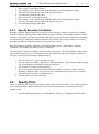
In order to improve solution time for the purposes of this tutorial certain finite-element options will be set. The
finite element mesh node limit and grid spacing will be set to generate a simpler mesh that will increase the
solution time.
8.
9.
10.
11.
12.
Select Model > FEM Options from the menu to open the FEM Options dialog.
Set the NODELIMIT as 800. (This is the student version maximum)
Set the NGRID parameter to 5. (This is the student version maximum)
Press OK to close the FEM Options dialog.
Press OK to close the Settings dialog.
Define Material Properties
2.7.3
The next step in defining the model is to enter the material properties for the single soil that will be used in the
model.
1.
2.
3.
4.
5.
6.
7.
8.
9.
10.
2.7.4
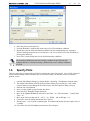
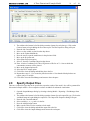
Open the Soils Manager dialog by selecting Model > Soils > Manager… from the menu.
Click the New Soil button to create a soil. The Soil Properties dialog will open automatically.
Double-click on the new soil to open the Soil Properties dialog.
Enter the information above into the appropriate fields on the Description tab.
Move to the Dispersion tab.
Refer to the data provided at the beginning of this tutorial. Enter the Longitudinal Dispersivity, aL
= 1m.
Enter the Transverse Dispersivity, aT = 1m.
The Diffusion option is set to Constant as the gradient file specified does not contain volumetric
water content, which is required to define a diffusion curve.
Enter the Diffusion Coefficient, D* = 0m2/day.
Close the Soil Properties and Soil Manager dialogs.
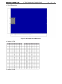
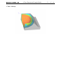
Specifying a Soil by Region and Layer
Each region will cut through all the layers in a model creating a separate “block” on each layer. Each block
can be assigned a soil or be left as void. A void area is essentially air space. In this model all “blocks” will be
assigned a soil.