1
INCLINOMETER
RS232 - CURRENT
Installation
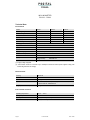
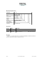
- Electrical Connection
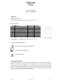
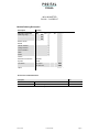
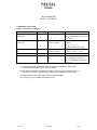
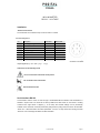
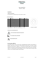
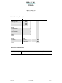
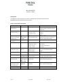
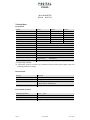
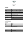
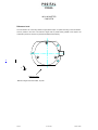
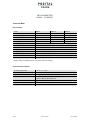
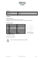
The inclinometer is connected via 8 pin round connector or a Cable
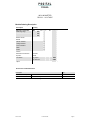
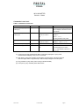
Connector Assignment
Pin
Description
P8F-Cable
CRW-Cable
1
+UB Supply voltage
white
white
2
RxD
brown
brown
3
TxD
green
green
4
Ground (Supply)
yellow
yellow
5
X-Output
grey
grey
6
S-Ground
pink
pink
7
Y-Output
blue
red
8
red
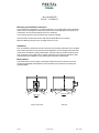
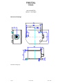
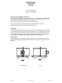
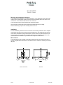
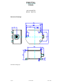
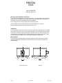
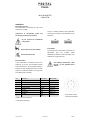
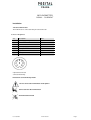
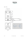
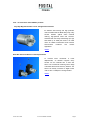
Front view of housing
Connector inclinometer
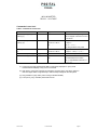
output signal (X,Y) analog current 4…20mA (+x,y°... -x,y°)
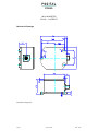
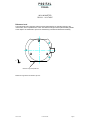
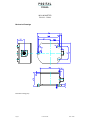
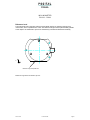
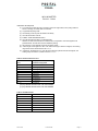
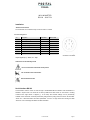
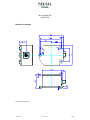
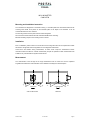
Instructions to mechanically install
Do not connect the inclinometer under power!
Do not stand on the inclinometer!
Avoid mechanical load!
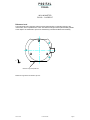
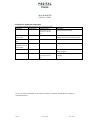
Serial Interface RS 232
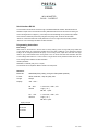
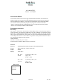
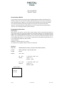
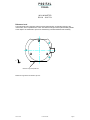
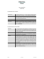
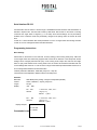
Communication with the sensor is done through a standardized RS-232 interface. Data transmission is
effected in duplex mode. The baud rate is fixed by 9600 baud. After Power On the sensor is sending
continuous the angle values in degrees (°). In the setup level several settings can be permanently
modified. If the continuous mode was permanently changed to the polling mode, the sensor will send after
”Power On” a start information with actual parameters. On error no angle values are sending and after
“Power On” a error message was add to the start information.
Issue: 01/06
E Info AGS-SC
Page 3