1
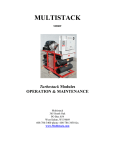
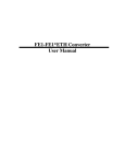
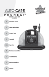
pCO3 Controller User Manual for ASP_X Made in U.S.A. Table of Contents Introduction............................................................................... 4 Flow Bypass............................................................................. 12 Module Board............................................................................ 4 Temperature Readings............................................................. 12 Master Controller....................................................................... 4 Master Controller Keys......................................................... 4 Time and Date.......................................................................... 12 Controller Setup......................................................................... 5 Manual/Off/Auto Switch............................................................ 5 Main Menu................................................................................. 5 On/Off Control Screen................................................................. 5 System Variables........................................................................ 6 Mechanical Cooling System Variables.................................. 6 Standard Application........................................................... 6 System Variable Ranges & Default Settings......................... 6 Standard Module Cutouts and Reset Points......................... 7 Customer Resets....................................................................... 13 Security.................................................................................... 13 Board LED’s.............................................................................. 13 Program Version....................................................................... 13 BAS Interface........................................................................... 13 Modbus............................................................................. 13 BACnet............................................................................... 14 LonWorks Bridge...................................................................... 14 APPENDIX A - Dipswtich Setup................................................. 15 Mechanical Cooling (Auto Mode)............................................... 7 APPENDIX B - System Variable Ranges..................................... 16 Mechanical Cooling – Manual Mode.......................................... 8 Manual Mode Ranges and Default Settings......................... 8 Low Ambient Application......................................................... 17 System Variable Ranges & Default Settings....................... 17 Module Cutouts and Reset Points....................................... 17 Master Controller Status Screens................................................ 9 System Screens.................................................................... 9 Mechanical Cooling Screens................................................. 9 Inputs and Outputs.................................................................. 10 Master Controller Inputs.................................................... 10 Master Controller Outputs.................................................. 10 Module Board Inputs......................................................... 10 Module Board Outputs....................................................... 10 Low Temperature Application.................................................. 17 System Variable Ranges & Default Settings....................... 17 Module Cutouts and Reset Points....................................... 17 APPENDIX C - Inputs And Outputs............................................ 18 Master Control......................................................................... 18 Module Boards......................................................................... 19 Faults....................................................................................... 11 System Faults..................................................................... 11 Mechanical Cooling Module Faults..................................... 11 APPENDIX D - Compressor Rotations........................................ 20 Fault Review............................................................................ 12 APPENDIX F - Free Cool Modules.............................................. 22 APPENDIX E - Remote Display.................................................. 21 Load Profile.............................................................................. 12 3 Introduction An Airstack Air-cooled Packaged Chiller (ASP) is a modular air-cooled chiller system, composed of one or more modules controlled by one master controller, to provide chilled liquid to an external circuit. Each chiller system may be composed of up to 14 mechanical cooling modules. These mechanical cooling modules interconnect through a common chilled water header system. Each module contains 2 scroll compressors, a stainless steel brazed plate heat exchanger, copper tube with aluminum fin condenser coils, two fans, and other related control components. Each ASP chiller system is operated by a microprocessor based controller that monitors the status of each refrigerant circuit and provides a signal to operate compressors and fans as required. The system uses the entering chilled water temperature (ECHWT), when in auto mode, to determine the need for cooling to the external circuit. Module Board Each module has a module board, which sends information to the master controller regarding the temperatures, pressures, and activity of the module. The feedback from the module board determines the status of its circuits. The module board performs safety checks and alerts the master controller when something is wrong. Loss of communication with the master controller results in the shutting down of the module, unless the module is running in manual mode. Master Controller The master controller is equipped with a 4x20 character LCD with backlight and a six button keypad. These aid the operator in setting SYSTEM VARIABLES, checking faults, monitoring the status of the chiller system, and monitoring the status of individual modules. The master controller is also the interface to field supplied remote connections such as Remote Start/Stop, flow switch inputs, customer alarm outputs, and CHILLED WATER RESET and LOAD LIMIT RESET signals. There is also an optional communication link for remote monitoring and control of the chiller system. Master Module Controller Keys The UP arrow button is used to go back to the previous category on the screen or to increase the value of a digit in a numeric variable field. The DOWN arrow button is used to advance to the next category on the screen or to decrease the value of a digit in a numeric variable field. The ENTER button is used to make a selection from any of the menu screens in the program. It is also used to enter and exit edit mode while in the SYSTEM VARIABLES screens. The ALARM button is the menu for current system or module faults. When the backlight is red, it indicates that a fault has occurred. The PROGRAM button goes to the MAIN MENU from any screen in the program. The ESCAPE button goes to the previous screen or the status screen, if you are at the top of the MAIN MENU. ASP Module 4 Controller Setup The Master Control and Module Boards’ address are set electronically by simultaneously pressing and holding the ALARM and UP buttons while cycling power on. After a few seconds a screen configuration will appear, to modify the address use the UP and DOWN buttons, and then press ENTER to confirm and save. The following are the addressing parameters for setting up a Multistack Chiller network: Heat Pump Modules – 1 thru 14 Master Controller – 30 Remote LCD Display – 32 In setting up the network, the master controller must have an address of 30. The heat Pump modules would start with module 1 and proceed numerically through module 14. Once all addresses are set you should do a Factory Reset to sync the communication network. To do a Factory Reset power up all modules, cycle power at the Master Control using the 1 pole 24V breaker. Once the 12 second count down appears push and hold the PRG and UP arrow keys simultaneously for 4 seconds and release. This completes the Factory Reset, now you can set the variables. Manual/Off/Auto Switch Each MagLev module has a Manual/Off/Auto switch. In manual mode, the loading of the compressor is done by the module board. The control is independent of the other modules and is based on the LCHW temperature of that module. When auto mode is selected, the staging of the compressors is handled by the master controller. The master controller will determine how many compressors need to be on in order to satisfy the load requirements. Control of the compressors is based on the system LCHW temperature when in auto mode. Disabled mode (off) selection disables the module and the compressor is not allowed to run. Main Menu The MAIN MENU displays the options the user can access in the program. Press the Prg button to get to the MAIN MENU and then use the UP and DOWN arrow buttons to scroll through the menu. The ENTER button allows displaying of the sub-menu that the greater than sign (>) is located beside. The MAIN MENU contains ON/OFF CONTROL, STATUS, SYSTEM VARIABLES, FAULT REVIEW, LOAD PROFILE, SECURITY, and BAS INTEFACE. On/Off Control Screen Upon power up, the initial screen will go through a 12 second delay before giving control to the user. The ON/OFF CONTROL screen will be the next screen. It allows the user to command the chiller on or off. The display will read ‘CHILLER OFF, PUSH ENTER TO START’. Pushing the ENTER button, will display a message of ’30 SECONDS TO START!’ and will change to ‘CHILLER ON, PUSH ENTER TO STOP’. After the 30 second delay, the first compressor will turn on and the display will change to the status screen. The last line of the screen also can show critical system faults such as WAITING FOR CHW FLOW and WAITING FOR EX2 INPUT. System Variables Once power is connected to the master controller, the SYSTEM VARIABLES can be accessed. These variables determine how the chiller system will run and are assigned a default value. For most installations, these values will provide optimum performance. However, special operating conditions may require different settings. Use the UP or DOWN arrow buttons to locate the SYSTEM VARIABLES in the MAIN MENU. The greater than sign (>) is the cursor indicator. Press the ENTER button to enter the SYSTEM VARIABLES’ MENU. Press the ENTER button again to enter one of the sub-menus. To change the value of a variable, press the ENTER button. A blinking block cursor will appear in that system variables’ value field indicating that the program is in edit mode. Use the UP or DOWN arrow buttons to change the value of the variable. To save the new setting, press the ENTER button, pressing the Esc button will not save the change. The cursor will move back to the upper left corner of the screen indicating that the program is no longer in edit mode. An asterisk (*) next to the variables indicates that the SYSTEM VARIABLES are locked and cannot be adjusted. For assistance on unlocking the SYSTEM VARIABLES, see SECURITY on page 14. Mechanical Cooling (System Variables) The following is a list of SYSTEM VARIABLES for the mechanical cooling modules: 1. UPPER SETPOINT: The entering chilled water temperature (ECHW – System sensor) at full load. When the water entering the chiller is at or above this setpoint, all available compressors should be running. 2. LOWER SETPOINT: The leaving chilled water temperature (LCHW – System sensor) at full load. The temperature drop across this chiller is based on flow rate. If the design temperature drop (∆T) is 10°F across the chiller, then the LOWER SETPOINT should be 10°F below the UPPER SETPOINT. 3. VSP SETPOINT: A percentage used to determine the no load chilled water temperature. If the UPPER SETPOINT is at 55°F, the LOWER SETPOINT is at 45°F, and the VSP is at 50%, then the no load point would be 50% of the difference between the UPPER SETPOINT and the LOWER SETPOINT settings, which is 10°F. Therefore, all compressors would be on a 55°F and all compressors would be off at 50°F by the temperature of the ECHW Sensor. 5 4. LOAD LIMIT: A percentage used to limit the maximum system load. If this variable is set to 75% on a 4 compressor chiller, then only 3 of the compressors would be available to run at any given time. 5. T-DIFF: (Time Difference) The minimum time in seconds between starts of compressors. This time should be set to half of the loop time. The loop time is the time it takes for the water to make one pass through the entire CHW loop of the building. When the temperature of the ECHW becomes close to the required temperature, T-Diff goes to 2 times T-Diff. When unloading compressors, T-Diff goes to half of T-Diff. 6. FAIL INDIC : (Failure Indicator) A percentage value which provides for an output signal whenever compressors of the indicated value have failed. A 0% setting will give an output signal after any failure within the system. 7. LEAD COMP: Determines which compressor is the first on and the last off. The compressors will appear in a format of M1-1, M1-2, M2-1, etc. This format stands for Module #1 –Compressor #1 and so on. See Appendix D on page 23 for more information on compressor rotations. 8. MAN. SETPOINT: Please see page 8 on manual mode operation for further details. 9. MAN RANGE: Please see page 8 on manual mode operation for further details. 10.MAN OFFSET: Please see page 8 on manual mode operation for further details. 11.NUM OF MODULES: This is the number of mechanical cooling modules that are in the chiller system. 12.FAN SETPT: The point, measured in psig, where the last fan turns off. 13.FAN OFFSET: The value, measured in psig, when added to the FAN SETPOINT where the first fan turns on. When psig reaches 2 times the FAN OFFSET, the second fan will turn on. Ex. If the FAN SETPOINT is at 235 psig and the FAN OFFSET is at 30 psig, the first fan will come on at 265 psig and the second at 295 psig. They will then turn off at 265 psig and 235 psig. 14.HP CUTOUT: The point where a high pressure fault occurs based on the high pressure transducer. Note: Each module also has a mechanical high pressure switch with a manual reset. If this setting is set higher than the switch setting, the mechanical switch will take the module offline with a high pressure fault. 15.SEQUENCE: Determines the order in which the compressors will turn on or off. STANDARD – The compressors turn on in numerical order starting with the lead compressor. ODD/EVEN – A scheme developed to bring one compressor in each module on before the second compressor in any module is allowed to run. If the LEAD COMPRESSOR ends in -2 (M1-2, M2-2, etc), then all even compressors would start before the odd compressors. If the LEAD COMPRESSOR ends in -1 (M1-1, M2-1, etc), then all add compressors would start before the even compressors. See Appendix D on page 23 for more information on compressor rotations. 16.INDEXING: The indexing can either be ON or OFF. If ON, the lead compressor advances by one every 24 hours at midnight. If OFF, the LEAD COMPRESSOR stays the same and will have the most runtime. See Appendix D on page 23 for more information on compressor rotations. Standard Application Program Version Format: MCTS_A00-SE System Variable Ranges & Default Settings Mechanical Cooling The following table defines all of the SYSTEM VARIABLE ranges and default values for ASP-X modules with the standard program. SYSTEM VARIABLE UPPER SETPOINT LOWER SETPOINT VSP VALUE LOAD LIMIT T-DIFF FAIL INDIC LEAD COMP. NUM OF MODULES MANUAL SETPOINT MANUAL RANGE MANUAL OFFSET FAN SETPOINT FAN OFFSET HP CUTOUT SEQUENCE INDEXING 6 RANGE 45°F to 80°F 40°F to 70°F 0% to 80% 0% to 100% 15 to 200 sec 0% to 90% M1-1 to M14-2 1 to 8 40-70 2-20 0-5 170-350 20-60 40 to 590 psig STD/ODD-EVEN OFF or ON DEFAULT VALUE 55°F 45°F 0% 100% 90 sec 0% M1-1 1 45 10 2 325 50 585 ODD/EVEN ON Standard Module Cutouts and Reset Points Low Suction Temp Reset @ 30°F Cutout 4 25°F Low Leaving CHW Reset @ 40°F Cutout 4 36°F High Pressure Reset below 325 psig Cutout 4 HP Cutout Value ** Special low temperature applications are available under supervision of Multistack. Auto Mode Chilled Water Reset for Temperature Control The following chart defines how the chiller works in auto mode. It is based on a 10 compressor system (5 modules) with a 10°F ∆T, and operation between 55°F and 45°F. It shows the system relationship between ECHWT, LCHWT, and VSP at various load conditions. ECHW System Temp. (Control Setpoint) 55 54 Upper Setpoint=55.0 53 T E M P (°F) VSP=80% 52 51 50 VSP=50% 49 48 Lower Setpoint=45.0 47 VSP=20% 46 LCHW System Temp. 45 90 80 70 60 50 40 30 20 10 0 % Of Load 10 9 8 7 6 5 4 3 2 1 0 Compressors System Conditions: Full Load ∆T = 10 °F 10 Compressors UPPER SETPOINT - 55 °F LOWER SETPOINT - 45°F The data below shows same operating conditions that could occur based on the information from the chart: % LOAD 0 50 100 VSP = 20 % ECHWT 47 51 55 LCHWT 47 46 45 % LOAD 0 50 100 VSP = 50 % ECHWT 50 52.5 55 LCHWT 50 47.5 45 % LOAD 0 50 100 VSP = 80 % ECHWT 53 54 55 LCHWT 53 49 45 7 Mechanical Cooling – Manual Mode In manual mode operation, each module acts independently, depending on the sensor inputs to that module. The staging of the compressors is done by its module board. The control is based on the LCHW temperature of that module. The following are SYSTEM VARIABLES that are used in manual mode operation: 1. MAN. SETPOINT: The LCHW temperature where the last compressor will turn off. 2. MAN. RANGE: A value, when added to the MAN. SETPOINT where the first compressor will turn on. 3. MAN. OFFSET: A value, when added to the MAN. RANGE point where the second compressor will turn on. Caution: Operation of chiller in manual mode bypasses the flow protection and power phase monitor safeties. Operation of the chiller in this mode is not recommended for extended periods. Proper precautions must be made to prevent freezing of the heat exchangers. Manual mode Ranges and Default Settings System Variable MAN. SETPOINT MAN. RANGE MAN. OFFSET Range 40°F to 70°F 2°F to 20°F 0°F to 5°F Default Value 45°F 10°F 2°F Offset = 2.0°F 57°F Turn Comp. 2 ON 55°F Turn Comp. 1 ON Range =10.0°F 47°F Turn Comp. 2 OFF SETPOINT=45.0°F 8 45°F Turn Comp. 1 OFF Master Controller Status Screens System Screens The main status screen displays information about the chiller system. 1.CAPACITY: A percentage of how many compressors are turned on, compared to the total installed. An asterisk (*) displayed next to capacity indicates that it is being controlled by an external source, either LOAD LIMIT or CHILLED WATER RESET. 2.DEMAND: A percentage of current load needed compared to the maximum design load. This value is determined by the system ECHW temperature and the settings of the SYSTEM VARIABLES. 3.DELAY: A time in seconds between start up of compressors. A compressor should only turn on or off if the delay time counter is at zero. This is determined by the mechanical cooling module’s system variable T-DIFF. 4.FAULTS: A value showing how many current faults are in the system. 5.ECHW: The Entering Chilled Water temperature in the system. 6.LCHW: The Leaving Chilled Water temperature in the system. Press the DOWN arrow button once to display the next main status screen with system information. 1.LEAD COMP: The compressor shown is the first on and the last off. Displayed as M1-1, M1-2, M2-1, etc. format. (M1-1 represents Module #1, Compressor #1) 2.LOAD LIMIT: A percentage value to limit the max number of compressors available at any given time. An asterisk (*) indicates the external LOAD LIMIT RESET signal is enabled. 3.CHW OFFSET: Shows value of customer CHW RESET signal. Range 0 to 10°F. An asterisk (*) indicates the external CHW RESET signal is enabled. Mechanical Cooling Screens – Master Controller Press the DOWN arrow button again to display information for the first mechanical cooling module. The following information is available: 1.LCHW: The Leaving Chilled Water temperature in the module measured leaving the evaporator coil. 2.SUCT: The Suction temperature in the module measured on the compressor suction line. 3.COMP 1 and COMP 2: This displays the status of the compressors, ON or OFF. 4.Status Line: The status line of the module can be the mode in which the module is in or it can be what the current fault is on that module. If nothing appears in the status portion of the screen, then the module is in auto mode and there are no faults. If MANUAL MODE or DISABLED appears on the status line, then the module is in manual mode or disabled mode. The faults that occur on the modular level will also be displayed on the status line when the fault is current. Press the DOWN arrow button again to display screen #2 for the first module. Information on this screen is as follows: 1.RUN HOURS: COMP1 and COMP2: This displays the total number of hours that each compressor has run. To reset the run hours of compressor 1, press and hold the ALARM and DOWN arrow buttons simultaneously on the screen of the module whose hours need to be reset. To reset the run hours of compressor 2, press and hold the PRG and UP arrow buttons simultaneously on the screen of the module whose hours need to be reset. The SYSTEM VARIABLES must be unlocked to clear compressor run hours. 2.FAN 1 and FAN 2: Displays the status of the fans, ON or OFF. FAN 2 will always be the first fan on. 3.HP and LP: This displays the amount of pressure in psig for the high side and low side pressures in each module. Press the DOWN arrow button now to display screen #1 for module 2. From there, screen #2 for module 2 and then screen #1 for module 3 and so on. 9 Inputs and Outputs Master Controller Inputs 1.Customer Chilled Water Reset Signal: A 0-10Volt, 0-20 mA, or 4-20 mA, customer supplied, external signal that shifts the UPPER and LOWER SETPOINTS from 0 to 10°F. 2.Customer Load Limit Reset Signal: A 0-10Volt, 0-20 mA, or 4-20 mA, customer supplied, external signal that allows the customer to change the LOAD LIMIT from 0 to 100%. 3.Entering Chilled Water Sensor: A NTC type sensor that measures the temperature of the system ECHW going to the mechanical cooling modules. 4.Leaving Chilled Water Sensor: A NTC type sensor that measures the temperature of the system LCHW coming from the mechanical cooling modules. 5.EX1: A customer supplied input that is a closed circuit to operate; open to stop operation. Requires manual reset to resume operation. This input will create a fault. 6.Remote Start/Stop: An input that is a closed circuit to operate; open to stop operation. Automatic restart of the chiller. This input does NOT create a fault. 7.Power Phase Monitor: An input that is a closed circuit to operate; open to stop operation. Automatic restart returns the chiller to the previous on/off state of the chiller. This input will create a fault. 8.CHW Flow Switch: An input that is a closed circuit to operate; open to stop operation. Circuit opens when there is NO FLOW in the system. After 4 seconds, the chiller shuts down. When the flow switch closes, the chiller will automatically restart. This input will create a fault. Master Controller Outputs 1.Customer Alarm Relay: This is a 24VAC, 5VA max signal that can be used to power a relay to trigger an alarm. The output is controlled by the failure indicator setting in the SYSTEM VARIABLES for mechanical cooling. 2.Full Load Indicator Relay: This is a 24VAC, 5VA max signal that can be used to power a relay to show that the chiller system is at full load (all available compressors on). 3.Run Status Relay: This is a 24VAC, 5VA max signal that can power a relay to show that at least one compressor is running in the chiller. 4.Remote Pump Enable: This is a contact closure, 5VA max signal that can be used to remotely enable the pump module. This contact will be closed anytime the chiller is commanded ON. When the chiller is turned OFF, the pump will continue to run for two times the TDIFF setting. If the Power Phase Monitor trips, the contact will open with no time delay. Module Board Inputs 1.High Pressure Transducer: A 4-20 mA input sensor that measures the high side pressure of the refrigerant in each module. 2.Low Pressure Transducer: A 4-20 mA input sensor that measures the low side pressure of the refrigerant in each module. 3.Suction Sensor: A NTC type sensor that measures the temperature of the suction line. 4.Leaving Chilled Water Sensor: A NTC type sensor that measures the temperature of the LCHW in the module. 5.Manual Mode/Auto Mode: Inputs that identify whether the module is in manual, auto, or disabled mode. 6.High Pressure Switch: An input that indicates when the switch for the high side pressure of the refrigerant circuit has tripped. 7.Circuit Faults: An input that monitors the control circuit of each compressor for abnormal operating conditions. A 1 or 2 would be displayed to show which compressor circuit has a fault. Module Board Outputs 1.Compressor Start Signal: A 24VAC output used to energize the compressor contactors when there is a call for cooling. 2.Liquid Line Solenoid Valve: A 24VAC output to energize the liquid line solenoid valve 5 seconds before either compressor starts. Output is de-energized when both compressors are off. 3.Fan Start Signal: A 24VAC output used to energize the fan motor starters. 4.Alarm Light: A 24VAC output that energizes a light in the control panel of the module that is in a fault condition. 10 Faults If a fault has occurred, the ALARM button will illuminate. To view the current fault(s), press the ALARM button. Use the UP and DOWN arrow and ENTER buttons to view and clear the fault(s). If the fault returns, then it will need to be reset elsewhere first. System Faults If any of the following faults occur, all compressors in the system will be turned off, unless the individual module is in the manual mode. ** 1.EX1: Customer Input – EX1 requires a reset at the master controller. 2.Remote Start/Stop: Customer Input – EX2 is NOT a fault. This circuit operates like an on/off switch. If closed, the chiller is on, if the chiller has been commanded on. If open, chiller is disabled and the compressors will not run. 3.Power Phase Monitor: Customer Input – EX4 does create a fault. There is no reset required at the master controller. If the chiller is on when fault occurs, it will default back to on after the fault clears. 4.CHW Flow: This alerts the master controller of NO FLOW in the system and disables all modules in auto mode. There is an automatic restart after the flow switch closes. If the flow switch opens and the chiller has not been commanded ON, a warning will appear at the bottom of the start/stop screen, however, no fault will occur. 5.LOCHW Temp: Low Leaving Chilled Water temperature. If the system LCHW falls below 36°F, all compressors will turn off. The water temperature must rise to 40°F before the fault can change from current to reset. This requires resetting the fault and restarting the chiller at the master controller. 6.ECHW Sensor Failure: The sensor for the system ECHW has either opened or shorted to the master controller. This fault requires resetting at the master controller. 7.LCHW Sensor Failure: The sensor for the system LCHW has either opened or shorted to the master controller. This fault requires resetting at the master controller. Mechanical Cooling Module Faults The following faults will only affect the module that they are associated with. 1.High Pressure: High Pressure Cutout. This high pressure fault can come from either the transducer reading or the HP switch being tripped. If the HP transducer reaches the pressure of the HP Cutout variable the alarm goes off, shutting down that module. In this case, the fault only needs to be reset at the master controller after the high side pressure drops below 300 psig. If the HP switch trips then, it requires resetting at the module HP switch and the master controller to resume operation. The fault will remain current until the HP switch is manually reset. 2.HP Sensor Failure: The High Pressure Transducer has either opened or shorted to the master controller. This fault requires resetting at the master controller. 3.Low Pressure: Low Pressure Cutout. If the reading from the LP transducer falls below 15 psig, then that module will be shut down and in an alarm state. This fault will remain current until the low side pressure rises above 25 psig. The fault can then be reset at the master controller. (Typically indicates loss of refrigerant charge.) 4.LP Sensor Failure: The Low Pressure Transducer has either opened or shorted to the master controller. This fault requires resetting at the master controller. 5.Low Pressure Delay: A Low Pressure Delay occurs when the low side pressure drops to below 25 psig, disabling the compressors in that module for 5 minutes. This fault automatically resets after the 5 minutes, as long as the low side pressure reading is above 30 psig. 6.Circuit Fault: A CIRCUIT FAULT will occur if the compressor contactor is not operating normally. Four conditions could potentially create a CIRCUIT FAULT. One would be, if the program signals for a contactor to be closed and it does not close within 5 seconds. Once the contactor has been closed for 5 seconds, if the contactor ever opens for 1 second while under normal operating conditions (indicating a chattering contactor), a fault will occur. The third condition would be if the program turns a contactor off and the contactor remains closed for an additional 10 seconds, this fault would occur (indicating a welded contactor). The last condition that could create a circuit fault is if the difference between the high pressure and the low pressure is not greater than 50 psig after the compressor starts within 60 seconds. This fault requires resetting at the master controller to resume normal operation. 7.LOSUCT: Low Suction Temperature: This is measured by the module suction sensor and would affect the entire module. If during operation this temperature should drop below 25°F, the module’s compressors will shut down. This requires resetting at the master controller, but only after the temperature has risen above 30°F. The system has to be on for this fault to occur. 8.SUCT SENSOR FAILURE: Suction Sensor Failure. This would occur if the suction line sensor opened or shorted to the module board. This fault requires resetting at the master controller. 9.LOCHW TEMP: Low Leaving Chilled Water Temperature: This is measured by the module LCHW temperature sensor. In a standard application if the temperature falls below 36°F, the module compressors turn off. The temperature must rise to 40°F before the fault can be reset at the master controller. (cont’d on next page…) 11 10. LCHW SENSOR FAILURE: Leaving Chilled Water Sensor Failure: This would occur if the sensor opened or shorted to the module board. This fault requires resetting at the master controller. 11. COMMUN: Communication Error. This would occur if more than one module is addressed the same, or if there is a problem with communications of that individual module to the master controller. This fault only occurs in auto mode. Fault Review The FAULT REVIEW is a history of the faults that have occurred in the chiller system. The review holds up to 25 faults. The review can be found in the MAIN MENU. The faults are in order by the most recent to the oldest. Pushing the UP and DOWN arrow buttons allows scrolling through the faults. Pushing the ENTER button on a particular fault allows for viewing of a second screen of information. Pushing ENTER again returns to the first screen of the fault. The following is a sample of what the two screens contain. FAULT 01 CURRENT COMMUNICATION ERROR MOD1 9/17 12:35 PRESS ENTER FOR MORE Screen #1 FAULT 01 *SYSTEM *ECHW 00.0 *LCHW 00.0 SUCT LCHW HP = LP = 00.0 00.0 000 000 Screen #2 Screen one displays information about the fault. The status of the fault will be displayed as CURRENT, RESET, or RECORD. CURRENT means that the fault is still present, RESET means that the fault can be reset at the master controller, and RECORD means that the fault is part of the history for future reference. The date and time of the fault, the fault that occurred and where the fault occurred are also displayed on the first screen. On screen two, the system temperatures at the time the fault occurred will be displayed on the left side of the screen and are starred with an asterisk (*). On the right side of the screen is module information that was current at the time of the fault. If the fault is a system fault the module information will display all zeros. Clearing the faults from the FAULT REVIEW removes all the faults at once. Hold down the Prg and UP arrow buttons simultaneously for all faults to be removed from the FAULT REVIEW. When a message of NO MORE ALARMS appears on the screen, release the buttons. Load Profile The LOAD PROFILE displays the operating history of the mechanical cooling modules. It relates the total operating hours to the load percent and is subdivided into 10% segments. This screen is located in the MAIN MENU of the master controller. There are three screens used to display the information. Pressing the DOWN arrow button will allow all screens to be viewed. To reset the hours in the LOAD PROFILE, hold down the DOWN arrow and the ALARM buttons simultaneously while viewing the LOAD PROFILE. The SYSTEM VARIABLES must be unlocked to clear the LOAD PROFILE. Flow Bypass The FLOW BYPASS is located in the SYSTEM VARIABLES’ MENU. Flow Bypass should be ENABLED when the Normally Open Water Solenoid Valves (N.O. WSLV) installed in the Lead Module is required to remain open or de-energized at all times. Press ENTER on FLOW BYPASS to ENABLE or DISABLE. When ENABLED, the N.O. WSLV will always remain open on the Lead Module. On the modules that are not currently the Lead Module or when DISABLED, the N.O. WSLV will be energized and close the valve after 60 seconds of no compressors running in that module. The LCHW temperature in that module must also remain above the 36°F cutout in the Standard and Low Ambient applications. If the LCHW temperature drops below 36°F, the valve in that module will be de-energized and open. The valve will remain open until the LCHW temperature rises above 40°F when the N.O. WSLV will again be energized and close if no compressors are running in that module. Temperature Readings The temperature readings default to Fahrenheit (°F). The readings may be set to display in Celsius (°C), by going to the SYSTEM VARIABLES’ MENU. Press ENTER on TEMP. READINGS option. Press ENTER again to move the cursor into the field. Use the UP or DOWN arrow button to change the field from Fahrenheit to Celsius. Press ENTER again to accept the change. Time and Date The TIME AND DATE option is located in the SYSTEM VARIABLES’ MENU. Press ENTER on the TIME AND DATE option. The time appears first and is displayed in military time. To change the time, press the ENTER button, putting the program into edit mode. The cursor is now in the hour field, use the UP and DOWN arrow buttons to change the hour to the correct time. Press the ENTER button again to move the cursor to the minute field to change it. Press the ENTER button one more time to set the TIME. Press the Esc button, at anytime, to abort the time change. After setting the TIME, use the DOWN arrow button to move to the DATE screen. Press ENTER to move the cursor into the month field. Using the UP and DOWN arrow buttons, change the value to the current month. Press ENTER again to move the cursor to the day field, adjust the day accordingly. Press ENTER again to move to the year field, adjust the year accordingly. Press ENTER one more time to accept the DATE. Press the Esc button, at anytime, to abort the date change. 12 Customer Resets CHILLED WATER RESET (CHW) and LOAD LIMIT RESET are external inputs that are program selectable as 0-10Volt, 0-20 mA, or 4-20 mA. The customer can send a signal to change these values remotely. The CHW RESET will increase the UPPER and LOWER SETPOINTS in the mechanical cooling modules anywhere from 0 to 10 °F. The LOAD LIMIT RESET will allow the LOAD LIMIT of the mechanical cooling modules to be changed. There will be an asterisk (*) by the CHW OFFSET and the LOAD LIMIT values on the second system status screen, if they are enabled. The CUSTOMER RESET options are located in the SYSTEM VARIABLES’ MENU. An asterisk (*) also appears next to CAPACITY on the main status screen when either reset is enabled. Press ENTER and use the UP and DOWN arrow buttons to change the value. Both default to OFF, but when enabling the user must select the type of input being used. (0-10 Volt, 0-20 mA, or 4-20 mA) Security The security option in the MAIN MENU is used to lock the SYSTEM VARIABLES. The first screen tells whether the variables are locked or unlocked. Initially the screen will say ‘SYSTEM VARIABLES UNLOCKED’. Press ENTER to change the status of the security. The cursor will be on the first letter of the password code. Enter a five letter password, using the UP and DOWN arrow buttons to change the letter and press ENTER to move to the next letter. After entering the last letter, the next screen is to accept the password or clear the password. Press ENTER again to set the password or Esc to clear the password. The screen will then display the status of the SYSTEM VARIABLES as LOCKED. An asterisk (*) is displayed within the SYSTEM VARIABLES’ MENU in place of the greater than sign (>) as a cursor for the menu. If the asterisk is seen, the SYSTEM VARIABLES need to be unlocked before trying to make any changes to them. If the password is forgotten, please call your Multistack Service Representative at 608-786-3400. Board LED’s Five LED’s are present on each board, master and module. Two LED’s are located at the bottom of the board, one yellow and one red. The yellow one indicates that the board is receiving power. The red one is an alarm LED that would indicate that something maybe wrong with the board internally. Three more LED’s are located at the top of the board next to the DIP switches. These LED’s indicate that the connection, address definition and pLan (network of the modules) are working correctly. The green and yellow LED’s should be lit for the network to be working properly. Program Version The program version is found by going to the Main Menu and pressing the PRG and UP arrow buttons simultaneously. A screen will appear that displays the version of the program in the controllers and the month and year the program was developed. The version will appear in a format similar to MCAS_A01. When looking at the version, the forth position could vary between S, L, and B. The S stands for a Standard application, the L for a Low Ambient application, and the B for a Brine or Low Temperature application. This each of these programs may have different cutouts or temperature ranges available to the customer. The standard application system variables and cutouts are located on page 6. The system variables and cutouts for the low ambient and low temperature applications are found in Appendix B on page 18. BAS Interface The master controller is capable of tying into a building automation system. This is an optional feature to the chiller system. Modbus, BACnet, and LonWorks are currently available. First, the BAS INTERFACE needs to be enabled. This is accomplished by going to the SYSTEM VARIABLES Menu and changing the enable point, under BAS INTERFACE, to yes. The enable defaults to no. This menu also has a variable to select which Protocol will be used. Select the appropriate Protocol for the job. BACnet is the default for this variable. Modbus Modbus requires that a RS485 card is installed into the pCO2 Master Controller. This card plugs into the serial port and communicates Modicon Modbus Protocol Rev. D. The Modbus protocol used is RTU type. The configuration is multipoint for RS-485. The data communication is asynchronous serial, 8 data bits, 2 stop bits, and no parity across an EIA-485 two-wire half-duplex connection. The cable size recommended is an AWG20/22 two-wire twisted shielded cable. The pin wiring is GND, RX+/TX+, RX-/TX- and is stamped on the terminal connector. The customer can adjust the Baud Rate and the Network Number. These settings are found in the SYSTEM VARIABLES Menu under BAS INTERFACE. The Baud Rate defaults to 9600 bps and can be adjusted to 1200, 2400, 4800, 9600, or 19200 bps. The ID Number is the same as a slave address and defaults to 1. This number must be unique to the Modbus network. The range for the ID Number is from 1-200. For more information on the Modbus configuration, please see the Technical Manual for Modbus. Figure 1: RS485 Card Figure 2: pCO2 with RS485 Card 13 BACnet BACnet over TCP/IP or Ethernet requires a pCO Web Card (Figure 3) to be installed into the pCO2 Master Controller. This card plugs into the serial port and communicates BACnet over Ethernet (ISO8802-2 over 8802-3) or BACnet over TCP/IP (Addenda A/Annex J). The recommended cable is shielded class 5, max 100mt. The Baud Rate is selectable and defaults to 19200. The ID Number is also selectable and defaults to 1. This variable can remain at 1 for the TCP/IP and Ethernet connections. For more information on the BACnet over TCP/IP or Ethernet configuration, please see the Technical Manual for BACnet over TCP/ IP or Ethernet. BACnet over MS/TP (Master Slave Token Passing) requires a pCOnet Card (Figure 5) to be installed into the pCO2 Master Controller. This card plugs into the serial port and communicates BACnet over an RS-485 2-wire connection. The Baud Rate is selectable and defaults to 19200. The ID Number is also selectable and defaults to 1. For more information on the BACnet over MS/TP configuration, please see the Technical Manual for BACnet over MS/TP. Figure 3: pCO Web Card Figure 4: pCO2 with PCO Web Card Figure 5: pCOnet Card LonWorks Bridge LonWorks communication is achieved by using a Modbus RS-485 Card (Figure 1) plugged into the pCO2 Master Controller to a FieldServer Bridge (Figure 6). The FieldServer Bridge is a device that translates Modbus to LonWorks. Using this device allows all the points available in the controller to be passed to the Lon Network. For more information on the LonWorks configuration, please see the Technical Manual for LonWorks. Figure 6: Fieldserver Bridge 14 APPENDIX A: DIPSWITCH SETUP The following are the positions of the DIP switches to setup the network of ASP’s. The black square represents the location of the switch. Mechanical Cooling Modules Module 1 Module 1 Module 1 Module 4 Module 5 Module 6 Module 7 Module 8 Module 9 Module 10 Module 11 Module 12 Module 13 Module 14 Master Module 15 APPENDIX B: SYSTEM VARIABLE RANGES Special Program Required: Program Version Format: MCAL_A01 System Variable Ranges & Default Settings Mechanical Cooling Modules The following table defines all of the SYSTEM VARIABLE ranges and default values for mechanical cooling modules with a low temperature program. System Variable UPPER SETPOINT LOWER SETPOINT VSP VALUE LOAD LIMIT T-DIFF FAIL INDIC LEAD COMP NUM OF MODULES MAN. SETPOINT MAN. RANGE MAN. OFFSET FAN SETPT FAN OFFSET HP CUTOUT SEQUENCE INDEXING Range 45°F to 80°F 40°F to 70°F 0% to 80% 0% to 100% 15 to 200 sec 0% to 90% M1-1 to M14-2 1 to 14 40°F to 70°F 2°F to 20°F 0°F to 5°F 170 to 350 psig 20 to 60 psig 300 to 425 psig STANDARD or ODD/EVEN OFF or ON Default Value 55°F 45°F 50% 100% 90 sec 0% M1-1 1 45°F 10°F 2°F 235 psig 30 psig 365 psig STANDARD ON Module Cutouts and Reset Points Low Suction Temp Cutout 20°F Reset @ 25°F Low Leaving CHW Cutout 36°F Reset @ 40°F Low Pressure Cutout 15 psig Reset @ 25 psig NOTE: LOW SUCTION FAULT The low suction fault in this application works differently then in the standard program. One compressor in the module must be on for at least 30 seconds before a low suction fault can occur. This delay should allow enough time for the suction gas line to warm up to normal operating conditions when starting in a low ambient environment. The chiller system must include glycol to prevent freezing of the evaporators in an off condition. 16 LOW TEMPERATURE APPLICATION Special Program Required Program Version Format: MCAB_A01 System Variable Ranges & Default Settings Mechanical Cooling Modules The following table defines all of the SYSTEM VARIABLE ranges and default values for mechanical cooling modules with a low temperature program. System Variable UPPER SETPOINT LOWER SETPOINT VSP VALUE LOAD LIMIT T-DIFF FAIL INDIC LEAD COMP NUM OF MODULES MAN. SETPOINT MAN. RANGE MAN. OFFSET FAN SETPT FAN OFFSET HP CUTOUT SEQUENCE INDEXING Range 25°F to 80°F 20°F to 70°F 0% to 80% 0% to 100% 15 to 200 sec 0% to 90% M1-1 to M14-2 1 to 14 25°F to 70°F 2°F to 20°F 0°F to 5°F 170 to 350 psig 20 to 60 psig 300 to 425 psig STANDARD or ODD/EVEN OFF or ON Default Value 40°F 30°F 50% 100% 90 sec 0% M1-1 1 45°F 10°F 2°F 235 psig 30 psig 365 psig STANDARD ON Module Cutouts and Reset Points Low Suction Temp Cutout 15°F Low Leaving CHW Cutout 20°F Low Pressure Cutout 15 psig Reset @ 20°F Reset @ 25°F Reset @ 25 psig NOTE: LOW SUCTION FAULT The low suction fault in this application works differently then in the standard program. One compressor in the module must be on for at least 30 seconds before a low suction fault can occur. This delay should allow enough time for the suction gas line to warm up to normal operating conditions when starting in a low ambient environment. The chiller system must include at least 25% of glycol to prevent freezing of the evaporators in an off condition. NOTE: LOW LEAVING CHW FAULT The low leaving CHW fault in this application works differently then in the standard program. The chiller must be commanded on for this fault to occur in the low temperature program. 17 APPENDIX C: INPUTS AND OUTPUTS MASTER CONTROL (UNIT WITH DISPLAY) 10, 15 and 20 TON MODULES Analog Inputs B1 B2 B3 B4 B5 CUSTOMER CHILLED WATER RESET SIGNAL CUSTOMER LOAD LIMIT RESET SIGNAL ECHW TO MECHANICAL COOLING MODULES LCHW FROM MECHANICAL COOLING MODULES Digital Inputs ID1 ID2 ID3 ID4 ID5 ID6 ID7 ID8 EX1 INPUT EX2 INPUT POWER PHASE MONITOR CHILLED WATER FLOW SWITCH INPUT Analog Outputs Y1 Y2 Y3 Y4 Digital Outputs (Relay Type) 18 NO1 NO2 NO3 NO4 NO5 NO6 NO7 NO8 NC8 CUSTOMER ALARM RELAY FULL LOAD INDICATOR RELAY RUN STATUS RELAY REMOTE PUMP ENABLE MODULE BOARDS: 10, 15, 20 TON MODULES Analog Inputs B1 B2 B3 B4 B5 HIGH PRESSURE TRANSDUCER (HP) LOW PRESSURE TRANSDUCER (LP) SUCTION TEMPERATURE (SUCT) LEAVING CHILLED WATER TEMP (LOCHW) Digital Inputs ID1 ID2 ID3 ID4 ID5 ID6 ID7 ID8 MANUAL MODE AUTO MODE HIGH PRESSURE SWITCH CIRCUIT 1 FAULT CIRCUIT 2 FAULT Analog Outputs Y1 Y2 Y3 Y4 Digital Outputs (Relay Type) NO1 NO2 NO3 NO4 NO5 NO6 NO7 NO8 NC8 COMPRESSOR #1 START SIGNAL COMPRESSOR #2 START SIGNAL LIQUID LINE SOLENOID VAVLE FAN #1 START SIGNAL FAN #2 START SIGNAL ALARM LIGHT N.O. WATER SOLENOID VALVE 19 APPENDIX D: COMPRESSOR ROTATIONS Based on the settings in the SYSTEM VARIABLES of SEQUENCE and INDEXING, the LEAD COMPRESSOR can change from day to day. This would also change the order that the compressors would turn on or off. The following are some common configurations and how the compressors would stage in that particular configuration. Non-indexing and Standard Sequencing The LEAD COMPRESSOR would be the first on and the last off. The LEAD COMPRESSOR would always be M1-1, unless changed in the SYSTEM VARIABLES. The compressors would then come on in numerical order. M1-1, M1-2, M2-1, M2-2, M3-1, M3-2, M4-1, M4-2 Non-indexing and Odd/Even Sequencing The LEAD COMPRESSOR would always be M1-1, unless changed in the SYSTEM VARIABLES. The compressors would come on all odd first and then all even or all even first, if the LEAD COMPRESSOR was even, and then all odd. Odd lead compressor M1-1, M2-1, M3-1, M4-1, M1-2, M2-2, M3-2, M4-2 Even lead compressor M1-2, M2-2, M3-2, M4-2, M1-1, M2-1, M3-1, M4-1 Indexing and Standard Sequencing The LEAD COMPRESSOR would rotate by one at midnight each night. There would be an eight day rotation schedule for a four module chiller. Day 1 Day 2 Day 3 Day 4 Day 5 Day 6 Day 7 Day 8 M1-1, M1-2, M2-1, M2-2, M3-1, M3-2, M4-1, M4-2 M1-2, M2-1, M2-2, M3-1, M3-2, M4-1, M4-2, M1-1 M2-1, M2-2, M3-1, M3-2, M4-1, M4-2, M1-1, M1-2 M2-2, M3-1, M3-2, M4-1, M4-2, M1-1, M1-2, M2-1 M3-1, M3-2, M4-1, M4-2, M1-1, M1-2, M2-1, M2-2 M3-2, M4-1, M4-2, M1-1, M1-2, M2-1, M2-2, M3-1 M4-1, M4-2, M1-1, M1-2, M2-1, M2-2, M3-1, M3-2 M4-2, M1-1, M1-2, M2-1, M2-2, M3-1, M3-2, M4-1 Indexing and Odd/Even Sequencing The LEAD COMPRESSOR would rotate at midnight following the odd/even pattern. There would be an eight day schedule for a four module chiller. Day 1 Day 2 Day 3 Day 4 Day 5 Day 6 Day 7 Day 8 20 M1-1, M2-1, M3-1, M4-1, M1-2, M2-2, M3-2, M4-2 M2-1, M3-1, M4-1, M1-1, M2-2, M3-2, M4-2, M1-2 M3-1, M4-1, M1-1, M2-1, M3-2, M4-2, M1-2, M2-2 M4-1, M1-1, M2-1, M3-1, M4-2, M1-2, M2-2, M3-2 M1-2, M2-2, M3-2, M4-2, M1-1, M2-1, M3-1, M4-1 M2-2, M3-2, M4-2, M1-2, M2-1, M3-1, M4-1, M1-1 M3-2, M4-2, M1-2, M2-2, M3-1, M4-1, M1-1, M2-1 M4-2, M1-2, M2-2, M3-2, M4-1, M1-1, M2-1, M3-1 APPENDIX E: REMOTE DISPLAY Remote Display Setup If the remote display is not displaying the same information the master is, follow these steps to correct it. First look on the back of the remote display, the DIP switches should be addressed to 32, which should be all switches off except for switch number 6, which should be on. Hold down the 3 buttons in the lower right corner of the remote display, UP and DOWN arrow buttons and the ENTER button. A screen will come up with Terminal Adr: 32 and I/O Adr: 30. The I/O Adr: should be a value of 30, to point the remote display at the master controller. Press ENTER, the next screen says Terminal config, press ENTER to continue. Press ENTER to go to the remote setup screen. This screen looks like the following illustration. P: 30 Adr. Priv/Shared Trm1: 32 Pr Trm2: None -Trm3: None -- OK? NO Figure 1 P: 1 Adr. Priv/Shared Trm1: None -Trm2: None -Trm3: None -- OK? NO Figure 2 The number after the P would be the address of the DIP switch on the board. For the remote display to work properly, this screen should look exactly like Figure 1 for the master controller (30) only. Press the ENTER button until NO is reached and change to YES. Every module, 1 – 14 should look like Figure 2. Every module number in the network needs to be setup to look like Figure2. For each new module, this requires starting from the beginning. To change the number of the I/O Adr, use the UP and DOWN arrow buttons. 21 APPENDIX F: FREE COOL MODULES A Free Cool Module is designed to take advantage of the outdoor ambient temperature to pre-cool the chilled water before it enters the mechanical cooling modules. This process will reduce the number of mechanical cooling modules operating based on outdoor ambient temperature. The cooler the ambient temperature, the fewer requirements there will be for mechanical cooling modules. Therefore saving the customer money, since the power requirements to operate a fan motor are far less than the requirements to operate a compressor. There are three main controls in a free cool module (See Fig. 3 below): Change Over Control (1), Low Temp. Lockout (2), and Fan Cycling Control (3). By manipulating these three mechanical thermostats, the module will cycle the fans on or off, as well as control a diverting valve to either force the fluid through the coils or bypass around the coils. Variables Set by Thermostats 1.CHANGE OVER CONTROL: This thermostat controls the point where the free cool module is enabled or disabled, and is based on the outdoor ambient temperature. If the ambient temperature is below the thermostat setting, the free cool module is enabled. The fluid diverting valve will move to the right, and force the fluid to flow through the coils above. 2.LOW TEMP LOCKOUT: The minimum desired fluid temperature leaving the free cool modules and entering the mechanical cooling modules. If the fluid temperature gets this low, then the free cool modules will be disabled and the fluid diverting valve will move to the left and force the fluid to bypass the coils above. 3.FAN CYCLING CONTROL: This thermostat monitors the fluid temperature leaving the diverting valve. If the temperature of the fluid is above the setting on the thermostat, the fans will cycle on, as long as the module is enabled from 1 and 2 above. This thermostat is a two stage thermostat and has a built in 2ºF differential between stages. This is a non-adjustable differential. Remote Start/Stop The user can control the free cool module from a remote location by providing a dry contact closure between terminals 1 and 4 of TS2. If the contact is open, the free cool module would be disabled. If the contact is closed, then the control of the module would be based on the setting of the three thermostats. There should be a jumper between terminals 1 and 4 of TS2 when received from the factory. This jumper needs to be removed in order to utilize the Remote Start/Stop. 22 1065 Maple Avenue Sparta, WI 54656 • Phone: (608)366-2400 • Fax: (608)366-2450 www.multistack.com 24 F124 0512