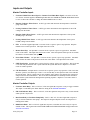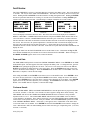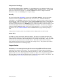
1
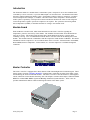
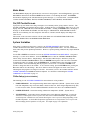
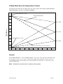
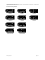
pCO2 CONTROLLER
USER MANUAL
CONTROLLER FOR “Turbostack”
WATER-COOLED CHILLER
for Version – MCTS_C00
Introduction
The Turbostack chiller is a modular water-cooled chiller system, composed of one or more modules and is
controlled by a master controller, to provide chilled liquid to an external circuit. The modules interconnect
through a common chilled water header system. Each module contains a Turbocor compressor, a stainless
steel, brazed plate heat exchanger, a condenser, and other related control components. Each Turbostack
chiller system is operated by a microprocessor based controller that monitors the status of each refrigerant
circuit and provides a signal to operate the compressors as required. The system uses the leaving chilled
water temperature (LCHWT) to determine the need for cooling to the external circuit.
Module Board
Each module has a module board, which sends information to the master controller regarding the
temperatures, pressures, and activity of the module. The feedback from the module board determines the
status of its circuits. The module board performs safety checks and alerts the master controller when
something is wrong. Loss of communication with the master controller results in the shutting down of the
module. The module board also communicates with the compressor in that module via Modbus. This allows
information from the compressor to be accessible from the master controller. Information like Actual RPM,
Desired RPM, Inverter Temperature, Critical Alarms, etc. from the compressor is available through this
connection.
Master Controller
The master controller is equipped with a 4x20 character LCD with backlight and a six button keypad. These
aid the operator in setting SYSTEM VARIABLES, checking faults, monitoring the status of the chiller system,
and monitoring the status of individual modules. The master controller is also the interface to field supplied
remote connections such as Remote Start/Stop, flow switch inputs, customer alarm outputs, CHILL WATER
RESET or LOAD LIMIT RESET signals and Building Automation Systems Interface. There is also an
optional communication link for remote monitoring and control of the chiller system.
PC02_UM_C00
Page 2
Master Controller Keys
The UP arrow button is used to go back to the previous category on the screen or to increase the value
of a digit in a numeric variable field.
The DOWN arrow button is used to advance to the next category on the screen or to decrease the
value of a digit in a numeric variable field.
The ENTER button is used to make a selection from any of the menu screens in the program. It is
also used to enter and exit edit mode while in the SYSTEM VARIABLES screens.
The ALARM button is the menu for current system or module faults. When the backlight is red, it
indicates that a fault has occurred.
Prg
The PROGRAM button goes to the MAIN MENU from any screen in the program.
Esc
The ESCAPE button goes to the previous screen or the status screen, if you are at the top of the
MAIN MENU.
TURBOSTACK
by Multistack
Controller Setup
On each controller, master or module, there is a set of 6 DIP switches. These switches define the network of
the chiller system and identify each module in the system. The DIP switches are set in binary code
addressing, where the first slot is a value of 1, the second is a value of 2, the third is a value of 4, the forth is
a value of 8, the fifth is a value of 16, and the sixth is a value of 32. The following DIP switch would give
an address of 30 to its controller. (The black square is the switch position.)
= 30
Switches
ON
2
3
4
5
Value
=
=
=
=
2
4
8
16
30
The following are the addressing parameters for setting up a Turbostack chiller network:
Turbostack Modules – 1 thru 8
Master Controller – 30
Remote LCD Display – 32
In setting up the network, the master controller must have an address of 30. The first module would be 1,
the next 2 and so on. For more help in DIP switch settings, see Appendix A on page 18.
PC02_UM_C00
Page 3
Main Menu
The MAIN MENU displays the options the user can access in the program. Press the Prg button to get to the
MAIN MENU and then use the UP and DOWN arrow buttons to scroll through the menu. The ENTER
button allows displaying of the sub-menu that the greater than sign (>) is located beside. The MAIN MENU
contains ON/OFF CONTROL, STATUS, SYSTEM VARIABLES, FAULT REVIEW, and SECURITY.
On/Off Control Screen
Upon power up, the initial screen will go through a 12 second delay before giving control to the user. The
ON/OFF CONTROL screen will be the next screen. It allows the user to command the chiller on or off. The
display will read ‘CHILLER OFF, PUSH ENTER TO START’. Pushing the ENTER button, will display a
message of ’30 SECONDS TO START!’ and will change to ‘CHILLER ON, PUSH ENTER TO STOP’.
After the 30 second delay, the first compressor will turn on, if needed, and the display will change to the
status screen.
The last line of the screen also can show critical system faults such as WAITING FOR CHW FLOW,
REMOTE SRART/STOP, and POWER PHASE MONITOR.
System Variables
Once power is connected to the master controller, the SYSTEM VARIABLES can be accessed. These
variables determine how the chiller system will run and are assigned default values. For most installations,
these values will provide optimum performance. However, special operating conditions may require different
settings.
Use the UP or DOWN arrow buttons to locate the SYSTEM VARIABLES in the MAIN MENU. The greater
than sign (>) is the cursor indicator. Press the ENTER button to enter the SYSTEM VARIABLES MENU.
Chiller Setup, Customer Resets, Temp Readings, Time and Date, BAS Interface, and Factory Setup are
located in the SYSTEM VARIABLES MENU. Press the ENTER button again to enter one of the sub-menus.
To change the value of a variable, press the ENTER button. A blinking block cursor will appear in that
system variables’ value field indicating that the program is in edit mode. Use the UP or DOWN arrow
buttons to change the value of the variable. To save the new setting, press the ENTER button, pressing the
Esc button will not save the change. The cursor will move back to the upper left corner of the screen
indicating that the program is no longer in edit mode. An asterisk (*) next to the variables indicates that the
SYSTEM VARIABLES are locked and cannot be adjusted. For assistance on unlocking the SYSTEM
VARIABLES, see SECURITY on page 15.
Chiller Setup (System Variables)
The following is a list of SYSTEM VARIABLES for the mechanical cooling modules:
1. UPPER SETPOINT: The designed entering chilled water temperature (ECHW – System sensor) at full
load. The temperature drop across this chiller is based on flow rate. If the design temperature drop (∆T)
is 10°F across the chiller, then the UPPER SETPOINT should be 10°F above the LOWER SETPOINT.
2. LOWER SETPOINT: The desired leaving chilled water temperature (LCHW – System sensor).
3. VSP SETPOINT: A percentage used to determine the no load chill water temperature. Leaving the
VSP at 0% would keep the control setpoint at the value of the LOWER SETPOINT. Raising the VSP
would incorporate a chilled water reset scheme allowing the control setpoint to change depending on the
ECHW Temperature. As the ECHW Temperature approaches the no load point the control setpoint will
shift accordingly until it equals the no load point. See Graph on page 7 for explanation.
PC02_UM_C00
Page 4
4. OFFSET: This value is not a selectable value; it is built into the program. The offset is figured in the
program by subtracting the LOWER SETPOINT from the UPPER SETPOINT and then dividing the
value by the number of modules. (Max is 5°) ((Upper – Lower) ÷ Modules) This value is used in starting
compressors. The LCHW Temperature has to be at or above the LOWER SETPOINT plus the OFFSET
to bring a compressor on.
5. LOAD LIMIT: A percentage used to limit the maximum system load. If this variable is set to 75% on
a 4 compressor chiller, then only 3 of the compressors would be available to run at any given time.
6. CAPACITY LIMIT: A percentage used to limit the maximum voltage sent to a compressor at any
given time. If this variable is set to 70%, then 7 volts is the maximum signal that can be sent to any of
the Turbocor compressors in the chiller system.
7. T-DIFF (Time Difference): The minimum time in seconds between increases in voltage to a compressor
on initial ramp up. This time should be set to the loop time of the chiller. The loop time is the time it
takes for the water to make one pass through the entire CHW loop of the building.
8. FAIL INDIC (Failure Indicator): A percentage value which provides for an output signal whenever
compressors of the indicated value have failed. A 0% setting will give an output signal after any failure
within the system.
9. LEAD COMP.: Determines which compressor is the first on. The first compressor off is the
compressor that has run the longest in that particular cycle.
10. NUM OF MODULES: This is the number of mechanical cooling modules that are in the chiller system.
11. HP CUTOUT: The point where a high pressure fault occurs based on the high pressure transducer,
measured in psig. Note: Each module also has a mechanical high pressure switch with a manual reset.
12. FLUSH TIME: The time at which the DDRS-210A is energized.
13. FLUSH DURATION: The time in seconds telling how long the DDRS-210A is energized.
14. INDEXING: The indexing can either be ON or OFF. If ON, the lead compressor advances by one
every 24 hours at midnight. If OFF, the LEAD COMPRESSOR stays the same and will have the most
runtime.
PC02_UM_C00
Page 5
Standard Application
Program Version Format
MCTS_C00
System Variable Ranges & Default Settings
Mechanical Cooling
The following table defines all of the SYSTEM VARIABLE ranges and default values for mechanical cooling
modules with the standard program.
System Variable
UPPER SETPOINT
LOWER SETPOINT
VSP VALUE
LOAD LIMIT
T-DIFF
FAIL INDIC
LEAD COMP.
NUM OF MODULES
HP CUTOUT
FLUSH TIME
FLUSH DURATION
INDEXING
Range
45°F to 80°F
40°F to 70°F
0% to 80%
0% to 100%
15 to 200 sec
0% to 90%
1 to 8
1 to 8
190 to 270 psig
0 to 23 hrs and 0 to 59 min
0 to 60 sec
OFF or ON
Default Value
55°F
45°F
0%
100%
90 sec
0%
1
1
200
12:00
20 sec
ON
Standard Module Cutouts and Reset Points
Low Suction Temp
Low Leaving CHW
Critical LCHW Temp
Low Pressure
High Pressure
PC02_UM_C00
Cutout → 25°F
Cutout → 36°F
Cutout → 34°F
Cutout → 15 psig
Cutout → HP Cutout Value
Reset @ 30°F
Reset @ 40°F
Reset @ 40°F
Reset @ 20 psig
Reset below 175 psig
Page 6
Chilled Water Reset for Temperature Control
The following chart defines how the chilled water reset scheme operates when utilizing UPPER SETPOINT,
LOWER SETPOINT, and VSP in the SYSTEM VARIABLES.
UPPER SETPOINT = 55.0
55
ECHW SYSTEM TEMP
54
53
VSP = 80%
52
51
T
E
M
P
(°F)
50
VSP = 50%
49
48
LOWER SETPOINT = 45.0
47
VSP = 20%
46
LCHW SYSTEM TEMP (Control Setpoint)
45
90
80
70
60
50
40
30
20
10
0
% OF LOAD
Example:
If the UPPER SETPOINT = 55°F; LOWER SETPOINT = 45°F; VSP = 50%; then the no load point would
be 50°F. ([upper – lower] * vsp ÷ 100 + lower = no load) In this example, if the ECHWT is at or above 55°F (upper
setpoint) then the control setpoint would be 45°F. If the ECHWT is at or below 50°F (no load) then the control
setpoint would be 50°F.
Note: VSP must be set at 0% to have a constant control setpoint.
PC02_UM_C00
Page 7
Master Controller Status Screens
System Screens
The main status screen displays information about the chiller system.
1. CAPACITY: A percentage of the chiller that is operating. It is calculated by taking the volts out of
each compressor multiplied by the number of compressors running compared to the number of modules
expressed as a percentage from 0 to 100. (([volts out added] * 10 ) * (compressors on ÷ # of modules)) An asterisk (*)
displayed next to capacity indicates that it is being controlled by an external source, either LOAD LIMIT
or CHILL WATER RESET.
2. DELAY: A time in seconds between voltage increases or compressor starts. A compressor should only
turn on or ramp to a new voltage if the delay time counter is at zero. This is determined by the
mechanical cooling module’s system variable T-DIFF.
3. FAULTS: A value showing how many current faults are in the chiller system.
4. ECHW: The Entering Chilled Water temperature to the chiller.
5. LCHW: The Leaving Chilled Water temperature from the chiller.
6. ECW: The Entering Condenser Water temperature to the chiller.
7. LCW: The Leaving Condenser Water temperature from the chiller.
Press the DOWN arrow button once to display the next main status screen with system information.
1. CONTROL SETPT: The LCHW Temperature that the chiller is trying to maintain.
2. LEAD COMP: The compressor shown is the first on. The compressor that has the most run time in the
cycle will be the first off.
3. LOAD LIMIT: A value to limit the max number of compressors available to run expressed in a
percentage from 0 to 100. An asterisk (*) indicates the external LOAD LIMIT RESET signal is enabled.
4. CHW OFFSET: Shows the value of the customer CHW RESET signal from 0 to 10°F. This value is
added to the UPPER and LOWER SETPOINTS. An asterisk (*) indicates the external CHW RESET
signal is enabled.
Mechanical Cooling Screens
Press the DOWN arrow button again to display information for the first mechanical cooling module. The
following information is available:
1. LCHW: The Leaving Chilled Water temperature in the module, measured when leaving the evaporator
coil.
2. SUCT: The Suction temperature in the module, measured on the compressor suction line.
3. HP: The High Pressure reading in psig based on the transducer in the module.
4. LP: The Low Pressure reading in psig based on the transducer in the module.
5. Status Line: The status line of the module can be the mode in which the module is in or it can be what
the current fault is on that module.
PC02_UM_C00
Page 8
Press the ENTER button a third time to display screen #2 for the first module.
1. RUN TIME: This displays the total number of hours that the compressor has run. To reset the run
hours, press and hold the ALARM and DOWN arrow buttons simultaneously on the screen of the
module whose hours need to be reset. The SYSTEM VARIABLES must be unlocked to clear
compressor run hours.
2. MTR SPEED: The speed the Turbocor compressor in RPM’s measured from a 0 to 3.9 volt signal sent
from the Turbocor compressor that equals 0 to 48,000 RPM.
3. VOLTS OUT: The 0-10V DC signal being sent to the Turbocor compressor from the master controller.
This signal will increase or decrease the shaft speed of the compressor.
The information on the next three screens is coming from the Turbocor compressor via a Modbus connection.
The chiller will operate properly without this connection. If all zeros are displayed, then the compressor is
not online or the connection is open.
Press the DOWN arrow button to display screen #3 for Compressor #1 Info – Alarms.
1. NON-CRIT: Active non-critical alarms from the Turbocor compressor. The non-critical alarms will
allow the compressor to continue operation.
2. CRITICAL: Active critical alarms from the Turbocor compressor. The critical alarms will not allow
the compressor to continue operation.
Press the DOWN arrow button to display screen #4 for Compressor #1.
1. ACT RPM: The actual shaft speed of the compressor.
2. DES RPM: The commanding shaft speed of the compressor. This will always be higher than the actual
shaft speed.
3. IGV %: The position of the Inlet Guide Vane expressed as a percentage from 0 to 110 (slightly beyond
fully open).
4. INVERTER TEMP: The inverter temperature as measured by the thermistor mounted under the IGBT
inverter.
Press the DOWN arrow button to display screen #5 for Compressor #1.
1. VOLTS: The calculated three phase mains voltage.
2. AMPS: The calculated three phase mains current.
3. DEMAND: The demand input to the compressor expressed as a percentage from 0 to 100. The
operating speed is directly related to the demand input.
PC02_UM_C00
Page 9
Inputs and Outputs
Master Controller Inputs
1. Customer Chilled Water Reset Signal or Customer Load Limit Reset Signal: A 0-10Volt, 0-20 mA,
or 4-20 mA, customer supplied, external signal that shifts the UPPER and LOWER SETPOINTS from 0
to 10°F or allows the customer to change the LOAD LIMIT from 0 to 100%.
2. Entering Condenser Water Sensor: A NTC type sensor that measures the temperature of the ECW
going to the chiller.
3. Leaving Condenser Water Sensor: A NTC type sensor that measures the temperature of the LCW
coming from the chiller.
4. Entering Chilled Water Sensor: A NTC type sensor that measures the temperature of the system
ECHW going to the chiller.
5. Leaving Chilled Water Sensor: A NTC type sensor that measures the temperature of the system
LCHW coming from the chiller.
6. EX1: A customer supplied input that is a closed circuit to operate; open to stop operation. Requires
manual reset to resume operation. This input will create a fault.
7. Remote Start/Stop: An input that is a closed circuit to operate; open to stop operation. Automatic
restart of the chiller. This input does NOT create a fault. After this input has been open for 90 seconds,
the contactor for the modules will open.
8. Power Phase Monitor: An input that is a closed circuit to operate; open to stop operation. Automatic
restart returns the chiller to the previous on/off state of the chiller. This input will create a fault.
9. CHW Flow Switch: An input that is a closed circuit to operate; open to stop operation. This circuit has
a 4 second delay between the time it opens and when the system shuts down. Requires a reset and a
restart to resume operation.
10. CW Flow Switch: An input that is a closed circuit to operate; open to stop operation. This circuit will
allow the system to start when open. There is a 10 second delay on start-up before this circuit will shut
the system down. This is to allow time for the condenser water pump to start with the first compressor
and provide water flow stabilization. This circuit has an additional 4 second delay between the time it
opens and the system shuts down during normal operating sequence. Requires a reset and a restart to
resume operation.
Master Controller Outputs
1. Customer Alarm Relay: This is a 24V AC, 5VA max signal that can power a relay to trigger an alarm.
The output is controlled by the failure indicator setting in the SYSTEM VARIABLES.
2. Full Load Indicator Relay: This is a 24V AC, 5VA max signal that can power a relay to show that the
chiller system is at full load.
3. Run Status Relay or Condenser Pump Relay: This is a 24V AC, 5VA max signal that can power a
relay to start the condenser water pump. This output is energized anytime at least one compressor is
running in the chiller.
4. DDRS-210A Flush: This is a 24V AC signal that can power a solenoid valve once a day for a preset
amount of time. This signal works with FLUSH TIME and FLUSH DURATION settings found in the
SYSTEM VARIABLES.
PC02_UM_C00
Page 10
Module Board Inputs
1. High Pressure Transducer: A 4-20 mA input sensor that measures the high side pressure of the
refrigerant in each module.
2. Low Pressure Transducer: A 4-20 mA input sensor that measures the low side pressure of the
refrigerant in each module.
3. Motor Speed: A 0-3.9V AC signal from the Turbocor compressor to calculate the speed that the shaft
of the Turbocor compressor is rotating. Motor Speed is measured in RPM’s.
4. Suction Sensor: A NTC type sensor that measures the temperature of the suction line.
5. Leaving Chilled Water Sensor: A NTC type sensor that measures the temperature of the LCHW in the
module.
6. Compressor Status: A compressor fault occurs when the status signal from the Turbocor compressor is
absent.
7. Circuit Status: An input that monitors the control circuit of each compressor for abnormal operating
conditions.
8. High Pressure Switch: Input of the mechanical switch for the high side pressure of the refrigerant
circuit.
9. Low Pressure Switch: Input of the mechanical switch for the low side pressure of the refrigerant
circuit.
Module Board Outputs
1. Compressor Speed Control: This is 0-10V DC signal that tells the compressor the desired speed that
the shaft should be rotating.
2. Liquid Line Solenoid Valve: A 24V output to energize the liquid line solenoid valve.
3. Compressor Contactor: A 24V output that energizes the contactor to give power to the control boards
of the Turbocor compressor.
4. Compressor Start Signal: A 24V output to start the compressors. The compressor start signal is
connected to the interlock of the Turbocor compressor. When the signal is not available, the compressor
will ramp down to 0 RPM and delevitate.
PC02_UM_C00
Page 11
Faults
If a fault has occurred, the ALARM button will illuminate. To view the current fault(s), press the ALARM
button. Use the UP and DOWN arrow and ENTER buttons to view and clear the fault(s). If the fault
returns, then it will need to be reset elsewhere first.
System Faults
If any of the following faults occur, all compressors in the system will be turned off.
1. EX1: Customer Input – EX1 requires a reset and restart command at the master controller.
2. Remote Start/Stop: Customer Input – This is NOT a fault. This circuit operates like an on/off switch.
If closed, the chiller is on. If open, the chiller is disabled and the compressors will not run.
3. Power Phase Monitor: When the Power Phase Monitor Input opens, the chiller is disabled until the
input is closed again. There is no reset required at the master controller. Automatic restart returns the
chiller to the previous on/off state of the chiller.
4. CW Flow: This alerts the master controller of NO FLOW on the condenser side of the chiller and
disables all modules. This fault requires a manual reset and a restart at the master controller.
5. CHW Flow: This alerts the master controller of NO FLOW on the evaporator side of the chiller and
disables all modules in the chiller. If the flow switch opens and the chiller has not been commanded ON,
a warning will appear at the bottom of the start/stop screen, however, no fault will occur. This fault
requires a manual reset and restart at the master controller.
6. LOCHW Temp: Low Leaving Chilled Water temperature. If the system LCHW falls below 36°F, all
compressors will turn off. The water temperature must rise to 40°F before the fault can change from
current to reset. This requires a manual reset and restart at the master controller.
7. Critical LCHW Temp: Critical Low Leaving Chilled Water temperature. If the system LCHW falls
below 34°F, the contactor to the compressor will open. This will cut the compressors off immediately.
The water temperature must rise to 40°F before the fault can change from current to reset. This requires
a manual reset and restart at the master controller.
8. ECHW Sensor Failure: The sensor for the system ECHW has either opened or shorted to the master
controller. This fault requires resetting at the master controller.
9. LCHW Sensor Failure: The sensor for the system LCHW has either opened or shorted to the master
controller. This fault requires resetting at the master controller.
10. ECW Sensor Failure: The sensor for the system ECW has either opened or shorted to the master
controller. This fault does not effect the operation of the chiller.
11. LCW Sensor Failure: The sensor for the system LCW has either opened or shorted to the master
controller. This fault does not effect the operation of the chiller.
PC02_UM_C00
Page 12
Mechanical Cooling Module Faults
The following faults will only affect the module that they are associated with.
1. High Pressure: High Pressure Cutout. This high pressure fault can come from either the transducer
reading or the HP switch being tripped. When the HP transducer reading reaches the value of the HP
CUTOUT the alarm goes off, shutting down that module. The fault can be reset at the master controller
after the high side pressure drops below 175 psig. If the High Pressure switch trips then, it requires
resetting at the module HP switch and the master controller to resume operation. The fault will remain
current until the HP switch is manually reset and the pressure is below 175 psig.
2. HP Sensor Failure: The High Pressure Transducer has either opened or shorted to the master
controller. This fault requires resetting at the master controller.
3. Low Pressure: Low Pressure Cutout. This low pressure fault can come from either the transducer
reading or the LP switch being tripped. When the LP transducer reading reaches the value of the LP
CUTOUT the alarm goes off, shutting down that module. The fault can be reset at the master controller
after the low side pressure rises above 20 psig. If the Low Pressure switch trips then, it requires
resetting at the module LP switch and the master controller to resume operation. The fault will remain
current until the LP switch is manually reset and the pressure is above 20 psig.
4. LP Sensor Failure: The Low Pressure Transducer has either opened or shorted to the master controller.
This fault requires resetting at the master controller.
5. Circuit Fault: A CIRCUIT FAULT will occur if the compressor contactor is not operating normally.
Four conditions could potentially create a CIRCUIT FAULT. One would be, if the program signals for
a contactor to be closed and it does not close within 5 seconds. Once the contactor has been closed for 5
seconds, if the contactor ever opens for 1 second while under normal operating conditions (indicating a
chattering contactor), a fault will occur. The third condition would be if the program turns a contactor
off and the contactor remains closed for an additional 10 seconds, this fault would occur (indicating a
welded contactor).
6. LOSUCT: Low Suction Temperature: This is measured by the module suction sensor and would affect
the entire module. If during operation this temperature should drop below 25°F, the module’s
compressor will shut down. This requires resetting at the master controller, but only after the
temperature has risen above 30°F. The system has to be on for this fault to occur.
7. SUCT SENSOR FAILURE: Suction Sensor Failure. This would occur if the suction line sensor opened
or shorted to the module board. This fault requires resetting at the master controller.
8. LOCHW TEMP: Low Leaving Chilled Water Temperature: This is measured by the module LCHW
temperature sensor. In a standard application if the temperature falls below 36°F, the module’s
compressor will turn off. The temperature must rise to 40°F before the fault can be reset at the master
controller.
9. LCHW SENSOR FAILURE: Leaving Chilled Water Sensor Failure: This would occur if the sensor
opened or shorted to the module board. This fault requires resetting at the master controller.
10. RPM DELAY: When a module is in an RPM delay, it means that compressor is not meeting the speed
requirement for the voltage signal that the master controller is sending to it. The delay will be active for
a period of ten minutes. If the volts out sent to the module increases, the timer will start over. As long
as the mtr speed of the compressor keeps up with volts out, then the RPM DELAY will not occur. If the
timer reaches the 10 minute limit, then the compressor will be disabled and will restart after its minimum
time off requirement is satisfied, if the compressor is needed.
11. COMM ERROR (pLan): Communication errors can occur when the master controller is not properly
communicating with the module boards in the chiller.
PC02_UM_C00
Page 13
12. Non-Critical Alarms: These alarms are from the Turbocor compressor and will be displayed on screen
#3 of the module where they occur. The non-critical alarms are warnings that the compressor is getting
close to a critical alarm. The non-critical alarms will not stop the operation of the compressor, but slow
down the motor. The following is a list of non-critical alarms that may be seen:
a.
b.
c.
d.
e.
f.
NO WARNINGS: No non-critical current alarms.
INVERT TEMP: High Inverter Temperature
DCHRG TEMP: High Discharge Temperature at the compressor flange.
LOW PRESS: Low Pressure at the compressor flange.
HIGH PRESS: High Pressure at the compressor flange.
3 PH CRNT: 3 Phase Over-Current - Excessive system load usually due to the compressor
pumping liquid. This can be a result from low voltage.
g. CAVITY TEMP: Shaft Cavity Temperature – Insufficient motor cooling.
h. TEMP SENSOR:
i. COMP RATIO: Total Compression Ratio –
j. SCR TEMP: SCR Temperature – Increased temperature of the AC to DC voltage rectifier.
13. Critical Alarms: These alarms are from the Turbocor Compressor and will be displayed on screen #3 of
the module and in the fault review when they occur. The critical alarms have exceeded the compressor’s
alarm setting and will stop the operation of the compressor. The following is a list of critical alarms that
may be seen:
a.
b.
c.
d.
e.
NO WARNINGS: No non-critical current alarms.
INVERT TEMP: High Inverter Temperature
DCHRG TEMP: High Discharge Temperature at the compressor flange.
LOW PRESS: Low Pressure at the compressor flange.
HIGH PRESS: High Pressure at the compressor flange. Note: A High Pressure alarm will
lock out the compressor. The compressor will have to be powered down manually.
f. 3 PH CRNT: 3 Phase Over-Current - Excessive system load usually due to the compressor
pumping liquid. This can be a result from low voltage. Note: A 3 Phase Over-Current alarm
will lock out the compressor. The compressor will have to be powered down manually.
g. CAVITY TEMP: Shaft Cavity Temperature – Insufficient motor cooling.
h. TEMP SENSOR:
i. COMP RATIO: Total Compression Ratio –
j. BEARING MTR: Bearing Motor (BMC) – Front or Rear radial displacement of the shaft.
k. SCR TEMP: SCR Temperature – Increased temperature of the AC to DC high voltage
rectifier.
l. SYS LOCK OUT: System Lock Out – If any combination of the alarms listed below occurs
more than 3 times within 30 minutes, a System Lock Out occurs:
i. Inverter Temperature Alarm
ii. Cavity Temperature Alarm
iii. SCR Temperature Alarm
PC02_UM_C00
Page 14
Fault Review
The FAULT REVIEW is a history of the faults that have occurred in the chiller system. The review holds up
to 25 faults. The review can be found in the MAIN MENU. The faults are in order by the most recent to the
oldest. Pushing the UP and DOWN arrow buttons allows scrolling through the faults. Pushing the ENTER
button on a particular fault allows for viewing of a second screen of information. Pushing ENTER again
returns to the first screen of the fault. The following is a sample of what the two screens contain.
FAULT 01
CURRENT
COMMUNICATION ERROR
MOD1
9/17 12:35
PRESS ENTER FOR MORE
FAULT 01
*SYS INFO*
ECHW 00.0
ECW 000.0
LCHW 00.0
LCW 000.0
PRESS ENTER FOR MORE
FAULT 01
* MOD INFO *
LCHW 00.0
HP = 000
SUCT 00.0
LP = 000
Screen #1
Screen #2
Screen #3
Screen one displays information about the fault. The status of the fault will be displayed as CURRENT,
RESET, or RECORD. CURRENT means that the fault is still present, RESET means that the fault can be
reset at the master controller, and RECORD means that the fault is part of the history for future reference.
The date and time of the fault, the fault that occurred and where the fault occurred are also displayed on the
first screen. On screen two, the system temperatures at the time the fault occurred will be displayed on the
left side of the screen and are starred with an asterisk (*). On the right side of the screen is module
information that was current at the time of the fault. If the fault is a system fault the module information will
display all zeros.
Clearing the faults from the FAULT REVIEW removes all the faults at once. Hold down the Prg and UP
arrow buttons simultaneously for all faults to be removed from the FAULT REVIEW. When a message of
NO MORE ALARMS appears on the screen, release the buttons.
Time and Date
The TIME AND DATE option is located in the SYSTEM VARIABLES’ MENU. Press ENTER on the TIME
AND DATE option. The time appears first and is displayed in military time. To change the time, press the
ENTER button, putting the program into edit mode. The cursor is now in the hour field, use the UP and
DOWN arrow buttons to change the hour to the correct time. Press the ENTER button again to move the
cursor to the minute field to change it. Press the ENTER button one more time to set the TIME. Press the
Esc button, at anytime, to abort the time change.
After setting the TIME, use the DOWN arrow button to move to the DATE screen. Press ENTER to move
the cursor into the month field. Using the UP and DOWN arrow buttons, change the value to the current
month. Press ENTER again to move the cursor to the day field, adjust the day accordingly. Press ENTER
again to move to the year field, adjust the year accordingly. Press ENTER one more time to accept the
DATE. Press the Esc button, at anytime, to abort the date change.
Customer Resets
CHILL WATER RESET (CHW) and LOAD LIMIT RESET are external inputs that are program selectable
as 0-10Volt, 0-20 mA, or 4-20 mA. The customer can send a signal to change these values remotely. The
CHW RESET will increase the UPPER and LOWER SETPOINTS in the mechanical cooling modules
anywhere from 0 to 10 °F. The LOAD LIMIT RESET will allow the LOAD LIMIT of the mechanical
cooling modules to be changed. There will be an asterisk (*) by the CHW OFFSET and the LOAD LIMIT
values on the second system status screen, if they are enabled. The CUSTOMER RESET options are located
in the SYSTEM VARIABLES’ MENU. An asterisk (*) also appears next to CAPACITY on the main status
screen when either reset is enabled. Press ENTER and use the UP and DOWN arrow buttons to change the
value. Both default to OFF, but when enabling the user must select the type of input being used. (0-10 Volt,
0-20 mA, or 4-20 mA)
PC02_UM_C00
Page 15
Temperature Readings
The temperature readings default to Fahrenheit (°F). The readings may be set to display in Celsius (°C), by
going to the SYSTEM VARIABLES’ MENU. Press ENTER on TEMP. READINGS option. Press ENTER
again to move the cursor into the field. Use the UP or DOWN arrow button to change the field from
Fahrenheit to Celsius. Press ENTER again to accept the change.
Security
The security option in the MAIN MENU is used to lock the SYSTEM VARIABLES. The first screen tells
whether the variables are locked or unlocked. Initially the screen will say ‘SYSTEM VARIABLES
UNLOCKED’. Press ENTER to change the status of the security. The cursor will be on the first letter of
the password code. Enter a five letter password, using the UP and DOWN arrow buttons to change the letter
and press ENTER to move to the next letter. After entering the last letter, the next screen is to accept the
password or clear the password. Press ENTER again to set the password or Esc to clear the password. The
screen will then display the status of the SYSTEM VARIABLES as LOCKED. An asterisk (*) is displayed
within the SYSTEM VARIABLES’ MENU in place of the greater than sign (>) as a cursor for the menu. If
the asterisk is seen, the SYSTEM VARIABLES need to be unlocked before trying to make any changes to
them.
If the password is forgotten, please call your Multistack Service Representative at 608-786-3400.
Board LED’s
Five LED’s are present on each board, master and module. Two LED’s are located at the bottom of the
board, one yellow and one red. The yellow one indicates that the board is receiving power. The red one is
an alarm LED that would indicate that something maybe wrong with the board internally. Three more LED’s
are located at the top of the board next to the DIP switches. These LED’s indicate that the connection,
address definition and pLan (network of the modules) are working correctly. The green and yellow LED’s
should be lit for the network to be working properly.
Program Version
The program version is found by going to the Main Menu and pressing the PRG and UP arrow buttons
simultaneously. A screen will appear that displays the version of the program in the controllers and the
month and year the program was developed. The version will appear in a format similar to MCTS_B10.
When looking at the version, the forth position could vary between S, L, and B. The S stands for a Standard
application, the L for a Low Ambient application, and the B for a Brine or Low Temperature application.
This each of these programs may have different cutouts or temperature ranges available to the customer. The
standard application system variables and cutouts are located on page 6.
PC02_UM_C00
Page 16
BAS Interface
The master controller is capable of tying into a building automation system. Modbus and BACnet are the two
protocols that are currently available. First the BAS INTERFACE needs to be enabled. This is accomplished
by going to the SYSTEM VARIABLES Menu and changing the enable point, under BAS INTERFACE, to yes.
The enable defaults to no. This menu also has a variable to select which Protocol will be used. Select the
appropriate Protocol for the job. BACnet is the default for this variable.
Modbus
Modbus requires that a RS485 card is installed into the pCO2 Master Controller. This card plugs into the
serial port and communicates Modicon Modbus Protocol Rev. D. The Modbus protocol used is RTU type.
The configuration is multipoint for RS-485. The data communication is asynchronous serial, 8 data bits, 2
stop bits, and no parity across an EIA-485 two-wire half-duplex connection. The cable size recommended is
an AWG20/22 two-wire twisted shielded cable. The pin wiring is GND, RX+/TX+, RX-/TX- and is
stamped on the terminal connector. The customer can adjust the Baud Rate and the Network Number. These
settings are found in the SYSTEM VARIABLES Menu under BAS INTERFACE. The Baud Rate defaults to
9600 bps and can be adjusted to 1200, 2400, 4800, 9600, or 19200 bps. The Network Number is the same as
a slave address and defaults to 1. This number must be unique to the Modbus network. The range for the
Network Number is from 1-200. See the Turbocor Modbus Technical Manual for a table of Modbus
registers.
Figure 1 - RS485 Card
Figure 2 - pCO2 with RS485 Card
BACnet
BACnet requires that a pCO Web card is installed in to the pCO2 Master Controller. This card plugs into the
serial port and communicates BACnet over Ethernet (ISO8802-2 or 8802-3) or BACnet over TCP/IP (Addenda
A/Annex J). The recommended cable is shielded class 5, max 100mt. The Baud Rate is selectable and defaults
to 19200. See the Turbocor BACnet Technical Manual for a table of points and instructions on changing the IP
Addressing scheme.
Figure 3 – pCO Web Card
Figure 4 - pCO2 with pCO Web Card
PC02_UM_C00
Page 17
APPENDIX A
DIPSWTICH SETUP
PC02_UM_C00
Page 18
The following are the positions of the DIP switches to setup the network of Turbostacks. The black square
represents the location of the switch.
Mechanical Cooling Modules
Module 1
Module 4
Module 2
Module 5
Module 7
Module 8
Master Controller
Remote Display
PC02_UM_C00
Module 3
Module 6
Page 19
APPENDIX B
DEFINITION OF
INPUTS AND OUTPUTS
PC02_UM_C00
Page 20
TURBOCOR
MASTER CONTROL (UNIT WITH DISPLAY)
ANALOG INPUTS
B1
CHW RESET OR LOAD LIMIT RESET (selectable)
B2
ENTERING CONDENSER WATER SENSOR (ECW)
B3
LEAVING CONDENSER WATER SENSOR (LCW)
B4
ENTERING CHILL WATER SENSOR (ECHW)
B5
LEAVING CHILL WATER SENSOR (LCHW)
DIGITAL INPUTS
ID1 EX 1 INPUT
ID2 REMOTE START / STOP
ID3
ID4 POWER PHASE MONITOR
ID5 CHILL WATER FLOW SWITCH
ID6 CONDENSER WATER FLOW SWITCH
ID7
ID8
ANALOG OUTPUTS
Y1
Y2
Y3
Y4
DIGITAL OUTPUTS (RELAY TYPE)
NO1 CUSTOMER ALARM RELAY
NO2 FULL LOAD RELAY
NO3 RUN STATUS OR CONDENSER PUMP RELAY
NO4 DDRS
NO5
NO6
NO7
NO8
NC8
PC02_UM_C00
Page 21
TURBOCOR
MODULE BOARDS
ANALOG INPUTS
B1
HIGH PRESSURE TRANSDUCER (HP)
B2
LOW PRESSURE TRANSDUCER (LP)
B3
MOTOR SPEED INPUT (FROM THE COMPRESSOR)
B4
SUCTION SENSOR (SUCT)
B5
LEAVING CHILL WATER SENSOR (LCHW)
DIGITAL INPUTS
ID1 COMPRESSOR STATUS (FROM THE COMPRESSOR)
ID2 CIRCUIT STATUS (FROM THE CONTACTOR)
ID3 HIGH PRESSURE SWITCH (HP)
ID4 LOW PRESSURE SWITCH (LP)
ID5
ID6
ID7
ID8
ANALOG OUTPUTS
Y1
COMPRESSOR SPEED CONTROL (0-10Volt)
Y2
Y3
Y4
DIGITAL OUTPUTS (RELAY TYPE)
NO1 LIQUID LINE SOLENOID VALVE
NO2 COMPRESSOR CONTACTOR
NO3
NO4
NO5
NO6
NO7 COMPRESSOR START SIGNAL (INTERLOCK)
NO8
NC8
PC02_UM_C00
Page 22
APPENDIX C
REMOTE DISPLAY
PC02_UM_C00
Page 23
Remote Display Setup
If the remote display is not displaying the same information the master is, follow these steps to correct it.
First look on the back of the remote display, the DIP switches should be addressed to 32, which should be all
switches off except for switch number 6, which should be on. Hold down the 3 buttons in the lower right
corner of the remote display, UP and DOWN arrow buttons and the ENTER button. A screen will come up
with Terminal Adr: 32 and I/O Adr: 30. The I/O Adr: should be a value of 30, to point the remote display
at the master controller. Press ENTER, the next screen says Terminal config press ENTER to continue.
Press ENTER to go to the remote setup screen. This screen looks like the following illustration.
P: 30 Adr. Priv/Shared
Trm1: 32
Pr
Trm2: None -Trm3: None -- OK? NO
Figure 1
P: 1 Adr. Priv/Shared
Trm1: None -Trm2: None -Trm3: None -- OK? NO
Figure 2
The number after the P would be the address of the DIP switch on the board. For the remote display to
work properly, this screen should look exactly like Figure 1 for the master controller (30) only. Press the
ENTER button until NO is reached and change to YES. Every module, 1 – 14 should look like Figure 2.
Every module number in the network needs to be setup to look like Figure2. For each new module, this
requires starting from the beginning. To change the number of the I/O Adr, use the UP and DOWN arrow
buttons.
PC02_UM_C00
Page 24
APPENDIX D
PROGRAMMING KEY
&
PROGRAMMING
PC02_UM_C00
Page 25
PROGRAM KEY
The Program Key is an electronic card which allows transfer of the program from the key to the pCO2
controller and vice-versa. The Key contains a two position switch, a LED on the top of the key, and a
connector to place the key on the memory card to transfer the program. The following step by step directions
are for downloading a program.
DOWNLOADING A PROGRAM
Downloading a program is taking a program from the key and putting it on the pCO2 controller. Each
controller must have the new program installed for the chiller to perform properly. To download the
program to the controllers, a remote display and a program key are needed.
1.
2.
3.
4.
5.
6.
7.
8.
9.
10.
11.
Record all SYSTEM VARIABLES from the current program.
Command the chiller off.
Unplug the pLan connections from all controllers at the J11 port.
In the module to be programmed, turn off the power to the controller at CB3, the 2 amp, two pole
circuit breaker (see wiring diagram for further identification).
Set the dipswitches to off on the controller being programmed.
Remove the “Expansion Memory” cover with a small screwdriver.
Set the switch on the Program Key to the “key to pCO” position.
Insert the key connector onto the memory card inside the “Expansion Memory” port.
Connect the remote display to the J10 port. Prior to connecting the display, make sure the
dipswitches are in the off position on the remote display.
Press simultaneously the UP and DOWN arrow buttons located beside the ENTER button on the
remote display, while cycling the power on to the controller at CB3.
Check the color of the LED on the Program Key; it should be red at this time. If the LED is green,
cycle power off; carefully remove the Program Key and position the switch to the “key to pCO”
position.
Then repeat steps 9 through 12.
12. Continue holding the buttons until confirmation of copying the program appears on the display.
There should be 2 long beeps before the confirmation screen appears.
13. Release the buttons and confirm to copy the program by pressing the ENTER button.
14. The display will run through a series of numbers and letters and then return to a self test screen.
15. When the self test screen is reached, cycle the power off at CB3.
16. Remove the remote display from the J10 port.
17. Carefully remove the Program Key.
18. Replace the “Expansion Memory” port cover.
19. Return the dipswitches for that controller to their original positions.
20. Cycle the power on at CB3.
21. Repeat steps 5 through 21 for all remaining controllers.
22. After all controllers have been programmed, plug in the pLan connections of all controllers at the
J11 port.
23. Cycle the power off at CB3, of the master controller module only, for 5 seconds.
24. Cycle the power on at CB3.
25. While on the 12 second delay screen of the program, simultaneously press the PRG and UP arrow
buttons, and hold until the backlight dims, then release. Then simultaneously press the DOWN
arrow and ALARM buttons. This resets the program to all default values.
26. Reset the SYSTEM VARIABLES to the values recorded before downloading the new program.
27. The chiller is now ready to be commanded on again.
PC02_UM_C00
Page 26