1
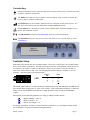
g. CAVITY TEMP: Shaft Cavity Temperature – Insufficient motor cooling.
h. TEMP SENSOR: Motor Winding
i. COMP RATIO: Total Compression Ratio – This fault will occur if the difference between the
discharge pressure and suction pressure is outside the operational envelope of the compressor.
j. SCR TEMP: SCR Temperature – Increased temperature of the AC to DC voltage rectifier.
9. Critical Alarms: These alarms are from the compressor and will be displayed on the compressor alarm
screen of the module and in the fault review when they occur. The critical alarms have exceeded the
compressor’s alarm setting and will stop the operation of the compressor. The following is a list of
critical alarms that may be seen:
a.
b.
c.
d.
e.
NO WARNINGS: No critical current alarms.
INVERT TEMP: High Inverter Temperature
DCHRG TEMP: High Discharge Temperature at the compressor flange.
LOW PRESS: Low Pressure at the compressor flange.
HIGH PRESS: High Pressure at the compressor flange. Note: A High Pressure alarm will
lock out the compressor. The compressor will have to be powered down manually. Power must
be cycled to the compressor (off for 3 minutes) to clear this alarm.
f. 3 PH CRNT: 3 Phase Over-Current - Excessive system load usually due to the compressor
pumping liquid. This can be a result from low voltage. Note: A 3 Phase Over-Current alarm
will lock out the compressor. Power must be cycled to the compressor (off for 3 minutes) to
clear this alarm.
g. CAVITY TEMP: Shaft Cavity Temperature – Insufficient motor cooling.
h. TEMP SENSOR: Motor Winding
i. COMP RATIO: Total Compression Ratio – This fault will occur if the difference between the
discharge pressure and suction pressure is outside the operational envelope of the compressor.
j. BEARING MTR: Bearing Motor (BMC) – Front or Rear radial displacement of the shaft.
k. SCR TEMP: SCR Temperature – Increased temperature of the AC to DC voltage rectifier.
l. SYS LOCK OUT: System Lock Out – If any combination of the alarms listed below occurs
more than 3 times within 30 minutes, a System Lock Out occurs:
i. Inverter Temperature Alarm
ii. Cavity Temperature Alarm
iii. SCR Temperature Alarm
Fault Review
The FAULT REVIEW is a history of the faults that have occurred in the chiller system. The review holds up
to 25 faults. The review can be found in the MAIN MENU. The faults are in order by the most recent to the
oldest. Pushing the UP and DOWN arrow buttons allows scrolling through the faults. Pushing the ENTER
button on a particular fault allows for viewing additional system information. Pushing ENTER again allows
for viewing additional module information. The following is a sample of what the three screens contain:
FAULT 01
CURRENT
COMMUNICATION ERROR
MOD1
9/17 12:35
PRESS ENTER FOR MORE
FAULT 01
*SYS INFO*
ECHW 00.0
ECW 000.0
LCHW 00.0
LCW 000.0
PRESS ENTER FOR MORE
FAULT 01
* MOD INFO *
LCHW 00.0
HP = 000
SUCT 00.0
LP = 000
Screen #1
Screen #2
Screen #3
Screen one displays information about the fault. The status of the fault will be displayed as CURRENT,
RESET, or RECORD. CURRENT means that the fault is still present, RESET means that the fault can be
reset at the master controller, and RECORD means that the fault is part of the history for future reference.
The date and time of the fault, the fault that occurred and where the fault occurred are also displayed on the
first screen. On screen two, the system temperatures at the time the fault occurred are displayed. On screen
MCTS_A01-SE
Page 15