1
Research Journal of Agricultural Science, 41 (1), 2009
- The Shape Wizard program helps transfer the required system parameters (Inlet
Lateral Flow Rate, Minimum Head Pressure) from the Emitters program to the SubMain
program.
- The Valves program calculates the valve friction loss according to the given
parameters.
- The Shifts program calculates the irrigation rate and number of shifts needed
according to the given parameters.
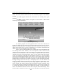
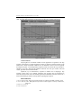
Figure 1. HydroCalc Irrigation Planning
The Emitters program is the first application which can be used in the frame of
HydroCalc software. There are 4 basic type of emitters which can be used: Drip Line, On line,
Sprinklers and Micro-Sprinklers. According to the previous selection the user can opt for a
specific emitter which can be a pressure compensated or a non pressure compensated. Each
emitter has its own set of nominal flow rate values available.
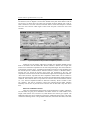
After the previous mentioned fields were completed, the program automatically fills
the following fields: “Inside Diameter”, “KD” and “Exponent”, values which cannot be
changes unless the change will be made in the database. The segment length is next field in
which the user must introduce a value. The end pressure represents the actual value for
calculation of pressure at the furthest emitter. There are some common values for this field:
around 10 m for drippers, around 20 m for mini-sprinklers, between 20 – 30 m for sprinklers
and around 2 m when using the flushing system. There are 2 more options which can be filled
before starting the computation, options which can also be used with their default values. The
Flushing field can be used if the user intends to calculate a system that includes and lateral
flushing. Flushing option will work only in subsequently will be used the “Emitter Line
Length” calculation method. The second option is about topography. Default value is 0%.
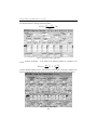
Topography field has 2 sub-fields: fixed slope and changing slope. Usually the slopes values
are not exceeding 10%. In many cases the slope is not uniform. The option “Changing” offers
to the user the possibility to determine the altitude along the line, from end line to submain, up
to 10 points each consisting of 2 cells: one for distance one for height. The line of distances is
used to load the distance from the end of the line to the point of the altitude change. These
distances may be unequal. The value of each cell is the net distance from the end of the line
422