1
Connections
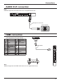
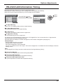
SERIAL Terminals connection
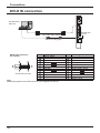
The SERIAL terminal is used when the Display is controlled by a computer.
1
2
6
COMPUTER
3
7
4
8
5
9
Pin layout for SERIAL Terminal
RS-232C Straight cable
(Female)
(Male)
D-sub 9p
Notes:
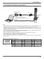
• Use the RS-232C straight cable to connect the computer to the Display.
• The computer shown is for example purposes only.
• Additional equipment and cables shown are not supplied with this set.
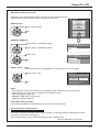
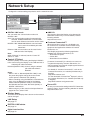
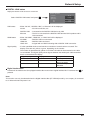
• When using serial control with this display, be sure to congure the “Control I/F Select” in the “Network Setup” menu.
When controlling the Display with RS232C terminal, select “RS-232C (Serial)”. When controlling with the RS232C
terminal of a DIGITAL LINK device, select “RS-232C(DIGITAL LINK)”. (see page 43)
The SERIAL terminal conforms to the RS-232C interface
specication, so that the Display can be controlled by a
computer which is connected to this terminal.
The computer will require software which allows the
sending and receiving of control data which satises
the conditions given below. Use a computer application
such as programming language software. Refer to the
documentation for the computer application for details.
Signal names for D-sub 9P connector
Pin No.
2
3
5
4 • 6
7
8
1 • 9
Communication parameters
Signal level
Synchronization method
Baud rate
Parity
Character length
Stop bit
Flow control
RS-232C compliant
Asynchronous
9600 bps
None
8 bits
1 bit
None
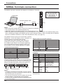
Basic format for control data
The transmission of control data from the computer starts with
a STX signal, followed by the command, the parameters, and
lastly an ETX signal in that order. If there are no parameters,
then the parameter signal does not need to be sent.
STX
C1 C2 C3
Start
(02h)
:
P1 P2 P3 P4 P5
End
(03h)
Notes:
• If multiple commands are transmitted, be sure to wait for
the response for the rst command to come from this unit
before sending the next command.
• If an incorrect command is sent by mistake, this unit will
send an “ER401” command back to the computer.
• Consult an Authorized Service Center for detail instructions
on command usage.
14
(Shorted in this set)
NC
These signal names are those of computer specications.
Command
Command
PON
POF
AVL
AMT
IMS
ETX
Colon
Parameter(s)
(1 - 5 bytes)
3-character
command (3 bytes)
Details
RXD
TXD
GND
Non use
DAM
Parameter
None
None
***
0
1
None
HM1
DV1
PC1
DL1
None
ZOOM
FULL
NORM
ZOM2
Control details
Power ON
Power OFF
Volume 000 - 100
Audio MUTE OFF
Audio MUTE ON
Input select (toggle)
HDMI input (HDMI)
DVI-D IN input (DVI)
PC IN input (PC)
DIGITAL LINK input
Screen mode select (toggle)
Zoom1
16:9
4:3
Zoom2
With the power off, this display responds to PON
command only.