1
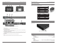
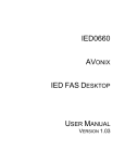
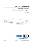
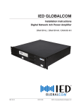
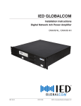
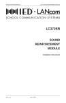
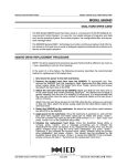
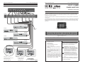
INSTALLATION INSTRUCTIONS
LC41PI / LC48MPI POWER INJECTORS
INSTALLATION INSTRUCTIONS
LC41PI / LC48MPI POWER INJECTORS
CONNECTION DIAGRAM
LC41PI / LC48MPI
POWER INJECTORS
Installation Instructions
ETHERNET SWITCH
LC48MPI
INTRODUCTION
The LC41PI and LC48MPI Power Injectors are an integral part of the LANcom SCS system. They provide operating
voltage and current for the LC372SR Classroom Sound Reinforcement Module, LC331IC Integrated Communications
Module and other LANcom components.
The LC41PI 1-port power injector is a small power block that provides up to 1.35 amps of power for one LANcom SCS
endpoint device.
The LC48MPI 8-port power injector is a 1RU rack mount unit that provides power for up to eight LANcom SCS endpoints.
Each port can supply power to devices such as the LC372SR classroom sound reinforcement module with its 30 watt
amplifier. Every port is fuse protected and all ports can provide up to 1.35 amps simultaneously. Includes eight 3’ CAT6
patch cables
LC372SR
CALL SWITCHES
REMOTE MIC
ETHERNET/
IED MIDSPAN
AUX
INPUT
PUTS
NO NC C NO
Model# LANcom LC372SR
LC372SR
AUX
INPUT
ETHERNET/
IED MIDSPAN
HANDSET
INTERFACE
AUX AUDIO INPUT
+ - S + - S
SPKR
LINE
OUT
OUT
MUTE POWER
+ - S + - M
V
Figure 1 - LC41PI Front View
Category 5e
Cable
IR RECEIVER INPUTS
CALL SWITCHES
REMOTE MIC
FORM C RELAY OUTPUTS
NC C NO NC C NO NC C NO NC C NO
2SR
LC372SR
IR RECEIVER INPUTS
ETHERNET/
IED MIDSPAN
HANDSET
INTERFACE
SPKR
OUT
AUX AUDIO INPUT
LINE
OUT
MUTE POWER
FORM C RELAY OUTPUTS
Figure 2 - LC48MPI Front View
LC372SR
IMPORTANT SAFETY INSTRUCTIONS
IR RECEIVER INPUTS
CALL SWITCHES
REMOTE MIC
AUX
INPUT
HANDSET
INTERFACE
2SR
LC372SR
1.
2.
3.
4.
5.
6.
7.
IR RECEIVER INPUTS
ETHERNET/
HANDSET
8.
J2
J3
9.
J9
J10
J6
S1
J6
J7
J2
J3
J6
J2
J3
S1
J7
S1
J8
LC331IC-C
Innovative Electronic Designs, LLC
9701 Taylorsville Road
Louisville, KY 40299, USA
REV: 04-11
LC331IC-W
10.
J9
J10
J9
J10
J8
J7
J8
LC331IC-W
Read these instructions.
Keep these instructions.
Heed all warnings.
Follow all instructions.
Do not use this apparatus near water.
Clean only with dry cloth.
Install in accordance with the manufacturer’s instructions.
Do not install near any heat sources such as radiators, heat registers, stoves, or other apparatus
(including amplifiers) that produce heat.
Only use attachments/accessories specified by the
manufacturer.
Refer all servicing to qualified service personnel.
Servicing is required when the apparatus has been
damaged in any way, such as power-supply cord
or plug is damaged, liquid has been spilled or objects have fallen into the apparatus, the apparatus
has been exposed to rain or moisture, does not
operate normally, or has been dropped.
+1.502.267.7436 phone
+1.502.267.9070 fax
www.iedaudio.com
DOC: 1303B
©2011, Innovative Electronic Designs, LLC
REV: 04-11
SAFETY SYMBOLS
Labeling on products and the Installation Instructions &
User Manual may use safety related graphical symbols
as shown below to note safety requirements.
Lightning Bolt: The lightning flash with
arrowhead symbol, within an equilateral triangle,
WARNING symbol, is intended to alert the user to
the presence of un-insulated dangerous voltage
within the product’s enclosure that may be
sufficient in magnitude to constitute a risk of
electric shock to persons or domestic animals.
Exclamation Point: The exclamation point
within an equilateral triangle, CAUTION symbol,
is in-tended to alert the user to the presence of
important operating and maintenance (servicing)
instructions, or a hazard that can damage equipment.
Do not proceed beyond a WARNING or CAUTION notice
until you have understood the hazardous condition and
have taken appropriate steps.
DOC: 1303B
PAGE 1
LC41PI / LC48MPI POWER INJECTORS
INSTALLATION INSTRUCTIONS
LC41PI / LC48MPI POWER INJECTORS
RJ45 Connector Wiring
CONNECTIONS
4
INSTALLATION INSTRUCTIONS
2
3
Each pair of ports connects to either a network switch or a LANcom endpoint device using CAT5e or better structured
cable. Each connector should be wired as shown below.
1
Pin
1
2
3
4
5
6
7
8
Figure 3 - LC41PI Front and Rear Views
5
4
4
CAT5 Color Code
de
Orange /W
Orange
Green /W
Blue
Blue/W
Green
Brown /W
Brown
PIN 1
Table 1 - RJ45 Input (Data) Connector Wiring
Pin
1
2
3
4
5
6
7
8
3
3
Function
Data Rx +
Data RX –
Data TX +
Not Used
Not Used
Data TX –
Not Used
Not Used
2
Function
Data Rx +
Data RX –
Data TX +
+48V DC
+48V DC
Data TX –
–48V DC (Ground)
–48V DC (Ground)
CAT5 Color Code
Orange /W
Orange
Green /W
Blue
Blue/W
Green
Brown /W
Brown
Table 2 - RJ45 Output (Data / PWR) Connector Wiring
2
1
Fuse Replacement (LC48MPI Only)
If a fuse is blown, it can be replaced as shown in Figure 5. Use caution to ensure that the pins are properly aligned when
inserting a new fuse.
DATA/
PWR
DATA
Figure 4 - LC48MPI Front and Rear Views
1. Power Connector
This connector to attach a power cord to provide AC power to the device.
2. Input RJ45 (Data) Connector
This input RJ45 connector is used to connect to a network switch. This port connects to a non-powered network
switch and uses a connector wired as shown in Table 1.
Figure 5 - Fuse Replacement (LC48MPI)
3. Output RJ45 (Data / PWR) Connector
This output RJ45 connector is used to connect to a LANcom endpoint device that requires PoE for operation. This
port provides both data and +48V DC power to the device. The connector should be wired as shown in Table 2.
4. Indicator LED
This blue indicator LED indicates that power is present at the Data / PWR port.
Specifications
5. Fuse
This is a replaceable fuse that protects the output of each port from drawing too much current.
PAGE 2
DOC: 1303B
Electrical
Input Voltage ......................................................................................................... 85VAC – 264VAC, 50Hz – 60Hz
Output Voltage ............................................................................................................................................. 48VDC
Output Current (per port)............................................................................................................................... 1.35A
Fuse (LC48MPI per port) ................................................................................................................ 1.5A slow-blow
Mechanical
LC41PI
Dimensions .................................................3.5” W x 1.75” H x 6.375” D (88.9mm W x 44.5mm H x 161.9mm D)
LC48MPI
Dimensions (with rack ears) ......................19” W x 1.75” H x 10.53” D (482.3mm W x 44.5mm H x 267.5mm D)
Width (without rack ears) ........................................................................................................... 17.01” (431.8mm)
REV: 04-11
REV: 04-11
DOC: 1303B
PAGE 3