1
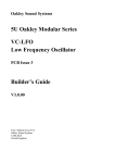
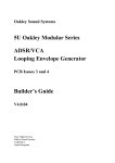
Oakley Sound Systems
5U Oakley Modular Series
Little-LFO
Low Frequency Oscillator
PCB Issue 6
Builder’s Guide
V6.1.1
Tony Allgood
Oakley Sound Systems
CARLISLE
United Kingdom
1
The suggested front panel for fitting three Little-LFO boards behind one 2U wide faceplate.
2
Introduction
This is the Project Builder's Guide for the issue 6 Little-LFO 5U module from Oakley Sound.
This document contains a basic introduction to the board, a description of the schematic, a full
parts list for the components needed to populate the boards, and help with the various
interconnections.
For the User Manual, which contains an overview of the operation of the unit, the history of
the various board issues and how to use the unit, please visit the main project webpage at:
http://www.oakleysound.com/lfo.htm
For general information regarding where to get parts and suggested part numbers please see
our useful Parts Guide at the project webpage or http://www.oakleysound.com/parts.pdf.
For general information on how to build our modules, including circuit board population,
mounting front panel components and making up board interconnects please see our generic
Construction Guide at the project webpage or http://www.oakleysound.com/construct.pdf.
3
The issue 6 Little-LFO PCB
The PCB is small and almost cute at just 64mm x 52mm in size. It uses double sided copper
traces and has through plated holes. It has solder mask both sides for easier soldering, and has
component legending on the top side for easier building.
I have provided space for the two control pots on the PCB. These can be mounted away from
the PCB, but they do form part of the mounting process, as no holes are provided on the PCB
for supporting the board. If you use the specified pots and brackets, the PCB can be held very
firmly to the front panel. The pot spacing is 1.625” and is the same as MOTM modular
synthesiser. The board is fully MOTM panel compatible if the board is fitted horizontally, ie. in
a 2U wide panel. I have included a suggested front panel layout at the back of this document.
The sixth issue of the Little-LFO board is pretty much unaltered from the fifth version with
one exception. The DG403 now has an additional 5V supply. This allows later versions of the
DG403 chips, namely ones made by Vishay, to sync with 5V gate signals.
The issue 6 Little-LFO board fully populated. The MTA156 header has been fitted to this one allowing it
to connect to the Oakley/MOTM and Fractional Rack modular systems. The pots used here are the ones
with a short 6mm knurled shaft.
4
Power supply requirements
The design requires plus and minus 15V supplies. The power supply should be adequately
regulated. The current consumption is about 10 mA per rail, although this can rise to around
15mA if you chose to use the bi-colour LED. Power is normally routed onto the PCB by a
four way 0.156” MTA156 type connector (labelled PSU) or the special five way
Synthesizers.com MTA100 header (labelled PWR). Space limitations mean that you cannot fit
both the PWR and PSU header on one board.
You could also wire up the board by soldering on wires directly. The four pins on the four
way PSU header are +15V, ground, earth/panel ground, -15V. The earth/panel connection
allows you to connect the metal front panel to the power supply’s ground without it sharing
the modules’ ground line.
Also provided on the board are three power buss pads. These allow multiple horizontal stacks
of Little-LFO boards to be powered from one power supply header. These pads are labelled
+V, 0V and -V.
Circuit Description
The LFO circuit is quite simple, but let’s run through the design in some detail. Looking at the
lower half of the schematic you can see the power supply section.
Power enters the board via one of three means. Firstly, the usual Oakley/MOTM four way
header, labelled PSU. Secondly, the five pin (but six pin spaced) special Synthesizers.com
power supply header, PWR. Thirdly, a set of three large solder pads individually labelled +V,
0V and -V.
Once connected to the board the power supply lines are filtered by a simple RC networks
based around R5 and C4 for the positive rail, and R6 and C2 for the negative rail. Two
grounds are provided, one for the circuit itself, and one for the earthing of the jack sockets on
the front panel.
The power supply to the two main integrated circuits (ICs), U1 and U2, is shown separately to
avoid cluttering the main circuit diagram.
U3 provides a stable +5V supply for the DG403's digital input circuitry. The original LittleLFO boards had no such supply and the DG403 was driven from +15V only. However, when
Vishay bought out Siliconix the original manufacturer of the device some of the specifications
changed, in particular the lower threshold voltage for the analogue switch control. This meant
that later specimens of DG403 when used in the Little-LFO did not correctly respond to sync
pulses. Later DG403 devices required a higher voltage than what provided by my sync input
circuit and +5V gate signals were not able to reset the Little-LFO reliably. By driving the logic
part of the DG403 from a 5V supply this insensitivity to input levels is removed.
5
The circuit is built from three parts. A changeover switch, an integrator and a schmitt trigger.
The output from each feeds into the next one in the chain, and then right round again. We will
start by looking at each bit in turn.
The first TL072, U1a (pins 1, 2, 3), op-amp forms part of the integrator. Any positive voltage
applied to the left of R4, will cause the voltage to fall at the output of the op-amp. The speed
at which the voltage falls is controlled by C1 (and C6 if the range switch is set to low) and the
size of the voltage applied to R4. If the applied voltage is negative the op-amp’s output will
rise. It is the integrator’s output that will be used as the source for the triangle output.
The DG403 is configured as four electronically controlled switches. They are arranged in
pairs, so that when one switch of the pair is closed the other is open. When a switch is closed
the signal can pass through pretty much unaffected. The second half of the DG403, on the
right, is wired so that the output of the integrator passes straight to the schmitt trigger. This
connection can be broken when the sync pulse is applied, but more about this later.
The schmitt trigger is a simple circuit block based around the second half of the TL072 opamp. Its output is either high at +13V, or low at -13V. If the output of the schmitt is initially
low, it requires +5V at the output of the integrator to make it go high. The integrator will
need to produce an output of -5V to make the Schmitt go low again.
To make any oscillator you normally require an output to be fed back into the input. In a
standard LFO, the integrator is fed by the output of the schmitt trigger. Thus, a low at the
output of the schmitt causes the integrator to rise. When the integrator’s output reaches a
certain point, the schmitt switches state and the integrator’s output falls. The schmitt trigger
changes state once again, and the process repeats itself....
In the Little-LFO, the amount of signal applied from the Schmitt trigger to the integrator is
controlled by two items. Firstly, the ‘Rate’ pot. This allows a only a controlled proportional of
the schmitt’s output voltage to reach the integrator. If the proportion is large, the voltage on
R4 is large, and the integrator sweeps fast. If the proportion is small the integrator sweeps
slowly. R1 sets the minimum speed. Don’t be tempted to lower this value any more to get
really slow sweeps. Input errors within the integrator op-amp will take over and your LFO
won’t oscillate any more. The second control for the speed of the integrator is the first half of
the DG403 switch coupled to the ‘Shape’ pot. The switch is controlled by the schmitt trigger’s
output. When it is high, the top switch is closed, and the resistance between the top of the pot
and the wiper will determine the rate of fall in the integrator output. When it is low, it is the
bottom of the pot that is switched in, and this controls the rise of the integrator’s output. If the
rate pot is central, then both halves of the pot are equal, and the rise and fall times are also
equal. If, however, the pot is moved towards one of its ends, then the rise and fall times of the
output will be different, but the overall frequency will be roughly the same.
D2 allows only positive voltages to control the DG403. Negative voltages can damage the
device, and must be removed from the control pin. R9 and R10 reduce it to around +5V
maximum. The pulse output is taken from this positive only signal. R11 and R12 attenuate the
signal to approximately 10V peak. The output impedance is about 1K5 when the output is
high.
6
The triangle output is taken from the integrator’s output via R15. The output level, is
controlled by the schmitt trigger's R3 and R7 and is set at +/-5V approximately.
When a pulse or gate appears at the ‘sync’ input, the pulse or gate is shaped by C5, R8 and
zener diode D1 to give a short positive spike. This controls the second half of the DG403.
Normally, as I mentioned earlier, this part of the DG403 allows the integrator output to pass
straight to the Schmitt trigger. However, when a spike is present at pin 10 of the DG403, two
things happen. Firstly, the integrator output is cut off from the schmitt trigger by the opening
of the FET switch between pins 5 and 6. R2 will then force the schmitt trigger’s input low and
the Schmitt’s output will be set low. Secondly, the integrator capacitor will be shorted out, by
the closing of the FET switch between pins 8 and 9. This will set the integrator’s output at
zero volts. When the ‘sync’ spike fades away, the integrator will start to ramp positive due to
the negative voltage from the schmitt trigger. If we did not force the Schmitt low, then the
integrator may either ramp down or up. A good LFO should have a predictable behaviour, and
ramping up is the most sensible.
C1 controls the overall range of frequencies produced by the Little-LFO. You may want to try
different values for this capacitor. With 47nF, you get about 0.3Hz to about 30Hz. Lower
values of C1 will give you a faster oscillator, although some problems will occur if you try to
get frequencies above 500Hz. A simple switch can be added to allow a higher value capacitor,
C6, to be added in parallel to C1. S1 and S2 are the solder pads that need to be connected to
your chosen switch. When the switch is closed the capacitors add together to get a single
larger value capacitor. For C6 I have selected 470nF, this will give a frequency range of
0.03Hz to 3Hz. This gives a reasonable overlap between the two ranges. Either way, the range
with the ‘rate’ pot alone is about 100:1.
A bi-colour LED may be fitted too. This is simply fixed to a current limited version of the
comparator output. R14 controls the maximum current, and hence, brightness, of the LED.
The LED will be one colour when the square wave output is positive and another when the
output is zero. This corresponds to one colour as the ramp output is rising, and the other
colour as the ramp output is falling.
7
Issue 6 Little-LFO Parts List
For general information regarding where to get parts and suggested part numbers please see
our useful Parts Guide at the project webpage or http://www.oakleysound.com/parts.pdf.
The components are grouped into values, the order of the component names is of no particular
consequence.
A quick note on European part descriptions. R is shorthand for ohm. K is shorthand for kiloohm. R is shorthand for ohm. So 22R is 22 ohm, 1K5 is 1,500 ohms or 1.5 kilohms. For
capacitors: 1uF = one microfarad = 1000nF = one thousand nanofarad.
To prevent loss of the small ‘.’ as the decimal point, a convention of inserting the unit in its
place is used. eg. 4R7 is a 4.7 ohm, 4K7 is a 4700 ohm resistor, 6n8 is a 6.8 nF capacitor.
Resistors: all 1% metal film
22R
100R
1K
1K8
2K2
4K7
6K8
10K
15K
33K
100K
R5, R6
R1
R15
R14
R11
R12
R4
R9
R10
R2, R3
R7, R8, R13
Capacitors
22uF, 25V electrolytic
2u2, 63V electrolytic
1nF polyester film
47nF polyester film
100nF polyester film
470nF polyester film
C2, C4
C7
C5
C1
C3
C6 (optional for extra low frequency mode)
Discrete Semiconductors
1N4148
6V2 500mW zener diode
LED Bi-colour
Clear LED lens
D2
D1
Mounted off board (optional)
Mounted off board
8
Integrated Circuits
78L05 +5V 100mA regulator
U3
TL072 dual FET op-amp
U1
DG403 Dual SPDT analogue switch U2
Power Supply Headers (optional)
MTA156 4 way header
MTA100 6-way header
PSU – Oakley/MOTM power supply
PWR – Synthesizers.com power supply
Pots
1M lin 16mm Alpha pot
10k log 16mm Alpha pot
SHAPE
RATE
Alpha pot brackets
Two off
Output Sockets
1/4” sockets
TRIANGLE, SQUARE, SYNC
You may well want to use sockets for the two DIL ICs. I would recommend low profile
turned pin types as these are the most reliable. You need one 8 pin and one 16 pin socket.
9
Power supply connections
Power connections – MOTM and Oakley
The PSU power socket is 0.156” MTA 4-way header. Friction lock types are recommended.
This system is compatible with MOTM systems.
Power
Pin number
+15V
Module GND
Earth/PAN
-15V
1
2
3
4
The earth/pan connection has been provided to allow the ground tags of the jack sockets to be
connected to the powers supply ground without using the module’s 0V supply. The pad
labelled SCR is connected only to pin 3 of the PSU header. Earth loops cannot occur through
patch leads this way although screening is still maintained. Of course, this can only work if all
your modules follow this principle.
Power connections – Synthesizers.com
The PWR power socket is to be fitted if you are using the module with a Synthesizers.com
system. In this case you should not fit the PWR header. The PWR header is a six way 0.1”
MTA, but with the pin that is in location 2 removed. In this way location 3 is actually pin 2 on
my schematic, location 4 is actually pin 5 and so on.
Power
Location number
Schematic Pin number
+15V
Missing Pin
+5V
Module GND
-15V
Not connected
1
2
3
4
5
6
1
2
3
4
5
+5V is not used on this module, so location 3 (pin 2) is not actually connected to anything on
the PCB.
If fitting the PWR header, you will also need to link out pins 2 and 3 of PSU. This connects
the panel ground with the module ground. Simply solder a solid core wire hoop made from a
resistor lead clipping to join the middle two pads of PSU together.
10
Wiring up the Triple Little-LFO Module
If you are building the suggested Triple-LFO module you'll need three Little-LFO PCBs, nine
sockets and three bi-polar LEDs.
If you have bought Switchcraft 112A sockets you will see that they have three connections.
One is the earth tag. One is the signal tag which will be connected to the tip of the jack plug
when it is inserted. The third tag is the normalised tag, or NC (normally closed) tag. The NC
tag is internally connected to the signal tag when a jack is not connected. This connection is
automatically broken when you insert a jack. In the Little-LFO, we have no use for the NC
lugs.
The ground tags of each socket can be all connected together with solid wire. I use 0.91mm
diameter tinned copper wire for this job. It is nice and stiff, so retains its shape. A single piece
of insulated wire can then be used to connect those connected earth tags to the SCR pad. In
this module I fit the sockets so that the bevel on the side of the socket is facing top left. The
wire frame is then made by soldering one piece of solid wire across the top of each row of
sockets connecting all the earth tags together. The three horizontal pieces of wire are then
bridged by a single piece of wire, soldered vertically and cut to size. Thus if you are building
the triple LFO panel, all nine sockets are connected up to the same ground frame. Take your
single piece of insulated wire, which you can connect from one point on your wire frame, to
the top board’s SCR pad.
For each board connect, with a piece of insulated wire, each signal tag on each socket to the
respective pad on the PCB.
Socket Name
PCB pad name
Triangle
Pulse
Sync
TRI
SQR
SYN
The LEDs are wired between LD1 and GND pads. I normally wire them up to give red for
positive and green for negative. Use a bit of heatshrink to prevent the wires from shorting out
near the LED. Alternatively, you can use a two way 0.1” Molex KK housing and two crimps
to form a connector that fits over the LED's leads. The housing keeps a good grip on the LED
and, by its construction, prevents the LED's leads from shorting. I normally cut down the
LED's leads to around 15mm to give a snug fit.
Not in the suggested Schaeffer layout is the option of adding a range switch. The switch needs
to be a standard SPST or SPDT switch. This switch is fitted between PCB pads S1 and S2.
Closing the switch will reduce the frequency of the LFO by five. Don’t forget to fit C6 if you
want this option.
To facilitate construction of the Triple-LFO module I have added three extra solder pads to
the board. These are the three extra pads near the MTA100 header. These pads are labelled
+V, 0V and -V and are connected to the +15V, ground and -15V lines respectively. If you
11
build the triple LFO panel, you don't need to use three master MTA sockets with their three
separate power cables. You can now power all three boards from the 'master' LFO at the top.
The top board should be fitted with your chosen MTA header. The second board down takes
its power from insulated wires that go from the three pads on the top board to its own power
supply inlet pads, using either those on PSU or PWR. For example, a wire should connect the
+V pad to pin 1 on the PSU header. 0V should go to pin 2. And -V should go to pin 4. The
third board down then takes its power from the second board’s three pads, just like the second
board took its power from the top one.
Alternatively, you can wire all three together with three pieces of the 0.9mm solid core wire.
These simply fit through each module's solder pad of the same name. Two things should be
noted of this method: One, you must ensure that the wires cannot touch each other if they get
bent – some heatshrink is useful here. Two, the modules are very difficult to split apart should
you need to service the middle one.
12
Final Comments
If you have any problems with the module, an excellent source of support is the Oakley Sound
Forum at Muffwiggler.com. Paul Darlow and I are on this group, as well as many other users
and builders of Oakley modules.
If you can't get your project to work, then Oakley Sound Systems are able to offer a 'get you
working' service. If you wish to take up this service please e-mail me, Tony Allgood, at my
contact e-mail address found on the website. I can service either fully populated PCBs or
whole modules. You will be charged for all postage costs, any parts used and my time at
25GBP per hour. Most faults can be found and fixed within one hour, and I normally return
modules within a week. The minimum charge is 25GBP plus return postage costs.
If you have a comment about this builder's guide, or have a found a mistake in it, then please
do let me know. But please do not contact me or Paul Darlow directly with questions about
sourcing components or general fault finding. Honestly, we would love to help but we do not
have the time to help everyone individually by e-mail.
Last but not least, can I say a big thank you to all of you who helped and inspired me. Thanks
especially to all those nice people on the Synth-diy and Analogue Heaven mailing lists and
those at Muffwiggler.com.
Tony Allgood at Oakley Sound
Cumbria, UK
© July 2010 – updated August 2013
No part of this document may be copied by whatever means without my permission.
13