1
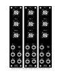
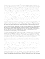
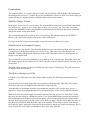
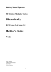
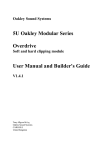
Oakley Sound Systems
The MultiMix
PCB issue 4
CV and Audio Mixer
User’s Guide
V4.5.0
Tony Allgood B.Eng
Oakley Sound Systems
CARLISLE
United Kingdom
The three variations of the Oakley Multimix. Each one is 1U wide by 5U high.
Introduction
The MultiMix is a highly useful utility module that can be obtained in three variations:
MultiMix Sum
The basic version of the MultiMix. This operates as a standard mixer. Up to three inputs, either CV
or audio, can be summed or mixed together. The levels for each input can be set by a pot. The gain
can be set from completely off to a little over one. Two mix outputs are available: One is +OUT and
this is simply the three inputs added together according to the levels set by the pots. The other is
-OUT and this is an inverted version of the signal at +OUT. This means if the output from +OUT is
+4V, then the output from -OUT is -4V.
A bicolour LED is also featured. This will glow when a signal is present at the outputs. The higher
the output the brighter the LED. The colour of the LED will be determined by the output polarity. It
will be red for mostly positive output voltages, and green for negative.
MultiMix Standard
This one is similar to the MultiMix Sum, but instead of ordinary pots to set the input levels, this one
features three reversible attenuators. Each control knob can be set so that the gain of the input is
anything from -1.1 to +1.1. This means that not only can inputs be added together, but can subtract
as well. With each input knob set to its middle position, then none or very little of the input signal
will reach the output.
Mixer's with reversible attenuators on their inputs are very useful for controlling audio and CVs.
One excellent application uses a MultiMix with a VCA to create a very flexible ring
modulator.
MultiMix Stooge
This one is similar to the MultiMix Standard and has the three reversible attenuators controlling the
input levels. However, this one features a clever combination of three output sockets to achieve a
variety of uses.
Inserting a jack into OUT1 and you will find a controlled version of the signal going into IN1. The
pot will control the level of the signal as well as its phase. You can thus use this to attenuate, or
invert, CV or audio signals around your modular. The other two input channels will work in a
similar way.
But if you don't utilise the OUT1 jack, then its output will automatically be summed with IN3 to
form a mixed output at OUT3. Likewise, not using OUT2 will make its output join with the IN3
signal too. So you can use this module as a standard MultiMix if you don't use the OUT1 and OUT2
sockets.
Although the three variants use different front panel designs, all are made from the same PCB. The
different versions are simply selected by using different components and inserting some wire links
into the board.
The PCB
The issue 4 MultiMix module features a two PCB set. Previously, many Oakley modules have had
the sockets, switches and extra pots wired to the board by individual wires. The MultiMix allows all
the socket wiring to be done via an extra PCB and two MTA or Molex KK solderless connections.
If you are building this module in the standard MOTM and Oakley format this new system will
reduce assembly time and possible wiring errors.
Some people will wish to use this Oakley design in a non standard format, such as fitting it to a
Analogue Solutions rack or one of their own invention. This is perfectly easy to do. Simply do not
use the socket board and wire the main board to the sockets as per usual.
I have provided space for the three control pots on the PCB. These can be mounted away from the
PCB, but they can form part of the mounting process. If you use the specified pots and brackets, the
PCB can be held very firmly to the front panel. Four M3 sized holes are provided on the PCB for
supporting the board if you choose to use other methods of mounting.
The pot spacing is 1.625” and is the same as MOTM modular synthesiser. The main board is fully
MOTM panel compatible if the board is fitted vertically, ie. in a 1U wide panel. Please note that the
sockets are mounted on a slightly different grid to the MOTM range.
There are detailed instructions later in this document about how to build the boards.
Circuit Description
The MultiMix circuit is quite simple, but let’s run through the design carefully.
Power is supply via the usual four way MTA or Molex connector. As is the custom for Oakley
modules, I have used ferrite beads to act as high frequency filters on the power lines. Decoupling at
the point of entry is provided by C15 for the positive rail, and C7 for the negative rail. Additional
decoupling is also provided elsewhere on the board by the other capacitors shown. These capacitors
keep the power supply clean of noise, and provide a reservoir for the little bursts of current that the
circuit takes in normal operation.
Two grounds are provided, one for the circuit itself, and one for the earthing of the jack sockets on
the front panel.
Note also the provision of six wire links on the board. These are to select which module variant is to
be built. A full description of which link to fit for each variant is given in the parts list.
There are six ICs, U1 to 6, on this PCB, and each requires power. The power supply to each IC is
shown separately at the bottom of the schematic to avoid cluttering the main circuit pathways. All
the ICs are simple dual op-amps and require both negative and positive supplies.
Three of the inputs have identical ‘reversible attenuator’ circuits. In issue one and two of the
Oakley MultiMix, I used a circuit that I found in the student engineers bible, The Art of Electronics
by Horowitz and Hill. Now this little circuit is great. Its simple, cheap and works very well, but it
does have one problem. That is, its input resistance changes as you turn the pot. In reality this has
very little effect on the way you use your modular. However, being the perfectionist that I am I
decided to do it differently in issue three. This has doubled the amount of op-amps in the circuit, but
now we have a constant input resistance whatever the pots’ position. Issue 4 boards share the same
improved input circuitry but there are some subtle changes to make the MultiMix more flexible.
Let us consider the first reversible attenuator. This is connected to IN1 and has its output at OUT1.
The circuit is made up from three op-amps. U1a (pins 1, 2, 3) acts simply as a voltage buffer. This
is a circuit that merely ‘sniffs’ the input voltage and creates a copy of that signal at its output on pin
1. We are free to take a bucket full of current from this output without affecting the input at all. A
bucket full of current must be defined here as anything less 15mA or so...
U1b (pins 5, 6, 7) is a different circuit to the one around U1a. This is an amplifier with a gain of
minus one. The negative bit means that its output is the opposite polarity to the input voltage. The
input voltage is sensed by R7, and the current flowing through R7, is matched by an equal current
flowing in R10. The op-amp does this because it adheres to the ‘golden rules’. Actually, it can only
try to adhere to these golden rules.
Now the golden rule in question is that an op-amp with negative feedback must move its output so
that its two input pins are both the same voltage. The negative feedback is provided by the resistor
R10. So as the input signal tries to inject current into the op-amps inverting (-) pin via R7, the
output will move against this by taking that current away through R10.
So a positive input voltage at R7 will lead to the output going negative. The ratio of the resistors
will determine the gain of the inverting circuit. Making both the resistors the same value will mean
that the gain of the op-amp is -1. That is 2V at the input gives us -2V at pin 7.
As far as the connected input goes, it does not see what then happens to these two copies of itself. It
only ‘sees’ the resistance of R7 and R1. Hang on, what's that R1 doing? Well R1 is only there to
make sure that the input is not just floating in thin air with nothing attached. This is useful for when
the circuit is not plugged in. Any stray static electricity cannot build up on this input and destroy the
op-amp. Actually this is very unlikely, but it is good practice. R1 is of a high enough value so as not
to affect the circuit sensitivity. R2 offers some sort of protection for U1a in any overvoltage
situation. A typical example of this is trying to use the inputs when the MultiMix module is not
powered up.
Lets go back to our two copies of the input signal. Remember that one is an exact copy, and one is
an inverted version. The exact copy firstly goes to a wire link switch, called LK1 and made from
three solder pads. You simply solder a wire link between the middle pad and either one of its outer
pads. It acts as a permanent switch built into the board when you populate the PCB. This ‘switch’
will connect the counter clockwise side of the LEVEL1 pot to either the output of U1a, the exact
copy of our input signal, or to ground. Let us first assume that LK1 is joined between 1 and 3 and
joins the pot with the op-amp output.
We now have the two versions of the input signal placed across the two ends of the control pot. As
the wiper moves from one side to the other, it will tap off a proportion of each signal. Consider
what will happen with a +10V input signal at IN1. This will give +10V at the output of U1a and
-10V at the output of U1b. The wiper of the pot can thus move from +10V to -10V. In the middle
position, both voltages take equal precedence and the voltage at the wiper is zero.
The voltage at the wiper is connected to another inverting amplifier based around U4a. The opamp’s gain is set to be -1.09. So a voltage of +10V at the wiper of the pot, will give +10.9V at the
op-amp’s output. It is this output that drives the next section of the MultiMix circuit in the standard
layout. In the ‘Stooge’ layout we use this output directly, and because of this the op-amp is
configured for maximum stability
Note that the gain is not set to be exactly -1. This is because many users desire the Multimix to be
able to have a gain of exactly one, or unity, overall. This would be very difficult to achieve without
trimmers because of the tolerances of the gain setting resistors. You would also have to allow for
the possible loss of signal within the pots and that due to any output resistance of the connected
source modules. The output resistance is an unknown quantity thus the overall gain would vary
slightly depending on which module you connected up to the Multimix. However, by providing
each stage with slightly more than unity gain it is still possible to dial up a gain of one with the front
panel pots by backing them off slightly from their maximum position.
C8 and R13 form part of the stabilising network designed to keep the op-amp from oscillating under
capacitive loads. Capacitive loads are easily created in a patch cord synthesiser. Each patch cord
acts as a low value capacitor to ground. This can make an op-amp very unhappy and its output will
oscillate, often at very high frequencies. In issue 1 of the MultiMix, and many other modules, this
stabilisation was simply achieved by a 1K resistor in series with the output load. However, this
causes the output voltage to fall with increasing load. In the Stooge layout this would create
increasing DC errors as more modules are connected the output.
Issue 3, and now 4, resolved this matter, by using a more active approach using C8 and R13. A full
explanation of their action is beyond the scope of this User guide, but more information can be
found on the Analog Devices website in their Applications Note AN-257. I was first introduced to
this method when I worked at Soundcraft, and have since used it on other many Oakley projects.
Let us go back to LK1 again. Imagine now if the link was connected pads 2 and 3. This means that
the output of U1a will be unused, and the pot’s counter clockwise pin will connected to ground.
This is means that the pot’s wiper will now start from zero volts instead of the inverted version of
the input. This is the mode used in the MultiMix Sum module. It allows each pot to act as a
conventional level control and not as a reversible attenuator.
U6b forms a summing amplifier. Currents flowing through all the input resistors, R29 and 30, come
together at the inverting input. The op-amp’s output will alter to create the same current through
R28. Since the value of all three resistors are the same the op-amp must produce the same voltage
as presented at a single input. In other words, the gain of the summing stage is just over one. In fact,
its actually minus one, since the output voltage is always an inverted sum of all the inputs.
In the Standard and Sum modules this summing amplifier takes the outputs of the first two input
channels directly and sums them together. It does this by the fitting of two further links, LK4 and
LK5.
In the Stooge module, things are a little more complex. U6b will sum the two outputs together but
only if there are no jacks inserted into OUT1 and OUT2 on the front panel. This clever automatic
switching is achieved by using the ‘normally closed’ (NC) contacts on the jack sockets. The links
LK4 and LK5 are not fitted in this case, and a five way socket called OUT carries the outputs and
the returning signals between the MultiMix circuitry and output boards.
The output of U6b is fed directly into the output stage of the third input channel. Thus all three
signals will be summed into this output, OUT3. Note that the inversion caused by U6b is nor
corrected by the inverting nature of U6a.
In the Standard and Sum versions of the MultiMix, the output of U6a will be the main +OUT. But
these modules also feature an inverted output too. This is created by another inverting circuit
complete with stabilising components. U5a and associating circuitry does the job. This circuit turns
the summed voltage from U6a upside down.
From the output of U5a we now have the main ‘-OUT’ signal and this needs to be passed to the
appropriate socket on the front panel. This is done via a two way connection fitted into the bottom
two pins of OUT, and by fitting a wire link into LK6 between pads 1 and 3.
The Bicolour LED is a wonderful little thing. Its a simple design really, its just two LED chips of a
different colour placed in the same clear package. Both LEDs are fitted in parallel, but the opposite
way round. So the direction of current determines the colour seen.
Because the LED is really a diode, it doesn’t switch on at any voltage. Each LED requires a certain
voltage across the device for it to even glow dimly. In fact, different colours require different
voltages. And too much voltage will kill them, permanently. If you connected the LED directly to a
voltage source which was ramped up from 0 to +10V, the LED would at first be off, start to glow at
about 2V and then probably get very bright very quickly. And then burn out with a final burst of
brilliant light. (Ah! A short life, but a good one... and you’ve just seen 15 pence worth of semiconductor destroyed)
The MultiMix connects the LED in the feedback path of an inverting op-amp amplifier, U5b. So
any current going through the input resistor, R27, will be the same as the current in the LED and
R26. Thus, the LED is controlled by current not voltage. The op-amp’s output will adjust
automatically to create the correct voltage for a desired current. The LED can’t blow out as the opamp won’t supply that amount of current. The LED won’t be off at low levels of input voltage,
because the op-amp always makes sure that even a little input voltage will create a little current.
R27 controls the sensitivity of the circuit. 1K5 produces about 7 mA through the LED for a 10V
output of the MultiMix. You may want to reduce this to 1K, to give a brighter reading. Personally, I
think 7 mA is fine for most applications indoors. Another thing to bear in mind when you want a
brighter LED, is that the current must come from somewhere. Both U5a’s output and U5b itself will
have to provide this current, and both devices will protest if you try to take too much current out of
them. Plus, you have to think about the power consumption of your modular itself. Too many pretty
lights will start to demand too much of your power supply.
In the Stooge version we have no inverted output or LED. So the whole of the circuitry
surrounding, and including U5, can be omitted.
Parts List
For general information regarding where to get parts and suggested part numbers please see our
useful Parts Guide at the project webpage or http://www.oakleysound.com/parts.pdf.
The components are grouped into values, the order of the component names is of no particular
consequence.
A quick note on European part descriptions. R is shorthand for ohm. K is shorthand for kilo-ohm. R
is shorthand for ohm. So 22R is 22 ohm, 1K5 is 1,500 ohms or 1.5 kilohms. For capacitors: 1uF =
one microfarad = 1000nF = one thousand nanofarad.
To prevent loss of the small ‘.’ as the decimal point, a convention of inserting the unit in its place is
used. eg. 4R7 is a 4.7 ohm, 4K7 is a 4700 ohm resistor, 6n8 is a 6.8 nF capacitor.
IMPORTANT NOTE: There are three different variations for this module. Make sure you get the
right parts list. The Standard and Sum versions share the same parts list and differ only in the
position of three links. The Stooge version requires a rather different parts list.
MultiMix Standard and MultiMix Sum Variants
Links
These links can be made from component leg clippings or uninsulated tinned copper wire. Simply
solder a small hoop of wire joining the relevant pads of each link. Note: for the ‘three pad links’ pad
1 is the square pad at one end, pad 3 is middle pad, and pad 2 is the round pad on the end.
MultiMix Standard
LK1, LK2, LK3
LK6
Link pads 1 and 3
Link pads 1 and 3
Link out LK4 and LK5.
MultiMix Sum
LK1, LK2, LK3
LK6
Link pads 2 and 3
Link pads 1 and 3
Link out LK4 and LK5.
Resistors
5% 1/4W carbon or better.
75R
1K5
10K
15K
22K
24K
R13, R23, R19, R16
R27
R2, R3, R6
R26
R15, R25, R22, R28, R30, R29
R14, R24, R20, R21, R18, R17
100K
470K
R7, R10, R11, R8, R9, R12
R1, R4, R5
Capacitors
33pF low-K ceramic plate
100pF low-K ceramic plate
2u2, 63V electrolytic
100nF, 63V axial ceramic
C8, C16, C10, C9
C17
C15, C7
C1, C2, C3, C4, C5, C6, C11, C12, C13, C14
Discrete Semiconductors
5mm Bicolour LED
1 off, fitted externally
Integrated Circuits
TL072 dual Bi-FET op-amp
U1, U2, U3, U4, U5, U6
Miscellaneous
4-way 0.156” MTA header
5-way 0.1” MTA header
5-way 0.1” MTA housing
2-way 0.1” MTA header
2-way 0.1” MTA housing
Leaded Ferrite beads
LED clip/lens
Sockets
50K lin Spectrol 248
Oakley-Spectrol Solder brackets
PWR
IN (Main PCB and I/O PCB)
IN cable
OUT (Main PCB and I/O PCB)**, LED
OUT cable, LED cable
L1, 2
LED
Switchcraft APC112
LEVEL1, LEVEL2, LEVEL3
LEVEL1, LEVEL2, LEVEL3
1 off
2 off
2 off
3 off
4 off
2 off
1 off
5 off
3 off
3 off
Around 2 m of insulated multistrand wire (26awg)
** The 2-way 0.1” header is fitted into pins 4 and 5 of the OUT location.
You may well want to use 8-pin DIL sockets for the ICs. I would recommend low profile turned pin
types as these are the most reliable. You need six of them.
MultiMix ‘Stooge’ Variant
Links
These links can be made from component leg clippings or uninsulated tinned copper wire. Simply
solder a small hoop of wire joining the relevant pads of each link. Note: for the ‘three pad links’ pad
1 is the square pad at one end, pad 3 is middle pad, and pad 2 is the round pad on the end.
LK1, LK2, LK3
LK6
Do not fit LK4 and LK5.
Link pads 1 and 3
Link pads 2 and 3
Resistors
5% 1/4W carbon or better.
75R
10K
22K
24K
100K
470K
R13, R23, R19
R2, R3, R6
R15, R25, R22, R28, R30, R29
R14, R24, R20, R21
R7, R10, R11, R8, R9, R12
R1, R4, R5
The following parts are not fitted:
R16, R17, R18, R26, R27
Capacitors
33pF low-K ceramic plate
2u2, 63V electrolytic
100nF, 63V axial ceramic
C8, C16, C10
C15, C7
C1, C2, C3, C4, C5, C6, C11, C12, C13, C14
The following parts are not fitted:
C9, C17
Integrated Circuits
TL072 dual Bi-FET op-amp
U1, U2, U3, U4, U6
U5 is not fitted.
Miscellaneous
4-way 0.156” MTA header
5-way 0.1” MTA header
5-way 0.1” MTA housing
Leaded Ferrite beads
Sockets
50K lin Spectrol 248
Oakley-Spectrol Solder brackets
PWR
IN, OUT (Main PCB and I/O PCB)
IN, OUT cables
L1, 2
Switchcraft APC112
LEVEL1, LEVEL2, LEVEL3
LEVEL1, LEVEL2, LEVEL3
1 off
4 off
4 off
2 off
6 off
3 off
3 off
Around 2 m of insulated multistrand wire (26awg)
You may well want to use 8-pin DIL sockets for the ICs. I would recommend low profile turned pin
types as these are the most reliable. You need five of them.
Populating the Main MultiMix Circuit Board
Occasionally people have not been able to get their Oakley projects to work first time. Some times
the boards will end up back with me so that I can get them to work. The most common error with
most of these was parts inserted into the wrong holes. Please double check every part before you
solder any part into place. Desoldering and removing parts on a double sided board is a skill that
takes a while to master properly.
If you have put a component in the wrong place, then the best thing to do is to snip the component’s
lead off at the board surface. Then using the soldering iron and a small screwdriver prize the
remaining bit of the leg out of the hole. Then use wick or a good solder pump to remove the solder
from the hole. Filling the hole with fresh solder will actually make the hole easier to suck clean!
Sometimes people like to substitute parts in place of my own recommendations. Feel free to do this,
but remember that there is normally a good reason why I have selected that particular part. If you do
find that, say changing an op-amp with another one, makes an improvement, please do let me know
either via the Oakley-Synths list or directly to me.
All resistors should be flat against the board surface before soldering. It is a good idea to use a ‘lead
bender’ to preform the leads before putting them into their places. I use my fingers to do this job,
but there are special tools available too. Once the part is in its holes, bend the leads that stick out the
bottom outwards to hold the part in place. This is called ‘cinching’. Solder from the bottom of the
board, applying the solder so that the hole is filled with enough to spare to make a small cone
around the wire lead. Don’t put too much solder on, and don’t put too little on either. Clip the leads
off with a pair of side cutters, trim level with the top of the little cone of solder.
Once all the resistors have been soldered, check them ALL again. Make sure they are all soldered
and make sure the right values are in the right place.
The axial multilayer ceramics can be treated like resistors. Simply bend their legs to fit the 7.5mm
(0.3”) spacing holes.
IC sockets are to be recommended, especially if this is your first electronics project. Make sure, if
you need to wash your board, that you get water in and around these sockets. Also, make sure that
any water drops left between the pins of the sockets are fully dried up before switching the board
on.
The smaller electrolytic capacitors are very often supplied with 0.1” lead spacing. My hole spacing
is 0.2”. This means that the underside of these radial capacitors will not go flat onto the board. This
is deliberate, so don’t force the part in too hard. The capacitors will be happy at around 0.2” above
the board, with the legs slightly splayed. Sometimes you will get electrolytic capacitors supplied
with their legs preformed for 0.2” (5mm) insertion. This is fine, just push them in until they stop.
Cinch and solder as before. Make sure you get them in the right way. Electrolytic capacitors are
polarised, and may explode if put in the wrong way. No joke. Oddly, the PCB legend marks the
positive side with a ‘+’, although most capacitors have the ‘-’ marked with a stripe. Obviously, the
side marked with a ‘-’ must go in the opposite hole to the one marked with the ‘+’ sign. Most
capacitors usually have a long lead to depict the positive end as well.
The 0.1” and 0.156” headers are fitted on the main board so that pin 1 is towards the top of the
board. The clip on the side of the header will match with the picture on the PCB legend, ie. towards
the location of the pots.
For the Standard and Sum variations you need to use a 2-way header for the OUT
interconnection. The header should be fitted so that it takes the bottom two places of the five
holes on the main board. That is, you should make sure the top three holes that lie above the
header are still visible. The Standard and Sum variants use pin 4 and 5 only. The Stooge
version uses all five pins.
I would make the main circuit board in the following order: resistors, IC sockets, small non-polar
capacitors, electrolytic capacitors, and connectors. Then the final water wash if you have used
solder with water based flux.
Do not fit the pots at this stage. The mounting of the pots requires special attention. This will be
covered later in this User Guide.
Populating the Socket Boards
You have one socket board to populate and the method is a little unusual.
On the board the first things to solder are the headers. These are fitted to the BOTTOM of the
board and are soldered from the top side. This is obviously opposite to what you are normally used
to. The legending is on the top of the board, and the bottom of the board is marked as such in
copper on the underside.
Fit the INPUT header so that pin 1 is the square pin. The friction lock on the header should
correspond to the legend on the top, ie. the opposite side, of the board. In other words the friction
lock is facing the bottom of the module.
The actual type of header used for the OUTPUTS interconnect will depend on the variation of the
MultiMix you are building. If you are building the Stooge version, you will need to fit a five way
header to OUTPUTS. This again is fitted on the bottom of the board like you have just done for the
IN header.
If you are building the Standard or Sum variant, then you need to take a little extra care
when soldering the OUTPUTS header.
You are using a two way header and it will be fitting into a location that seemingly has five
pads. Three of these pads will not be used. This needs to be fitted so that you will utilise pins 4
and 5 of the header only.
This means that pin 1 of the header itself should correspond to pin 4 on the board. In other
words, you should fit the header so that the three pads, pins 1, 2 and 3, are still visible to the
left of the fitted header. Remember that pin 1 on the board is designated with a square pad.
The sockets will be fitted on the top of the board, and therefore be soldered on the bottom of the
board. You may well find your own way of soldering the sockets, but the way I do it is as follows:
Fit all your sockets into the board. The bevel edge should align with the picture on the board
legending. Do not solder them at this stage. Take your front panel and align this over the sockets.
Those of you building the Standard or Sum variant will not need to fit the socket labelled
OUT1.
Now carefully place your front panel with PCB and sockets upside down onto your bench [or
kitchen table!]. The holes where the sockets will be should hang over the edge of the bench so that
the sockets aren’t forced back up through the holes. You’ll also probably need a small counter
weight to stop the panel from falling over the edge. Now allowing the PCB to rest flat on top of the
sockets, you can begin to solder all the pins to the board.
Those of you who have built older Oakley modules will be stunned how easy this was compared
with the making of wire frames done previously.
Mounting the Pots
The first thing to do is to check your pot values. Spectrol/Vishay do not make it that easy to spot pot
values. Your pot kit should contain:
Value
Marked as
Quantity
Location
50K linear
M248 50K M
3 off
Main PCB
Fit the pot brackets to the pots by the nuts supplied with the pots. You should have two nuts and one
washer per pot. Fit only one nut at this stage to hold the pot to the pot bracket. Make sure the pot
sits more or less centrally in the pot bracket with legs pointing downwards. Tighten the nut up
carefully being careful not to dislodge the pot position. I use a small pair of pliers to tighten the nut.
Do not over tighten.
Now, doing one pot at a time, fit each pot and bracket into the appropriate holes in the PCBs. Solder
two of the pins attached to the pot bracket. Leave the other two pins and the three pins of the pot
itself. Now check if the pot and bracket is lying true. That is, all four pins are through the board,
and the bracket should be flat against the board’s surface. If it is not, simply reheat one of the
bracket’s soldered pads to allow you to move the pot into the correct position. Don’t leave your iron
in contact with the pad for too long, this will lift the pad and the bracket will get hot. When you are
happy with the location, you can solder the other two pins of the bracket and then the pot's pins. Do
this for both pots and snip off any excess wire from the pot's pins at this point.
You can now present the front panel up to the completed board to check that it fits. If it does, then I
mount the board up proper. You need to add the washer between the panel and the final nut. Again,
do not over tighten and be careful not to scratch your panel.
The pots shafts of the three pots will not need cutting to size. They are already at the correct length.
The Spectrol pots are lubricated with a light clear grease. This sometimes is visible along the top of
the mounting bush of the pot body. Try not to touch the grease as it consequently gets onto your
panel and PCB. It can be difficult to get off, although it can be removed with a little isopropyl
alcohol on cotton wool bud.
Connections
This is the bit where you connect the two boards, and possibly the LED, together. The boards have
been designed to accept 0.1” headers for quicker manufacture. However, there is no reason why you
cannot join the two boards together with hand soldered wire interconnects.
MultiMix Stooge Variant
Make up the first of two five way headers. The first should be made from wires 80 mm long. Make
sure you get pin 1 going to pin 1 on the other housing, pin 2 to pin 2, etc. This cable carries the
inputs to the MultiMix circuitry and should be connected to the INPUTS header on the I/O board
and the IN header on the main board.
The second and final lead is made up to be 130 mm long. This should connect the OUTPUTS
header on the I/O board with the OUT header on the main board.
If you get them the wrong way around the circuit won’t blow up, but it won’t work.
MultiMix Sum and Standard Variants
Make up one five way header. This should be made from wires 80 mm long. Make sure you get pin
1 going to pin 1 on the other housing, pin 2 to pin 2, etc. This cable carries the inputs to the
MultiMix circuitry and should be connected to the INPUTS header on the I/O board and the IN
header on the main board.
The second lead is a two way interconnect. It is made up to be 130 mm long. This cable carries the
two output signals. It will connect the OUTPUTS header on the I/O board to the OUT header on the
main board.
The third lead is another two way lead. Make this interconnect 130mm long. This will connect the
LED to the main circuit board.
The Molex Alternative to MTA
For those of you who want to use the cheaper Molex system, the following information may be
useful:
A quick note on the female plugs; these are sometimes called housings, since they aren’t plugs
themselves but merely housings for the individual crimp terminals.
Terminals have to be bought in packs of one hundreds, but this is OK, because they are not
expensive. These are normally designed to be crimped but they can be easily soldered with care.
Make each wire the correct length. I normally strip back the wire by just 2 to 3mm. Place all the
bare wire into the crimp on a heatproof surface. I use 12mm MDF board to protect my bench top,
which although not at all burn proof will take plenty of heat from a soldering iron without major
damage. Rest a pair of pliers on top of the wire to hold it in place. Slip the crimp under the wire, so
that the wire’s insulation butts up to the edge of the terminal. Then solder in place. Sometimes I
find I need to gently squash the crimp part of the terminal so that it will fit into the housing. This is
easier to do before you solder it, although it can be done after with care.
Do not use the water washable flux solder in this application. You must use either good old
fashioned ersin or rosin flux based solders or the newer so called ‘no-clean’ types. I actually prefer
the rosin based ones for this because I find they flow better. Once you have soldered it, wait a bit
for it to cool, and then push it into the housing until it clicks. If it doesn’t go in, then take it out and
bend the crimp slightly backwards. Now try again.
I like to use as many different colour wires as possible. It makes wiring easier and looks great. And
it also helps to make sure that pin 1 on one header is connected to pin 1 on the other.
Power Connections
The power socket is 0.156” Molex/MTA 4-way header. Friction lock types are recommended. This
system is compatible with MOTM systems.
Power
+15V
Module GND
Earth/PAN
-15V
Pin number
1
2
3
4
As stated before the PAN pad on the PCB has been provided to allow the ground tags of the jack
sockets to be connected to the powers supply ground without using the modules 0V supply. Earth
loops cannot occur through patch leads this way, although screening is maintained. Of course, this
can only work if all your modules follow this principle.
Testing, testing, 1, 2, 3...
Apply power to the unit making sure you are applying the power correctly. Check that no device is
running hot. Any sign of smoke or strange smells turn off the power immediately and recheck the
polarity of the power supply, and the direction of the ICs in their sockets.
Assuming everything is OK so far, it is time to apply an audio input. Use a bright signal like a
sawtooth output from a VCO. Middle A, 440Hz is a good note to use.
Connect up an amplifier or mixing desk input to the OUT3 or OUT+ socket. Now connect your
signal to the first input. You should be control the level with the top pot. If you have built the
Standard or Stooge version, you should be able to silence the input by moving the pot to its middle
position. If you have built the Sum version, the pot should act as an ordinary volume control.
Input channels two and three should perform identically. If you have an LED, then this should glow
when there is a signal present at the output. The larger the signal the brighter the LED.
If you have built the Sum or Standard versions, check the OUT- socket. This should behave in the
same way as the OUT+ socket. The output will be inverted but it should still sound the same.
Stooge builders should now check the output from OUT1 and OUT2. OUT1 should be a controlled
version of IN1, and OUT2 should be a controlled version of IN2. Inserting a jack plug into either
OUT1 or OUT2 will cut the respective input from the OUT3 socket.
Final Comments
If you have any problems, an excellent source of support is the Oakley Sound Forum at
Muffwiggler.com. Paul Darlow and I are on this group, as well as many other users and builders of
Oakley modules.
If you can't get your project to work, then Oakley Sound Systems are able to offer a 'get you
working' service. If you wish to take up this service please e-mail me, Tony Allgood, at my contact
e-mail address found on the website. I can service either fully populated PCBs or whole modules.
You will be charged for all postage costs, any parts used and my time at 25GBP per hour. Most
faults can be found and fixed within one hour, and I normally return modules within a week. The
minimum charge is 25GBP plus return postage costs.
If you have a comment about this builder's guide, or have a found a mistake in it, then please do let
me know. But please do not contact me or Paul Darlow directly with questions about sourcing
components or general fault finding. Honestly, we would love to help but we do not have the time
to help everyone individually by e-mail.
Last but not least, can I say a big thank you to all of you who helped and inspired me. Thanks
especially to all those nice people on the Synth-diy, Oakley-Synths and Analogue Heaven mailing
lists and those at Muffwiggler.com.
Tony Allgood at Oakley Sound
This User Guide was originally prepared in September 2005
Last Updated: October 2010
No part of this document may be copied by whatever means without my permission.