1
MICROS e7
Version 2.8
ReadMe First
General Information
About This
Document
ReadMe First is an introduction to the new features, enhancements and
revisions added in the Version 2.8 release of the MICROS e7 product.
Product information is divided into the following sections:
MICROS e7 Installation
What’s New
What’s Enhanced
What’s Revised
Version 2.8
MD0007-039
August 11, 2009
Page 1 of 62
General Information
Declarations
Declarations
Warranties
Although the best efforts are made to ensure that the information in this
manual is complete and correct, MICROS Systems, Inc. makes no
warranty of any kind with regard to this material, including but not
limited to the implied warranties of marketability and fitness for a
particular purpose. Information in this manual is subject to change
without notice. No part of this manual may be reproduced or transmitted
in any form or by any means, electronic or mechanical, including
photocopying, recording, or information recording and retrieval systems,
for any purpose other than for personal use, without the express written
permission of MICROS Systems, Inc.
MICROS Systems, Inc. shall not be liable for errors contained herein or
for incidental or consequential damages in connection with the
furnishing, performance, or use of this manual.
Trademarks
Framemaker is a registered trademark of Adobe Corporation.
Microsoft and Windows are registered trademarks of Microsoft
Corporation in the United States and/or other countries.
All other trademarks are the property of their respective owners.
MD0007-039
August 11, 2009
Page 2 of 62
Version 2.8
General Information
Introduction
Introduction
MICROS e7 is a robust point-of-sale solution, with the high quality,
reliable and extensive features that the marketplace has grown to expect
from MICROS. All of this has been packaged specifically for the
independent restaurateur.
MICROS e7 is a complete solution that utilizes the revolutionary
MICROS Workstation POS terminal platform and MICROS' 30 plus
years of industry leading software solutions.
The MICROS e7 user interface offers an intuitive, user-friendly
touchscreen design that takes advantage of color, font, and an efficient
screen layout to guide servers through the order entry process. The
simplicity of the design reduces training time, improves speed of service
to the customer, and lowers error rates for daily operations.
For more information about the MICROS e7 product, refer to the
following resources:
Marketing Overview - This manual provides information regarding
MICROS, the hospitality industry, features and benefits, sample
reports, and a proposed return on investment for MICROS e7. This
document is available for download from the MICROS website e7 |
Marketing | e7 Marketing Overview.
User’s Manual - This manual provides information on how to use
the MICROS e7 System, including POS Operations, Manager
Procedures, Credit Card Batch, and Reporting. This document is
available for download on the MICROS website e7 | e7 [Release
Version] | Documentation | e7 User’s Manual.
Version 2.8
MD0007-039
August 11, 2009
Page 3 of 62
MICROS e7 Installation
Introduction
MICROS e7 Installation
In order to successfully install and use the MICROS e7 product, the user
must upgrade both the PC and workstations to the 2.0 Version of the
Microsoft .NET Framework or the .NET Compact Framework
respectively.
Attempting to upgrade MICROS e7 to Version 2.8 without performing a
framework upgrade, will cause the installation to fail and an error
message to appear.
The following error message will appear on a PC:
If this occurs select [Ok] to clear the error message and follow the
instructions outlined in the MICROS e7 PC Installation section.
The following error message will appear when attempting a stand-alone
workstation installation:
If this occurs select [Ok] to clear the error message and follow the
instructions outlined in the Workstation Platform Image section.
MD0007-039
August 11, 2009
Page 4 of 62
Version 2.8
MICROS e7 Installation
Upgrading From a Non-PCI Compliant Version of Software
Upgrading From a
Non-PCI Compliant
Version of
Software
Visa established the Payment Card Industry (PCI) Data Security Standard to
protect Visa cardholder data—wherever it resides—ensuring that members,
merchants, and service providers maintain the highest information security
standard. Please see the MICROS e7 PABP Compliance document for the
appropriate software version for additional information.
Non-PCI compliant versions of MICROS e7 may allow sensitive information,
such as credit card numbers, to exist in a non-encrypted format. Such historical
data (magnetic stripe data, card validation codes, PINs, or PIN blocks) must be
removed. Removal of such data is necessary to ensure the MICROS software
upgrade is conducted in a manner that is PCI compliant.
The table below lists all of the PCI compliant and non-PCI compliant versions
of MICROS e7.
Non-PCI Compliant
Version
1.0
1.5
1.5 Patch 1
2.0
2.0 Patches 1 & 2
Compliant PCI Versions
2.1
2.1 Patches 1, 2, 3 & 4
2.5
2.6 Patches 1, 2 & 3
2.7 Patches 1 & 2
2.8
For information on upgrading a MICROS e7 system from a non-PCI compliant
version to a PCI compliant version see the MICROS e7 Version 2.7 Payment
Application Best Practices Implementation Guide, MD0007-032
documentation.
Version 2.8
MD0007-039
August 11, 2009
Page 5 of 62
MICROS e7 Installation
Before You Begin
Before You Begin
MICROS recommends backing up the MICROS e7 database before
performing an update to the system. Follow these steps to backup the
database:
1. Go to the MICROS e7 Configurator.
2. Select the down arrow on the right-hand side of the screen.
3. A list of available operations will appear. Select Backup the
Database.
4. A backup of the database will be written to the
\MICROS\e7\DbBackups folder.
MD0007-039
August 11, 2009
Page 6 of 62
Version 2.8
MICROS e7 Installation
Before You Begin
Restore
Database
Restoring a database is NOT part of the standard MICROS e7 installation
process. If for any reason the user needs to restore a database, follow
these steps:
1. Go to the MICROS e7 Configurator.
2. Select the down arrow on the right-hand side of the screen.
3. A list of available operations will appear. Select Restore the
Database.
4. The database will be restored from the \MICROS\e7\DbBackups
folder.
Version 2.8
MD0007-039
August 11, 2009
Page 7 of 62
MICROS e7 Installation
Downloading the MICROS e7 Product
Downloading the
MICROS e7
Product
The MICROS e7 product is available for download from the MICROS
Web Site. There are several download choices available from the
Member Services | Product Support | MICROS Products page:
Workstation Platform Image - The platform image will depend on
the type(s) of workstation(s) in use at the site. The following images
are available:
Workstation 4. Download this file to extract the platform image
for a Workstation 4. Use the e7 | e7 [Release Version] |
Workstation 4 Platform Software link to download the
e7_ws4_platform_15_2.exe file.
Workstation 4 LX. Download this file to extract the platform
image for a Workstation 4 LX. Use the e7 | e7 [Release Version] |
Workstation 4 LX Platform Software link to download the
appropriate e7_ws4lx_platform_RC_2.9_and_BIOS.exe file.
Workstation 5. Download this file to extract the platform image
for a Workstation 5. Use the e7 | e7 [Release Version] |
Workstation 5 Platform Software link to download the appropriate
e7_ws5_platform_RC_1.3_and_BIOS.exe file.
MICROS e7 Workstation Installation - Download this file if you
are installing only to a workstation.
Use the e7 | e7 [Release Version] | e7 Workstation 4 Software link to
download the e7_ws4_build_2.8A.exe file.
Use the e7 | e7 [Release Version] | e7 Workstation 4 LX Software link
to download the e7_ws4lx_build_2.8A.exe file.
Use the e7 | e7 [Release Version] | e7 Workstation 5 Software link to
download the e7_ws5_build_2.8A.exe file.
MICROS e7 PC Installation - Download this file if you are
installing to a PC. The extracted files can be used to burn a CD or to
run the MICROS e7 PC Setup program.
Use the e7 | e7 [Release Version] | e7 PC Software link to download
the e7_pc_build_2.8A.exe file.
MD0007-039
August 11, 2009
Page 8 of 62
Version 2.8
MICROS e7 Installation
Downloading the MICROS e7 Product
Workstation
Platform
Image
The platform image and the installation instructions will vary based on
the workstation(s) being used at the site. This section is divided as
follows, refer to the appropriate instructions for your workstation
version.
Workstation 4
Workstation 4 LX
Workstation 5
Workstation 4
Use these instructions to install the Platform Image on a Workstation 4.
These steps may also be used to install another CE language platform,
such as Chinese, Japanese, or Korean.
The MICROS e7 software will not be installed as part of these
instructions. A PC or laptop is required to extract the zip (.exe) file and
copy the extracted files to the appropriate transfer media, such as a USB
thumb drive.
1. Copy the ws4_platform_15_2.exe file from the MICROS Web Site
to a temporary directory on the PC.
2. Double-click on ws4_platform_15_2.exe to extract the MICROS e7
files.
3. Enter a directory location where the MICROS e7 files will be
extracted (i.e., C:\wsImage).
4. Click on Unzip.
5. Click on Close.
6. Copy the directory from Step 3 (i.e., C:\wsImage) to a USB thumb
drive.
7. Attach the USB thumb drive to the USB slot on the back of the
Workstation 4.
Version 2.8
MD0007-039
August 11, 2009
Page 9 of 62
MICROS e7 Installation
Downloading the MICROS e7 Product
8. Open Windows Explorer on the Workstation.
9. Locate the MICROS e7 software directory (i.e., C:\wsImage) on the
USB thumb drive. The USB thumb drive should appear in Explorer
as \Hard Disk. The following two sub-directories should be available:
..\Standalone CAL Upgrade to 1.1.3.55.
..\Standalone Platform Update 15.2
10. From the ..\Standalone CAL Upgrade to 1.1.3.55 directory, run
StandAloneInstall.exe to upgrade the CAL client software on the
workstation.
Note
Make sure that each workstation has at least 25 MB of free
compact flash space before installing the software on the
workstation.
11. From the ..\Standalone Platform 15.2 directory, run
StandAloneInstall.exe to install the 15.2 platform. CAL installs the
Windows CE image and reboots the workstation.
Workstation 4 LX
Use these instructions to install the Platform Image on a Workstation 4
LX. These steps may also be used to install another CE language
platform, such as Chinese, Japanese, or Korean.
The MICROS e7 software will not be installed as part of these
instructions. A PC or laptop is required to extract the zip (.exe) file and
copy the extracted files to the appropriate transfer media, such as a USB
thumb drive.
1. Copy the ws4lx_platform_RC_2.9_and_BIOS.exe file from the
MICROS Web Site to a temporary directory on the PC.
2. Double-click on ws4lx_platform_RC_2.9_and_BIOS.exe to extract
the MICROS e7 files.
MD0007-039
August 11, 2009
Page 10 of 62
Version 2.8
MICROS e7 Installation
Downloading the MICROS e7 Product
3. Enter a directory location where the MICROS e7 files will be
extracted (i.e., C:\wsImage).
4. Click on Unzip.
5. Click on Close.
6. Copy the directory from Step 3 (i.e., C:\wsImage) to a USB thumb
drive.
7. Attach the USB thumb drive to the USB slot on the back of the
Workstation 4 LX. The user must insert the USB thumb drive into the
first USB port on the back of the workstation. Insert the thumb drive
to the USB port indicated below:
8. Open Windows Explorer on the Workstation.
9. Locate the MICROS e7 software directory (i.e., C:\wsImage) on the
USB thumb drive. The USB thumb drive should appear in Explorer
as \Hard Disk. The following three sub-directories should be
available:
Version 2.8
..\Standalone BIOS Update
..\Standalone CAL Upgrade to 6.1.3.68
..\Standalone Platform Update GR 1.1
MD0007-039
August 11, 2009
Page 11 of 62
MICROS e7 Installation
Downloading the MICROS e7 Product
10.From the ..\Standalone BIOS Update directory, run
StandAloneInstall.exe to upgrade BIOS on the workstation.
Note
Make sure that each workstation has at least 25 MB of free
compact flash space before installing the software on the
workstation.
11. From the ..\Standalone CAL Upgrade to 6.1.3.68 directory, run
StandAloneInstall.exe to upgrade the CAL client software on the
workstation.
12. From the ..\Standalone Platform 2.9 directory, run
StandAloneInstall.exe to install the 2.9 platform. CAL installs the
Windows CE image and reboots the workstation.
Workstation 5
Use these instructions to install the Platform Image on a Workstation 5.
These steps may also be used to install another CE language platform,
such as Chinese, Japanese, or Korean.
The MICROS e7 software will not be installed as part of these
instructions. A PC or laptop is required to extract the zip (.exe) file and
copy the extracted files to the appropriate transfer media, such as a USB
thumb drive.
1. Copy the ws5_platform_RC_1.3_and_BIOS.exe file from the
MICROS Web Site to a temporary directory on the PC.
2. Double-click on ws5_platform_RC_1.3_and_BIOS.exe to extract
the MICROS e7 files.
3. Enter a directory location where the MICROS e7 files will be
extracted (i.e., C:\wsImage).
4. Click on Unzip.
5. Click on Close.
MD0007-039
August 11, 2009
Page 12 of 62
Version 2.8
MICROS e7 Installation
Downloading the MICROS e7 Product
6. Copy the directory from Step 3 (i.e., C:\wsImage) to a USB thumb
drive.
7. Attach the USB thumb drive to the USB slot on the back of the
Workstation 5. The user must insert the USB thumb drive into the
first USB port on the back of the workstation. Insert the thumb drive
into the USB port indicated below:
8. Open Windows Explorer on the Workstation.
9. Locate the MICROS e7 software directory (i.e., C:\wsImage) on the
USB thumb drive. The USB thumb drive should appear in Explorer
as \Hard Disk. The following three sub-directories should be
available:
..\Standalone BIOS Update
..\Standalone CAL Upgrade to 6.1.3.68
..\Standalone Platform Update RC 1.3
10. From the ..\Standalone BIOS Update directory, run
StandAloneInstall.exe to upgrade BIOS on the workstation.
Note
Version 2.8
Make sure that each workstation has at least 25 MB of free
compact flash space before installing the software on the
workstation.
MD0007-039
August 11, 2009
Page 13 of 62
MICROS e7 Installation
Downloading the MICROS e7 Product
11. From the ..\Standalone CAL Upgrade to 6.1.3.68 directory, run
StandAloneInstall.exe to upgrade the CAL client software on the
workstation.
12. From the ..\Standalone Platform RC 1.3 directory, run
StandAloneInstall.exe to install the RC 1.3 platform. CAL installs
the Windows CE image and reboots the workstation.
MICROS e7
Workstation
Installation
Use these instructions to install the MICROS e7 software on a
Workstation that has the appropriate Windows CE operating system
image already installed. A PC or laptop is required to extract the zip file
and copy the extracted files to the appropriate transfer media, such as a
USB thumb drive.
The zip file will vary depending on workstation version being used at the
site. This section is divided as follows, refer to the appropriate
instructions for your workstation version.
Workstation 4
Workstation 4 LX
Workstation 5
Workstation 4
1. Copy the ws4_build_2.8A.exe file from the MICROS Web Site to a
temporary directory on the PC.
2. Double-click on ws4_build_2.8A.exe to extract the MICROS e7
files.
3. Enter a directory location where the MICROS e7 files will be
extracted. (i.e. C:\e7Software)
4. Click on Unzip.
5. Click on Close.
MD0007-039
August 11, 2009
Page 14 of 62
Version 2.8
MICROS e7 Installation
Downloading the MICROS e7 Product
6. Copy the directory from Step 3 (i.e. C:\e7Software) to a USB thumb
drive.
7. Attach the USB thumb drive to the USB slot on the back of the
workstation.
8. Open Windows Explorer on the workstation.
9. Locate the MICROS e7 software directory (i.e. C:\e7Software) on the
USB thumb drive.
10. Run StandAloneInstall.exe CAL installs the MICROS e7 software
and reboots the workstation.
Workstation 4 LX
1. Copy the appropriate ws4lx_build_2.8A.exe file from the MICROS
Web Site to a temporary directory on the PC.
2. Double-click on ws4lx_build_2.8A.exe to extract the MICROS e7
files.
3. Enter a directory location where the MICROS e7 files will be
extracted. (i.e. C:\e7Software)
4. Click on Unzip.
5. Click on Close.
6. Copy the directory from Step 3 (i.e. C:\e7Software) to a USB thumb
drive.
7. Attach the USB thumb drive to the USB slot on the back of the
workstation.
8. Open Windows Explorer on the workstation.
9. Locate the MICROS e7 software directory (i.e. C:\e7Software) on the
USB thumb drive.
Version 2.8
MD0007-039
August 11, 2009
Page 15 of 62
MICROS e7 Installation
Downloading the MICROS e7 Product
10. Run StandAloneInstall.exe CAL installs the MICROS e7 software
and reboots the workstation.
Workstation 5
1. Copy the appropriate ws5_build_2.8A.exe file from the MICROS
Web Site to a temporary directory on the PC.
2. Double-click on ws5_build_2.8A.exe to extract the MICROS e7
files.
3. Enter a directory location where the MICROS e7 files will be
extracted. (i.e. C:\e7Software)
4. Click on Unzip.
5. Click on Close.
6. Copy the directory from Step 3 (i.e. C:\e7Software) to a USB thumb
drive.
7. Attach the USB thumb drive to the USB slot on the back of the
workstation.
8. Open Windows Explorer on the workstation.
9. Locate the MICROS e7 software directory (i.e. C:\e7Software) on the
USB thumb drive.
10. Run StandAloneInstall.exe CAL installs the MICROS e7 software
and reboots the workstation.
MICROS e7 PC
Installation
MD0007-039
August 11, 2009
Page 16 of 62
With MICROS e7, a PC can be setup to run the MICROS e7 ReportsPlus,
Configurator, and Credit Cards modules. To use these applications on a
PC, the .NET Framework (Version 2.0 or higher) must be installed prior
to the MICROS e7 PC installation.
Version 2.8
MICROS e7 Installation
Downloading the MICROS e7 Product
Optionally, the PC may be configured to be a CAL server for the
MICROS e7 site, so that it can be used to update the workstations with
the MICROS e7 workstation software.
Note
The .NET Framework (Version 2.0 or higher) must be installed
on the PC prior to running the MICROS e7 PC setup program.
.NET Framework is available for download from Microsoft’s
website.
Firewall Settings
If Windows Firewall is enabled during the MICROS e7 setup, the system
will automatically configure the firewall exceptions needed for the
applications to communicate across the network. When an application is
listed on the Exceptions List, Windows overrides the application’s
security settings and automatically applies the necessary listening ports.
These exceptions include:
MICROS CAL Service
MICROS SSF UI Launcher (enable if Gift Cards are used)
Network Diagnostics for Windows XP
POSMain
If the Windows Firewall is disabled during the MICROS e7 setup and
then later enabled after the setup has completed, the user must manually
add applications to the Windows Firewall Exceptions List by following
the directions below. Keep in mind that steps may vary slightly
depending on the Operating System used.
To add an application to the Exceptions List:
1. From the PC, select Start | Settings | Control Panel | select either the
Security Center or Windows Firewall.
2. Ensure that the Windows Firewall is Enabled.
Version 2.8
MD0007-039
August 11, 2009
Page 17 of 62
MICROS e7 Installation
Downloading the MICROS e7 Product
3. Click on the Windows Firewall icon. This will cause a Windows
Firewall screen to appear.
4. Go to the Exceptions tab and add the following programs and
services:
MD0007-039
August 11, 2009
Page 18 of 62
MICROS CAL Service
MICROS SSF UI Launcher (enable if Gift Cards are used)
Network Diagnostics for Windows XP
POSMain (also known as ‘e7’)
Remote Assistance
Version 2.8
MICROS e7 Installation
Downloading the MICROS e7 Product
To add a program to this list, select the [Add Program] button. This
will cause the Add a Program dialog box to display. From here the
user can add a program by either:
Select the appropriate program from the list displayed in the Add
a Program dialog box and click [Ok], OR
Select [Browse] and navigate to the file location for the desired
program and Click [Open].
5. The newly added program should now appear in the Exceptions List
on the Exceptions tab.
For Windows CE, Windows 2000, Windows XP Professional 32 bit, and Windows 2003 Server - 32 bit
Extracting the MICROS e7 PC Setup Files
Use these instructions to extract the PC Setup zip (.exe) file and install
the extracted files to a PC.
1. Copy the e7_pc_build_2.8A.exe file from the MICROS Web Site to
a temporary directory on the PC.
2. Double-click on e7_pc_build_2.8A.exe to extract the MICROS e7
files.
3. Enter a directory location where the MICROS e7 files will be
extracted. (i.e. C:\e7CD)
4. Click on Unzip.
5. Click on Close.
Note
The MICROS e7 installation can be started from the directory
where you extracted files in these previous steps (i.e. C:\e7CD)
using the instructions below.
or
These extracted MICROS e7 files can be burned onto a CD.
Then, e7PcSetup.exe can be executed to start the product
installation.
Version 2.8
MD0007-039
August 11, 2009
Page 19 of 62
MICROS e7 Installation
Downloading the MICROS e7 Product
Installing the MICROS e7 PC Setup Files to a PC
Note
Once the CAL software is installed on the PC, the system will
automatically upgrade each workstation. Make sure that each
workstation has at least 25 MB of free compact flash space
before installing the software on the PC.
1. Open Windows Explorer on the PC.
2. Locate the MICROS e7 software directory (i.e., C:\e7CD) that you
extracted in the previous steps.
3. Run e7PCSetup.exe.
4. Click [Next] from the MICROS e7 Setup Welcome screen.
5. Review the End User License Agreement, click I Accept the
Agreement, and click [Next].
6. Enter the location where MICROS e7 will be installed. The default
destination location is the same as the previously installed version of
MICROS e7 or c:\Program Files\MICROS\e7 for a new installation.
Use the Browse button to select a different destination location.
7. Select the additional tasks to be performed by the MICROS e7
installation and click [Next].
The following actions will automatically be performed:
MD0007-039
August 11, 2009
Page 20 of 62
Create shortcut on the desktop—Creates a desktop shortcut for
the e7.exe file in the \bin folder. The name of the desktop shortcut
is MICROS e7 and the default folder is the \bin folder.
Create shortcut in the Start Menu—Creates a selection for
MICROS e7 in Start Menu | Programs on the PC.
Create shortcut in the Startup folder—Creates a shortcut in the
PC’s startup folder for the e7.exe program.
Version 2.8
MICROS e7 Installation
Downloading the MICROS e7 Product
Install MICROS CAL Service—Installs the MICROS CAL
Service on the PC. If the CAL server is already installed, this
choice is greyed out.
8. Click [Finish] to begin installing MICROS e7.
Note
After the CAL server installation, the workstation operating
system images will be automatically updated.
If told to reboot the PC, please wait until all workstations have
finished their CAL upgrade to MICROS e7 Version 2.8.
9. When finished, a prompt will display indicating that installation is
complete. Click [Ok].
10. Start MICROS e7.
11. If this is a new MICROS e7 installation, enter the Network location
ID and Restore the Database via the MICROS e7 Configurator. The
Network location ID is used when communicating with the
workstations and PC. IMPORTANT: The Network location ID must
be the same for every workstation and PC on the network. Note that
this entry is case sensitive.
If this is a MICROS e7 software upgrade, CAL will update the
workstations and MICROS e7 will start automatically.
Installing MICROS e7 on the Workstation via CAL
Performing a New MICROS e7 Installation
Follow the directions below to install the MICROS e7 application on a
workstation via CAL.
1. Select ‘Start.’ Navigate to Programs | CAL | Reconfigure CAL.
Version 2.8
MD0007-039
August 11, 2009
Page 21 of 62
MICROS e7 Installation
Downloading the MICROS e7 Product
2. Highlight the CAL Server and select [Next].
3. Select [Save].
MD0007-039
August 11, 2009
Page 22 of 62
Version 2.8
MICROS e7 Installation
Downloading the MICROS e7 Product
4. The workstation will reboot after the files have been installed.
5. Enter the Network location ID. The Network location ID is used
when communicating with the workstations and PC. IMPORTANT:
The Network location ID must be the same for every workstation and
PC on the network. Note that this entry is case sensitive. Click [OK].
Version 2.8
MD0007-039
August 11, 2009
Page 23 of 62
MICROS e7 Installation
Downloading the MICROS e7 Product
6. The following error will display, ‘Need to program an employee and
a job to use configurator.’ Click [OK].
7. The Configurator opens to the shell database.
8. The following message displays and a new encryption key must be
generated. The key will only need to be generated on one node (any
node) and the key will be changed everywhere. Click [OK].
9. The following prompt displays, seen on the next page, instructing the
user to navigate to the MICROS e7 Configurator | Restaurant | Credit
Cards tab to change the key. Click [OK]. Do not change the
encryption key now. IMPORTANT: The installation process must
finish and all workstations must be online before generating the key.
MD0007-039
August 11, 2009
Page 24 of 62
Version 2.8
MICROS e7 Installation
Downloading the MICROS e7 Product
These instructions will prompt you to generate the key in a later step
on page 26.
10. Select ‘Retrieve the Database.’
11. Select [Refresh].
12. Exit the Configurator.
Version 2.8
MD0007-039
August 11, 2009
Page 25 of 62
MICROS e7 Installation
Downloading the MICROS e7 Product
13. Exit MICROS e7 and reboot the workstation.
14. Log into the MICROS e7 Configurator. Navigate to the MICROS e7
Configurator | Restaurant | Credit Cards tab.
15. Change the encryption key by clicking the [Generate New Key]
button. This button will generate a new passphrase.
16. This operation will fail if there are open checks on the system, or if
there are offline workstations. Do not continue until both of these
issues are resolved. If the system satisfies these requirements, the
following verification prompt will appear:
Select [Yes] to continue, or select [No] to stop.
17. The following verification prompt will appear:
Select [Yes] to continue, or select [No] to stop.
MD0007-039
August 11, 2009
Page 26 of 62
Version 2.8
MICROS e7 Installation
Downloading the MICROS e7 Product
18. The following final verification prompt will appear:
Select [Yes] to continue, or select [No] to stop. The prompting is
intended to ensure that the key is not changed accidentally.
19. If the key is generated from the PC, then an hourglass will display
until the process is complete. If the key is generated from a
workstation, then an hourglass will display along with the following
dialog box:
20. Once this process is complete, the dialog box will disappear and the
hourglass will return to the normal mouse cursor.
21. Click [Save].
Performing a MICROS e7 Upgrade
Follow the directions below to install the MICROS e7 application on a
workstation via CAL.
1. After performing the upgrade on the PC, CAL will automatically
update the workstations.
Version 2.8
MD0007-039
August 11, 2009
Page 27 of 62
MICROS e7 Installation
Downloading the MICROS e7 Product
2. The workstation will reboot after the files have been installed.
3. If upgrading from MICROS e7 v. 2.7 Patch 1 or higher, the MICROS
e7 installation process is complete and Steps 6–13 are not needed. If
upgrading from MICROS e7 v. 2.7 or below, proceed to Step 4.
4. The following message displays and a new encryption key must be
generated. The key will only need to be generated on one node (any
node) and the key will be changed everywhere. Click [OK].
5. The following prompt displays, seen on the next page, instructing the
user to navigate to the MICROS e7 Configurator | Restaurant | Credit
Cards tab to change the key. Click [OK]. Do not change the
MD0007-039
August 11, 2009
Page 28 of 62
Version 2.8
MICROS e7 Installation
Downloading the MICROS e7 Product
encryption key now. IMPORTANT: The installation process must
finish and all workstations must be online before generating the key.
6. Navigate to the MICROS e7 Configurator | Restaurant | Credit Cards
tab.
7. Change the encryption key by clicking the [Generate New Key]
button. This button will generate a new passphrase.
8. This operation will fail if there are open checks on the system, or if
there are offline workstations. Do not continue until both of these
issues are resolved. If the system satisfies these requirements, the
following verification prompt will appear:
Select [Yes] to continue, or select [No] to stop.
Version 2.8
MD0007-039
August 11, 2009
Page 29 of 62
MICROS e7 Installation
Downloading the MICROS e7 Product
9. The following verification prompt will appear:
Select [Yes] to continue, or select [No] to stop.
10. The following final verification prompt will appear:
Select [Yes] to continue, or select [No] to stop. The prompting is
intended to ensure that the key is not changed accidentally.
11. If the key is generated from the PC, then an hourglass will display
until the process is complete. If the key is generated from a
workstation, then an hourglass will display along with the following
dialog box:
12. Once this process is complete, the dialog box will disappear and the
hourglass will return to the normal mouse cursor.
MD0007-039
August 11, 2009
Page 30 of 62
Version 2.8
MICROS e7 Installation
Downloading the MICROS e7 Product
13. Click [Save].
Installing Windows Vista Business Edition - 32 bit
Configuring CAL
Optionally, the PC may be configured to be a CAL server for the
MICROS e7 site, so that it can be used to update the workstations with
the MICROS e7 workstation software.
If the site is using CAL, then all workstations should be turned off or
removed from the network until installation of MICROS e7 Version 2.8
and any applicable patches are complete on the PC. Once the
workstations are turned back on, they will be upgraded automatically.
Extracting the MICROS e7 PC Setup Files
Use these instructions to extract the PC Setup zip (.exe) file and install
the extracted files to a PC.
1. Copy the e7_pc_build_2.8A.exe file from the MICROS Web Site to
a temporary directory on the PC.
2. Double-click on e7_pc_build_2.8A.exe to extract the MICROS e7
files.
3. Enter a directory location where the MICROS e7 files will be
extracted. (i.e. C:\e7CD)
4. Click on Unzip.
5. Click on Close.
Note
The MICROS e7 installation can be started from the directory
where you extracted files in these previous steps (i.e. C:\e7CD)
using the instructions below.
or
These extracted MICROS e7 files can be burned onto a CD.
Then, e7PcSetup.exe can be executed to start the product
installation.
Version 2.8
MD0007-039
August 11, 2009
Page 31 of 62
MICROS e7 Installation
Downloading the MICROS e7 Product
Installing the MICROS e7 PC Setup Files to a PC
Important!
Workstation(s) should now be turned off and not turned back
on until AFTER patch installation is complete.
1. Open Windows Explorer on the PC.
2. Locate the MICROS e7 software directory (i.e., C:\e7CD) that you
extracted in the previous steps.
3. Run e7PCSetup.exe.
4. If User Access Control (UAC) is enabled, the user will be prompted
to allow the MICROS e7 installation. Click Allow.
5. Click [Next] from the MICROS e7 Setup Welcome screen.
6. Review the End User License Agreement, click I Accept the
Agreement, and click [Next].
7. Enter the location where MICROS e7 will be installed. At the Select
Destination Location prompt enter the following location:
C:\Users\{Administrator_Account_Name}\Micros\e7
8. Click [Next].
9. Select the additional tasks to be performed by the MICROS e7
installation and click [Next].
The following actions will automatically be performed:
MD0007-039
August 11, 2009
Page 32 of 62
Create shortcut on the desktop—Creates a desktop shortcut for
the e7.exe file in the \bin folder. The name of the desktop shortcut
is MICROS e7 and the default folder is the \bin folder.
Create shortcut in the Start Menu—Creates a selection for
MICROS e7 in Start Menu | Programs on the PC.
Create shortcut in the Startup folder—Creates a shortcut in the
PC’s startup folder for the e7.exe program.
Version 2.8
MICROS e7 Installation
Downloading the MICROS e7 Product
Install MICROS CAL Service—Installs the MICROS CAL
Service on the PC. If the CAL server is already installed, this
choice is greyed out.
10. Click [Finish] to begin installing MICROS e7.
11. When finished, a prompt will display indicating that installation is
complete. Click [Ok].
12. Start MICROS e7.
13. If this is a new MICROS e7 installation, enter the Network location
ID and Restore the Database via the MICROS e7 Configurator. The
Network location ID is used when communicating with the
workstations and PC. IMPORTANT: The Network location ID must
be the same for every workstation and PC on the network. Note that
this entry is case sensitive.
If this is a MICROS e7 software upgrade, CAL will update the
workstations and MICROS e7 will start automatically.
14. If this is a new MICROS e7 installation or if upgrading from
MICROS e7 v. 2.7 or below, you will need to generate an encryption
key after the installation is complete. For more information, please
see the steps outlined on page 29.
Version 2.8
MD0007-039
August 11, 2009
Page 33 of 62
MICROS e7 Version 2.8
What’s New
MICROS e7 Version 2.8
What’s New
New Features
Summarized
A new feature is defined as one that provides capabilities that were not
available in previous versions of the application.
The table below summarizes the new features included in this version.
Module
MD0007-039
August 11, 2009
Page 34 of 62
Feature
CR ID
Page
Interfaces
Standard Export Versioning
Introduced
N/A
35
CA/EDC
RBSLYNK Credit Card Driver
Support Introduced
N/A
35
RBSLYNK Gift Card Driver
Support Introduced
N/A
40
MICROS e7
Operations
Next Dollar Up Key Introduced
N/A
40
Printing
Logo Printing Introduced
N/A
42
Reports
Time Card Adjustment Detail
Report Introduced
N/A
44
Setup
Microsoft Visual C++ 2008 SP1
Runtime Libraries Installed
N/A
49
Utilities
Remote Support Introduced for
Workstation Only Sites
N/A
50
Version 2.8
MICROS e7 Version 2.8
What’s New
New Features
Detailed
Interfaces
Standard Export Versioning Introduced
SCR# 2936
With this release, version control has been added to the standard export
interface file. Now, the database export function exports the database
version in the DatabaseVersions.txt file.
CA/EDC
RBSLYNK Credit Card Driver Support Introduced
SCR# 2939
With this release, MICROS e7 now supports the RBSLYNK credit
card driver. The RBSLYNK credit card driver is supported on
Workstation 4 LXs (WS4 LX), Workstation 5s (WS5), and PCs.
Note
IMPORTANT NOTE: The RBSLYNK credit card driver is NOT
supported on a Workstation 4 (WS4).
For mixed workstation environments, those with both a WS4 and
at least one WS4 LX, WS5, or PC, RBSLYNK will only be
supported if the WS4 LX, WS5, or PC is configured as the credit
card node. Credit cards can then be processed at the WS4 and the
authorization messages will be sent to the credit card node
workstation.
In these environments, the WS4 can NEVER be configured as the
credit card node. If the WS4 is configured as the credit card node,
RBSLYNK will not function correctly since this is not a supported
configuration.
Version 2.8
MD0007-039
August 11, 2009
Page 35 of 62
MICROS e7 Version 2.8
What’s New
Configuration
Within the MICROS e7 Configurator, navigate to the Ca/Edc form.
1. Select [Add Record] to insert a new driver. The next available
number is automatically assigned. This number may be changed, if
desired.
2. Enter a name for this driver, such as ‘RBSLYNK’ within the ‘Name’
field.
3. On the System tab, configure the following fields as per RBSLYNK.
•
Driver code: Select the type of driver. For example, select
‘RBSLYNK.’
•
Node: Enter the hosting node for this driver.
•
System: Enter the appropriate driver settings.
•
MD0007-039
August 11, 2009
Page 36 of 62
Communications Channel - This field specifies the type of
interface connection used between the merchant and the
credit card processor. Enter: 3 (VirtualNet SSL).
Note
RBSLYNK does not support dial-up as a communications method.
•
Enable 12-Digit Amount - This field determines whether the
credit card processor can accept an amount up to 12-digits
long (excluding separator). The options are:
•
0: Off (not allowed)
•
1: On (allowed)
Version 2.8
MICROS e7 Version 2.8
What’s New
•
Version 2.8
Disable Auth Code Limit - This field determines whether or
not the credit card driver will accept a manually entered
authorization code that is longer than 6 digits. The options
are:
•
0: Aborts a batch settlement if the batch file contains a
detail record with an authorization code longer than 6
digits.
•
1: Accepts files for batch settlement that contain oversized
authorization codes in the detail records. When an
oversized auth code is found, the number is truncated to
the first six digits before continuing.
•
Host Name part 1 - Enter the host name. This information is
provided by RBSLYNK. This field allows a maximum of 25
characters. If the host name is longer than 25 characters, enter
the remaining characters in the ‘Host Name part 2’ field.
•
Host Name part 2 - If the host name is longer than 25
characters, enter the first 25 characters in the ‘Host Name part
1’ field and enter the remaining characters in this field. This
field allows a maximum of 25 characters.
•
Host Port Number - Specify the port number.
•
Backup Host Name part 1 -Enter the backup host name.
This information is provided by RBSLYNK. This field allows
a maximum of 25 characters. If the backup host name is
longer than 25 characters, enter the remaining characters in
the ‘Backup Host Name part 2’ field.
•
Backup Host Name part 2 - If the backup host name is
longer than 25 characters, enter the first 25 characters in the
‘Backup Host Name part 1’ field and enter the remaining
characters in this field. This field allows a maximum of 25
characters.
•
Backup Port Number - Specify the backup port number.
Backup connections are used when the system cannot
establish communication via the primary host address.
MD0007-039
August 11, 2009
Page 37 of 62
MICROS e7 Version 2.8
What’s New
•
City (Zip) Code - Enter the number assigned by the Credit
Card Processor to further identify the merchant location
within a country. In the USA, the 5- or 9-digit Zip code for the
merchant is used. Merchants located outside of the USA will
be assigned a number by the Credit Card Processor. This field
allows spaces.
•
Time Zone - Enter the 3-digit number assigned by the Credit
Card Processor used to calculate the local time within the
VisaNet Authorization System (i.e., standard local time zone
differential from Greenwich Mean Time (GMT)).
•
Merchant State - Enter the 2-character state/province code
assigned by the Credit Card Processor that is used to identify
the merchant. The 2-characters entered here must correspond
to the state/province that prints on the voucher.
•
Merchant City - Enter the name of the city where the
merchant is located.
4. Navigate to the Merchant - Authorization tab. Enter the appropriate
driver settings per RBSLYNK:
MD0007-039
August 11, 2009
Page 38 of 62
•
Industry Code - This field is used to identify the type of industry
for this merchant. Enter 1 if the merchant business is a retail
establishment. Enter 0 if the merchant business is a restaurant.
•
Language Code - This field is used to identify the language in
which authorization messages will be returned for display and/or
printing. Select the language code from the following list:
•
0: (zero) English
•
1: Spanish
•
2: Portuguese
•
3: Irish
•
4: French
•
5: German
Version 2.8
MICROS e7 Version 2.8
What’s New
•
6: Italian
•
Currency Code - Enter the 3-digit number assigned by the Credit
Card Processor to identify the type of currency used. In the USA,
the code is 840.
•
Country Code - Enter the 3-digit number assigned by the Credit
Card Processor to identify the country in which the merchant is
located. In the USA, the code is 840.
•
Acquirer BIN Number - Enter the 6-digit Bank Identification
Number assigned by the Credit Card Processor.
•
Merchant ID Number - Enter the 12-digit number used to
identify the merchant. This number is assigned by the Credit Card
Processor.
•
Store Number - Enter the 4-digit number used to identify the
merchant store. This number is assigned by the Credit Card
Processor.
•
Terminal Number - Enter the 4-digit number used to identify a
specific terminal within an establishment. This number is
assigned by the Credit Card Processor.
•
Merchant Category - Enter the 4-digit number used to identify
the merchant type. This number is assigned by the Credit Card
Processor.
•
Merchant Name - Enter the name of the merchant (up to 25characters). This name must correspond to the name that prints on
the credit card voucher.
5. Navigate to the Merchant - Settlement tab. Enter the appropriate
driver settings per RBSLYNK:
Version 2.8
•
Agent Number - Enter the 6-digit number that identifies the
merchant. This number is assigned by the Credit Card Processor.
•
Chain Number - Enter the 6-digit number that identifies the
merchant chain. This number is assigned by the Credit Card
Processor.
MD0007-039
August 11, 2009
Page 39 of 62
MICROS e7 Version 2.8
What’s New
•
Merchant Location No - Enter the 5-digit number that provides
additional information on the location of the merchant. This
number is assigned by the Credit Card Processor. Unless
specified otherwise by the merchant’s bank or processor, the
value for this field should be 00001.
6. Click the [Save] icon.
Warning
Do not change the batch number in the MICROS e7 Credit Card
Batch Utility unless you are directed to do so by a member of the
MICROS Systems, Inc. support staff.
RBSLYNK Gift Card Driver Support Introduced
SCR# 2938
With this release, MICROS e7 now supports the RBSLYNK gift card
driver. For installation and configuration information, see the RBSLYNK
Gift Card Installation and Setup Guide, MD 0007-041 included in the
svchaRbsLynk_1.01.20.zip file. This file is available for download from
the Member Services page of the MICROS website.
Note
Gift card and loyalty transactions are processed using the
RBSLYNK credit card driver; therefore, the RBSLYNK credit
driver must be installed prior to installing the RBSLYNK gift card
driver.
For more information on the RBSLYNK credit card driver, see
“RBSLYNK Credit Card Driver Support Introduced” on page 35.
MICROS e7 Operations
Next Dollar Up Key Introduced
SCR# 2993
With this release, the [Next Dollar Up] function key allows users to
tender cash in the amount of the next dollar amount higher than the check
total.
MD0007-039
August 11, 2009
Page 40 of 62
Version 2.8
MICROS e7 Version 2.8
What’s New
For example, if the check total is $9.97, the user can select the [Next
Dollar Up] function key to tender the check to $10.00 cash. This feature
improves speed of service and simplifies operations.
Configuration
Follow the steps below to add a cash preset tender with an amount of
$0.00:
1. Within the Configurator, navigate to the Tender form.
2. Select the ‘CASH’ Payment record.
3. Navigate to the Presets tab.
4. Add a new preset by clicking the green plus sign icon.
5. Enter the name of the preset, such as ‘Next $ Up.’
6. In the Amount field, enter ‘0.00’
7. Save the record.
Follow the steps below to add the [Next Dollar Up] Function key.
1. In the Configurator, navigate to the Touchscreens form.
2. Select the desired touchscreen where the key will be placed, such as
the ‘PAYMENT SCREEN.’
3. Click ‘New Button.’
4. From the Function drop-down, within the Transaction section, select
‘Preset Tender.’
5. From the Value drop-down, select ‘Next $ Up.’
6. Configure the remaining fields as desired.
Version 2.8
MD0007-039
August 11, 2009
Page 41 of 62
MICROS e7 Version 2.8
What’s New
7. Save the record.
Printing
Logo Printing Introduced
SCR# 2849
With this release, support has been added for printing bitmap graphics in
check headers and trailers.When configured, the logo will print in the
center of the check header or trailer.
The Logo Print feature allows a restaurant to customize its printed
documents with the addition of an image or corporate logo. These
documents include Guest Checks, Customer Receipts, and Credit Card
Vouchers.
Usage
The Logo Print feature accesses graphics files stored in the
\cf\micros\e7\Images\PrinterLogos directory and inserts them in the
header and trailer portions of end-user documents. Graphics must be
manually added to this directory and are subject to the following
limitations:
File Size: < 12 KB
File Type: Monochrome Bitmap (1 bit/pixel)
To use this feature, you must have a thermal printer capable of printing
bitmap images.
Note
MD0007-039
August 11, 2009
Page 42 of 62
Caching a bitmap to the printer takes approximately 1 second per
KB of file, causing a delay while the graphic is downloaded to the
system. Because of this, the use of multiple images in a header or
footer is not recommended.
Version 2.8
MICROS e7 Version 2.8
What’s New
Printers Supported
Epson TM-T 88
Serially connected Epson printers that support graphics
Note
Logo printing is not supported on Unicode printers.
Connections Supported
RS 232
IDN
Configuration
Follow these steps to add a bitmap to a printed document:
1. Open the Configurator and select either the Headers or Trailers form.
2. From the record table, select the customer document (e.g., Bar
Check, Customer CA Voucher) on which the bitmap will be printed.
3. Add a line to the header or footer for your logo by clicking the plus
sign icon.
4. If desired, use the red arrow keys to move the line to the desired
location in the header or footer.
5. Within the header or footer line created in Step 3, enter two tilde ‘~’
characters with no spaces followed by the logo’s file name. For
example, ‘~~MICROS.bmp’. Note that two tilde characters ‘~~’
must always be the first two characters in the header or footer
configuration line.
Version 2.8
MD0007-039
August 11, 2009
Page 43 of 62
MICROS e7 Version 2.8
What’s New
6. Save the record.
Reports
Time Card Adjustment Detail Report Introduced
SCR# 2937
With this release, the Time Card Adjustment Detail Report has been
introduced. This report is useful to users who want to track time card
adjustments and send the adjustments to mymicros.net.
The report prints the employee name and number, the adjustment records
in chronological order, and the time card detail record.
MD0007-039
August 11, 2009
Page 44 of 62
Version 2.8
MICROS e7 Version 2.8
What’s New
Example
========================================
MICROS CAFE
7031 Columbia Rd
Time Clock Adjustment Detail Report
Scope:
System
Business Date:
Wed 07/29/2009
Taken From:
CASHIER
Generated:
Wed 07/29/2009 09:03PM
========================================
========================================
10006 BARBER, BOB
========================================
---------------------------------------Adjustment Record 1
---------------------------------------Adj Emp: 10026 MANDELLA, MICHAEL
Adj Time: 07/29/2009
09:01PM
Adj Location: CASHIER
Clock In Time: 07/29/2009
11:21AM
Clock In Status: ON_TIME
Clock Out Time: 07/29/2009
07:30PM
Clock Out Status: ON_TIME
Job: SERVER
Reason: Not Assigned
Job
Date
Time
---------------------------------------1 SERVER
In
07/29/2009
11:21AM
Out
07/29/2009
06:30PM
-Manager Clock Out
The ‘Adjustment Record 1’ section
shows the time card detail prior to
the adjustment.
This section shows the current
time card detail
======================================
==
10010 JOHNSON, JAMES
========================================
---------------------------------------Adjustment Record 1
---------------------------------------Adj Emp: 10026 MANDELLA, MICHAEL
Adj Time: 07/29/2009
09:02PM
Adj Location: CASHIER
Clock In Time: 07/29/2009
01:30PM
Clock In Status: ON_TIME
Clock Out Time: 07/29/2009
09:00PM
Clock Out Status: ON_TIME
Job: BAR
Reason: Not Assigned
Job
Date
Time
---------------------------------------1 BAR
In
07/29/2009
01:30PM
Out
07/29/2009
08:15PM
-Out:Late
Version 2.8
MD0007-039
August 11, 2009
Page 45 of 62
MICROS e7 Version 2.8
What’s New
========================================
10024 CASHTON, CRISTOPHER
========================================
---------------------------------------Adjustment Record 1
---------------------------------------Adj Emp: 10026 MANDELLA, MICHAEL
Adj Time: 07/29/2009
09:01PM
Adj Location: CASHIER
Clock In Time: 07/29/2009
12:30PM
Clock In Status: ON_TIME
Clock Out Time: 07/29/2009
08:55PM
Clock Out Status: ON_TIME
Job: QSR
Reason: Not Assigned
Job
Date
Time
---------------------------------------1 QSR
In
07/29/2009
11:30AM
Out
07/29/2009
08:55PM
-In:Early
========================================
Multiple Time Card Adjustments
If the time card has been adjusted multiple times, all adjustments will
appear in the report. The time card detail from the first adjustment will
appear on the report in a separate section, ‘Adjustment Record 1’, as seen
in the example above. Any additional adjustments to the same time card
will appear after the first adjustment in a separate section (i.e, if two
adjustments have been made to the same employee’s time card, the report
will contain ‘Adjustment Record 1’ and ‘Adjustment Record 2’ sections).
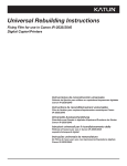
Time Clock Detail Report Modified
The Time Clock Detail Report has been modified to clearly indicate
which time cards have been adjusted. A series of asterisks, (*****), will
appear in the ‘Time’ column when the time card has been adjusted, as
seen on the next page.
MD0007-039
August 11, 2009
Page 46 of 62
Version 2.8
MICROS e7 Version 2.8
What’s New
========================================
MICROS CAFE
7031 Columbia Rd
Time Clock Detail Report
Scope:
System
Business Date:
Wed 07/29/2009
Taken From:
CASHIER
Generated:
Wed 07/29/2009 09:03PM
========================================
========================================
10006 BARBER, BOB
========================================
Job
Date
Time
---------------------------------------1
SERVER
In
Out
(*****)
07/29/2009
11:21AM
07/29/2009
06:30PM
-Manager Clock Out
SERVER
Hours
Pay
---------------------------------------Reg
7.160
14.32
Ovt
0.000
0.00
Viewing the Time Clock Adjustment Detail Report
1. Navigate to the Reports module.
2. Under the ‘Labor Reports’ section, select the Time Clock Adjustment
Detail Report.
3. Select the parameters for the report:
Version 2.8
MD0007-039
August 11, 2009
Page 47 of 62
MICROS e7 Version 2.8
What’s New
•
Select Date Range- Choose from Today, Yesterday, This Pay
Period, Last Pay Period, or By Business Date.
•
From-
•
•
MD0007-039
August 11, 2009
Page 48 of 62
•
If selecting a date range other than ‘By Business Date,’ this
field will automatically populate with the beginning date for
the range. The dates appear gray and cannot be edited.
•
If the ‘By Business Date’ is selected as the date range, the text
in this field becomes black and can be edited by selecting the
drop-down. Select the desired start date.
To•
If selecting a date range other than ‘By Business Date,’ this
field will automatically populate with the end date for the
range. The dates appear gray and cannot be edited.
•
If the ‘By Business Date’ is selected as the date range, the text
in this field becomes black and can be edited by selecting the
drop-down. Select the desired end date.
Select Range- Select the employees to be included in the report
by using the ‘Start’ and ‘End’ drop-downs. The report will
include the employees whose object number are in between those
of the selected ‘Start’ and ‘End’ employees. For example, if
‘10006 Barber Bob’ is selected as the start of the range and
‘10015 Carver Brent’ is selected as the end of the range,
employees with object numbers between 10006 and 10015 will be
included in the report if adjustments have been made.
•
Start- Select the employee with the lowest object number to
be included in the report.
•
End- Select the employee with the highest object number to
be included in the report.
Version 2.8
MICROS e7 Version 2.8
What’s New
4. Click [Reports] to preview the report. This report can also be printed
or saved to a file using the corresponding buttons.
Setup
Microsoft Visual C++ 2008 SP1 Runtime Libraries Installed
SCR# 2927
With this release, MICROS e7 will install an updated version of the
Microsoft Visual C++ Runtime libraries, version 2008 Service Pack 1
Version 2.8
MD0007-039
August 11, 2009
Page 49 of 62
MICROS e7 Version 2.8
What’s New
Utilities
Remote Support Introduced for Workstation Only Sites
SCR# 2943
MICROS e7 has added remote support for sites without a PC. Now,
Athena® (Odyssey software) can be enabled for remote support at
workstation only sites.
To support the Athena software, a new command button has been added
that starts or stops the service. Once this command button is pressed, the
workstation will prompt the user to confirm remote control access is
allowed. For the command button configuration procedures, see
“Configuring the Touchscreen Command Button” on page 51.
Important!
Athena is NOT installed with MICROS e7.
What is Athena®?
Odyssey Software Athena is a powerful device management engine (also
referred to as a device client or agent) that includes an integrated Web
server and Web services engine, available for all devices running
Microsoft® Windows® CE and 32-bit Operating Systems.
Athena is designed around open Internet standards and protocols such as
HTTP/S, HTML, and SOAP, and is extensible through the use of services
or plug-ins. It provides all of the essential elements for effective device
management, such as: device discovery, hardware and software inventory
collection, file management and remote control.
Athena enables organizations of all sizes to easily manage and support
MICROS Systems, Inc. Windows CE devices.
Athena enables your IT staff to reduce support costs, improve application
availability, enhance employee productivity, and optimize technical
support delivery.
For more information, please contact MICROS Hardware Services.
MD0007-039
August 11, 2009
Page 50 of 62
Version 2.8
MICROS e7 Version 2.8
What’s New
Programming the MICROS e7 Configurator User Privilege
The new remote support functionality requires the MICROS e7 user to
have the new ‘Use Remote Access’ privilege enabled. To enable this
privilege, follow the steps below:
1. Navigate to the MICROS e7 Configurator.
2. Select the Jobs form by selecting ‘Jobs’ from the top left drop-down.
3. Select the desired job.
4. Navigate to the Privileges tab.
5. Within the Module Access group, check the ‘Use Remote Access’
checkbox. Signed in employees with this privilege can start and stop
Athena.
6. Click the [Save] icon.
Configuring the Touchscreen Command Button
1. Navigate to the MICROS e7 Configurator.
2. Select Touchscreens from the drop-down on the top left.
3. Select the desired touchscreen from the ‘Touchscreen’ drop-down.
4. Click [New Button]. The new button will appear on the touchscreen.
5. Move the button to the desired location on the touchscreen.
6. From the ‘Function’ drop-down, under the ‘Non-Sales’ section, select
the new ‘Remote Access’ command button.
7. Program any the remaining fields per your site’s administrator.
8. Click the [Save] icon.
Version 2.8
MD0007-039
August 11, 2009
Page 51 of 62
MICROS e7 Version 2.8
What’s Enhanced
MICROS e7 Version 2.8
What’s Enhanced
An enhancement is defined as a change made to improve or extend the
functionality of the current MICROS e7 software. To qualify as an
enhancement, the change must satisfy the following criteria:
The basic feature or functionality already exists in the previous
release of the software.
The change adds to or extends the current process. This differs from a
revision (i.e., a bug fix) which corrects a problem not caught in the
previous release of the software.
Enhancements
Summarized
The table below summarizes the enhancements included in this version.
Module
Install
Enhancements
Detailed
Feature
CR ID
Page
The MICROS e7 PC Install
Restores the Database Backup if no
Database is Present
N/A
52
Install
The MICROS e7 PC Install Restores the Database Backup if
no Database is Present
SCR# 2942
With this release, the MICROS e7 PC install program has been enhanced
so that the database backup (DBBackup) is restored if no database exists.
MD0007-039
August 11, 2009
Page 52 of 62
Version 2.8
MICROS e7 Version 2.8
What’s Enhanced
When performing a MICROS e7 software upgrade, the install program
will operate the same as previous versions. When performing a new
installation of MICROS e7, the enhanced PC install program allows the
user to copy a backup of the database into the DbBackups directory
(\micros\e7\DBbackups). Previously, if e7 started and no database was
present, a shell database was created. The user then had to program the
database in the Configurator.
If MICROS e7 v. 2.8 starts with no database present and no backup in the
DbBackups directory (\micros\e7\DBbackups), it operates as in previous
versions. Now, if MICROS e7 v. 2.8 starts with no database present, but
the DbBackups directory contains backup.001.gz and/or backup.002.gz
file(s), it restores whichever file is most recent.
Enhanced MICROS e7 Setup Process
To use this functionality, during the MICROS e7 setup process, select the
‘Install your custom database as part of setup’ option bit, as seen below.
Click [Next].
Version 2.8
MD0007-039
August 11, 2009
Page 53 of 62
MICROS e7 Version 2.8
What’s Enhanced
Type the full path of the backup file you wish to import or use the
[Browse] button to search for the desired file. Note that the path and file
name are case sensitive. Click [Next]. Continue the MICROS e7 setup
process.
MD0007-039
August 11, 2009
Page 54 of 62
Version 2.8
MICROS e7 Version 2.8
What’s Revised
MICROS e7 Version 2.8
What’s Revised
A revision is defined as a correction made to any existing form, feature,
or function currently resident in the MICROS e7 product. To qualify as a
revision, the change must satisfy the following criteria:
The basic form, feature, or functionality must be part of the previous
version of the software.
The change must replace the current item or remove it from the
application.
Revisions
Summarized
The table below summarizes the revisions included in this version.
Module
Feature
CR ID
Page
Credit Card
Batch
The Credit Card Batch could Fail
to Create and Cause the Business
Date to not Increment
The Credit Card Batch could Fail
to Create if the Batching Node and
mymicros.net Host Node were on
the Same Workstation
Workstation Credit Card Batching
Node Restart Performance
Improved
ManagerVoidTransaction.txt File
no longer Included in the
TIFExport
27390
56
26070
57
27135
57
26477
58
Database
Export
Version 2.8
MD0007-039
August 11, 2009
Page 55 of 62
MICROS e7 Version 2.8
What’s Revised
Revisions
Detailed
Module
Feature
CR ID
Page
MICROS e7
Operations
MICROS e7 Unexpectedly Exited
with an Unhandled Exception
After Cancelling when Prompted
to Enter a Table Number or Guest
Count
Printed Modifiers Rung After
Non-Printing Modifiers do not
Print
Canceling a Check with an
Automatic Service Charge
Removes the Service Charge
Memory Leak Caused
Workstations to run out of
Memory
Priced Condiments did not
Always Print on the Guest Check
27193
59
25553
59
25981
61
61
61
Credit Card Batch
The Credit Card Batch could Fail to Create and Cause the
Business Date to not Increment
SCR# 2966
CR ID# 27390
Previously, under certain circumstances, the credit card batch failed to
create, causing the business date to not increment. This issue occurred
when the check detail file did not exist. This has been corrected.
MD0007-039
August 11, 2009
Page 56 of 62
Version 2.8
MICROS e7 Version 2.8
What’s Revised
The Credit Card Batch could Fail to Create if the Batching
Node and mymicros.net Host Node were on the Same
Workstation
SCR# 2887
CR ID# 26070
Previously, it was possible for the credit card batch to fail to create if the
batching node and mymicros.net host were on the same workstation. This
issue occurred when the batch process began and MICROS e7 attempted
to retrieve the checks from the closedcheckoverheads.bin file on each
workstation. If mymicros.net attempted to process the 15 minute
transaction at the same time, the batch failed to create. This has been
corrected.
Database
Workstation Credit Card Batching Node Restart
Performance Improved
SCR# 2946
CR ID# 27135
Previously, when the workstation was the credit card batching node and
the maximum number of batches to keep (90) was configured, it could
have taken 10 minutes or more for MICROS e7 to restart on the node that
was batching. MICROS e7 could not be used during this time. This has
been corrected.
Version 2.8
MD0007-039
August 11, 2009
Page 57 of 62
MICROS e7 Version 2.8
What’s Revised
Export
ManagerVoidTransaction.txt File no longer Included in the
TIFExport
SCR# 2906
CR ID# 26477
Previously, the ManagerVoidTransaction.txt file in the TIFExport did not
populate with any information. This file has been removed from the
TIFExport as it is not used by MICROS e7.
Manger void information can be obtained from the export files within the
MenuItemTransDetail.txt folder. When a void is conducted, the
authorizing employee sequence as well as the ReasonDefSeq are
recorded from the transaction. These sequences would need to match the
EmplSeq and the EmployeeDefs files in the ReasonDef file to see who
authorized the void and why.
For example: Below is the void entry from theMenuItemTransDetail.txt
file. The 151 in red is the EmployeeSeq of the person who authorized the
void. The 6 in red is the ReasonDefSeq.
3,4/29/2009,04/30/2009 10:52:29AM,04/30/2009 10:52:36AM,130,1,1.25,0.00,300,151,1,1,1,True,False,False,False,False,False,False,30,6
The line below is from the EmployeeDEfs.txt file. The 151 in red
corresponds to the manager.
151,10026,11:"MGMT",XXX,"",XXX,"MICHAEL","MANDELLA","","","","","
",1/1/1920 12:00:00
AM,"","T1",1:"SYSTEM",0,True,True,True,False,1004:"MANAGER"
The line below is from the ReasonDef.txt file. The 6 in red is the seq
number of the Reason code that was used for the void.
6,5,"OUT OF MENU
ITEM","",False,True,False,False,True,False,False,False
MD0007-039
August 11, 2009
Page 58 of 62
Version 2.8
MICROS e7 Version 2.8
What’s Revised
MICROS e7 Operations
MICROS e7 Unexpectedly Exited with an Unhandled
Exception After Cancelling when Prompted to Enter a Table
Number or Guest Count
SCR# 2947
CR ID# 27193
Previously, in a fast transaction environment, when a user was required to
enter a table number and guest count, the MICROS e7 application would
unexpectedly exit when the user selected [Cancel] after being prompted
for the guest count. If the user selected [No] to the prompt to cancel the
transaction, the price of the first menu item incorrectly rang in as $0.00.
Now, when the user selects [Cancel] when being prompted to enter the
table number or guest count, a check will not be created and the user will
be returned to the configured ‘default’ touchscreen. Also, the window
that prompts the user to confirm the cancellation has been removed.
Printed Modifiers Rung After Non-Printing Modifiers do not
Print
SCR# 2854
CR ID# 25553
Previously, when ringing in a menu item with a modifier, such as a
‘Pound of Wings, Hot,’ after pressing the [Modify Menu Item (Insert
Condiment)] key to substitute the parent menu item (i.e, substituting
Chicken Tenders for Wings), only the parent item printed. For example,
the ‘Pound of Wings’ prints but not ‘Hot’ or ‘Sub Chix Tender.’
This issue occurred because of incorrect operational procedures. When
attempting to modify the parent item, ‘Pound of Wings,’ the modification
was done to the modifier, ‘Hot’ instead. For example, the incorrect
procedure was:
1. Ring in ‘Pound of Wings’
2. Select the modifier, ‘Hot’
Version 2.8
MD0007-039
August 11, 2009
Page 59 of 62
MICROS e7 Version 2.8
What’s Revised
3. Press the [Modify Menu Item (Insert Condiment)] button
4. Select ‘Sub Chix Tender’
After following the procedure above, the items will print as follows:
1 Pound of Wings
Hot
Sub Chix Tender
The ‘Sub Chix Tender’ modifier modified the non-printing modifier,
‘Hot.’ Since the ‘Hot’ modifier is not configured to print any modifiers to
it, the menu item does not print either (ignoring the fact that it is priced).
The correct procedure is:
1. Ring ‘Pound of Wings’
2. Select the modifier, such as ‘Hot’
3. Highlight ‘Pound of Wings’
4. Press the [Modify Menu Item (Insert Condiment)] button
5. Select ‘Sub Chix Tender’
After following the procedure above, the menu items will print as:
1 Pound of Wings
Hot
Sub Chix Tender
In this case, the ‘Sub Chix Tender’ modifier modifies the parent item,
‘Pound of Wings’ and all items print as expected.
MD0007-039
August 11, 2009
Page 60 of 62
Version 2.8
MICROS e7 Version 2.8
What’s Revised
Canceling a Check with an Automatic Service Charge
Removes the Service Charge
SCR# 2877
CR ID# 25981
Previously, when a check with an automatic service charge was service
totalled, picked up, and then [Cancel] is selected, the automatic service
charge no longer appears on the check after the check is picked up. This
has been corrected.
Memory Leak Caused Workstations to run out of Memory
SCR# 2926
Previously, under certain circumstances, a memory leak caused
workstations to run out of memory. This issue affected WS4s, WS4 LXs,
and WS5s. This has been corrected.
Priced Condiments did not Always Print on the Guest Check
SCR# 2992
Previously, it was possible to program a priced condiment so that it did
not print on the guest check. The resulting guest check was ‘out of
balance’ because the priced condiment added to the check total but did
not display in the check detail.
Now, priced menu items and condiments will always print on the guest
check so that customers can easily determine how the check total was
calculated.
Any condiment modified by a priced condiment will also always print on
the guest check. For example, a customer orders a Steak Salad with
French dressing. The French dressing is a priced condiment with a cost of
$2.00. Because the French dressing is a priced condiment, both ‘Salad’
and ‘French’ will print on the guest check, as seen below:
STEAK
10.00
SALAD
FRENCH 2.00
Version 2.8
MD0007-039
August 11, 2009
Page 61 of 62
MICROS e7 Version 2.8
What’s Revised
This rule only applies to condiments that are not programmed to roll up
into the parent menu item price. For example, if the French dressing was
programmed to roll up, the guest check would print:
STEAK
12.00
If the French dressing was not a priced condiment, neither ‘French’ or
‘Salad’ would print on the guest check.
MD0007-039
August 11, 2009
Page 62 of 62
Version 2.8