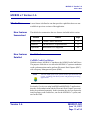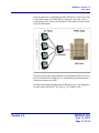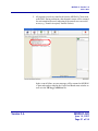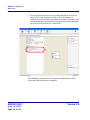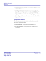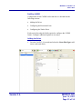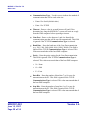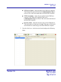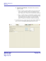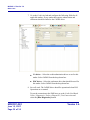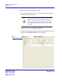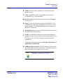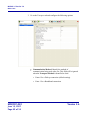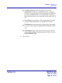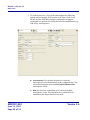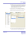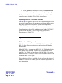
1
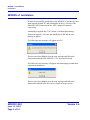
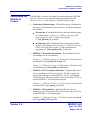
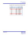
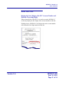
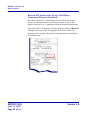
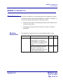
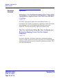
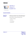
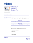
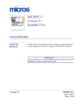
MICROS e7 Version 2.6 ReadMe First General Information About This Document ReadMe First is an introduction to the new features, enhancements and revisions added in the Version 2.6 release of the MICROS e7 product. Product information is divided into the following sections: MICROS e7 Installation What’s New What’s Enhanced What’s Revised Version 2.6 MD0007-020 June 14, 2007 Page 1 of 54 General Information Declarations Declarations Warranties Although the best efforts are made to ensure that the information in this manual is complete and correct, MICROS Systems, Inc. makes no warranty of any kind with regard to this material, including but not limited to the implied warranties of marketability and fitness for a particular purpose. Information in this manual is subject to change without notice. No part of this manual may be reproduced or transmitted in any form or by any means, electronic or mechanical, including photocopying, recording, or information recording and retrieval systems, for any purpose other than for personal use, without the express written permission of MICROS Systems, Inc. MICROS Systems, Inc. shall not be liable for errors contained herein or for incidental or consequential damages in connection with the furnishing, performance, or use of this manual. Trademarks Framemaker is a registered trademark of Adobe Corporation. Microsoft and Windows are registered trademarks of Microsoft Corporation in the United States and/or other countries. All other trademarks are the property of their respective owners. MD0007-020 June 14, 2007 Page 2 of 54 Version 2.6 General Information Introduction Introduction MICROS e7 is a robust point-of-sale solution, with the high quality, reliable and extensive features that the marketplace has grown to expect from MICROS. All of this has been packaged specifically for the independent restaurateur. MICROS e7 is a complete solution that utilizes the revolutionary MICROS Workstation POS terminal platform and MICROS' 25 plus years of industry leading software solutions. The MICROS e7 user interface offers an intuitive, user-friendly touchscreen design that takes advantage of color, font, and an efficient screen layout to guide servers through the order entry process. The simplicity of the design reduces training time, improves speed of service to the customer, and lowers error rates for daily operations. For more information about the MICROS e7 product, refer to the following resources: Marketing Overview - This manual provides information regarding MICROS, the hospitality industry, features and benefits, sample reports, and a proposed return on investment for MICROS e7. This document is available for download from the MICROS website e7 | Marketing | e7 Marketing Overview. Getting Started - This manual provides site survey, installation, and configuration information to help you get your MICROS e7 site up and running. This document is available for download from the MICROS website e7 | e7 [Release Version] | Documentation | e7 Getting Started. User’s Manual - This manual provides information on how to use the MICROS e7 System, including POS Operations, Manager Procedures, Credit Card Batch, and Reporting. This document is available for download on the MICROS website e7 | e7 [Release Version] | Documentation | e7 User’s Manual. Version 2.6 MD0007-020 June 14, 2007 Page 3 of 54 MICROS e7 Installation Introduction MICROS e7 Installation In order to successfully install and use the MICROS e7 product, the user must upgrade both the PC and workstations to the 2.0 Version of the Microsoft .NET Framework or the .NET Compact Framework respectively. Attempting to upgrade the e7 to Version 2.6 without performing a framework upgrade, will cause the installation to fail and an error message to appear. The following error message will appear on a PC: If this occurs select [Ok] to clear the error message and follow the instructions outlined in the MICROS e7 PC Installation section. The following error message will appear when attempting a stand-alone workstation installation: If this occurs select [Ok] to clear the error message and follow the instructions outlined in the Workstation Platform Image section. MD0007-020 June 14, 2007 Page 4 of 54 Version 2.6 MICROS e7 Installation Downloading the MICROS e7 Product Downloading the MICROS e7 Product The MICROS e7 product is available for download from the MICROS Web Site. There are several download choices available from the Member Services | Product Support | MICROS Products page: Workstation Platform Image - The platform image will depend on the type(s) of workstation(s) in use at the site. The following images are available: Workstation 4. Download this file to extract the platform image for a Workstation 4. Use the e7 | e7 [Release Version] | WS4 Platform Software (GR 2.3) link to download the e7_ws4_platform_15_1.exe file. Workstation 4 LX. Download this file to extract the platform image for a Workstation 4 LX. Use the e7 | e7 [Release Version] | WS4 LX Platform Software (RC 2.3) link to download the appropriate e7_ws4lx_platform_RC_2_3.exe file. MICROS e7 Workstation Installation - Download this file if you are installing only to a workstation. Use the e7 | e7 [Release Version] | e7 Workstation 4 Software link to download the e7_ws4_build_2.6.47.0.exe file. Use the e7 | e7 [Release Version] | e7 Workstation 4 LX Software link to download the e7_ws4lx_build_2.6.47.0.exe file. MICROS e7 PC Prerequisites Installation - Download this file if you are installing to a PC for the first time. This file contains any prerequisites necessary to run MICROS e7 on a PC, including the .NET framework. The extracted files can be used to burn a CD or to run the MICROS e7 PC Prerequisites program. Use the e7 | e7 [Release Version] | e7 PC Pre-requisite Software link to download the e7_pc_prereq_2_6.exe file. MICROS e7 PC Installation - Download this file if you are installing to a PC. The extracted files can be used to burn a CD or to run the MICROS e7 PC Setup program. Use the e7 | e7 [Release Version] | e7 PC Software link to download the e7_pc_build_2.6.47.0.exe file. Version 2.6 MD0007-020 June 14, 2007 Page 5 of 54 MICROS e7 Installation Downloading the MICROS e7 Product Workstation Platform Image The platform image and the installation instructions will vary based on the workstation(s) being used at the site. This section is divided as follows, refer to the appropriate instructions for your workstation version. Workstation 4 Workstation 4 LX Workstation 4 Use these instructions to install the Platform Image on a Workstation 4. These steps may also be used to install another CE language platform, such as Chinese, Japanese, or Korean. The MICROS e7 software will not be installed as part of these instructions. A PC or laptop is required to extract the zip (.exe) file and copy the extracted files to the appropriate transfer media, such as a USB thumb drive. 1. Copy the e7_ws4_platform_15_1.exe file from the MICROS Web Site to a temporary directory on the PC. 2. Double-click on e7_ws4_platform_15_1.exe to extract the MICROS e7 files. 3. Enter a directory location where the MICROS e7 files will be extracted (i.e., C:\wsImage). 4. Click on Unzip. 5. Click on Close. 6. Copy the directory from Step 3 (i.e., C:\wsImage) to a USB thumb drive. 7. Attach the USB thumb drive to the USB slot on the back of the Workstation 4. 8. Open Windows Explorer on the Workstation. MD0007-020 June 14, 2007 Page 6 of 54 Version 2.6 MICROS e7 Installation Downloading the MICROS e7 Product 9. Locate the MICROS e7 software directory (i.e., C:\wsImage) on the USB thumb drive. The USB thumb drive should appear in Explorer as \Hard Disk. The following two sub-directories should be available: ..\Standalone CAL Upgrade to 1.1.3.54. ..\Standalone Eng Platform 15.1 10. From the ..\Standalone CAL Upgrade to 1.1.3.54 directory, run Setup.exe to upgrade the CAL client software on the workstation. Note Make sure that each workstation has at least 25 MB of free compact flash space before installing the software on the workstation. 11. From the ..\Standalone Eng Platform 15.1 directory, run Setup.exe to install the 15.1 platform. CAL installs the Windows CE image and reboots the workstation. Workstation 4 LX Use these instructions to install the Platform Image on a Workstation 4 LX. These steps may also be used to install another CE language platform, such as Chinese, Japanese, or Korean. The MICROS e7 software will not be installed as part of these instructions. A PC or laptop is required to extract the zip (.exe) file and copy the extracted files to the appropriate transfer media, such as a USB thumb drive. 1. Copy the e7_ws4lx_platform_RC_2_3.exe file from the MICROS Web Site to a temporary directory on the PC. 2. Double-click on e7_ws4lx_platform_RC_2_3.exe to extract the MICROS e7 files. 3. Enter a directory location where the MICROS e7 files will be extracted (i.e., C:\wsImage). Version 2.6 MD0007-020 June 14, 2007 Page 7 of 54 MICROS e7 Installation Downloading the MICROS e7 Product 4. Click on Unzip. 5. Click on Close. 6. Copy the directory from Step 3 (i.e., C:\wsImage) to a USB thumb drive. 7. Attach the USB thumb drive to the USB slot on the back of the Workstation 4 LX. 8. Open Windows Explorer on the Workstation. 9. Locate the MICROS e7 software directory (i.e., C:\wsImage) on the USB thumb drive. The USB thumb drive should appear in Explorer as \Hard Disk. The following three sub-directories should be available: ..\Standalone BIOS Update ..\Standalone CAL Upgrade to 6.1.3.67 ..\Standalone Eng Platform RC 2.3 10. From the ..\Standalone BIOS Update directory, run Setup.exe to upgrade BIOS on the workstation. Note Make sure that each workstation has at least 25 MB of free compact flash space before installing the software on the workstation. 11. From the ..\Standalone CAL Upgrade to 6.1.3.67 directory, run Setup.exe to upgrade the CAL client software on the workstation. 12. From the ..\Standalone Eng Platform 2.3 directory, run Setup.exe to install the 2.3 platform. CAL installs the Windows CE image and reboots the workstation. MD0007-020 June 14, 2007 Page 8 of 54 Version 2.6 MICROS e7 Installation Downloading the MICROS e7 Product MICROS e7 Workstation Installation Use these instructions to install the MICROS e7 software on a Workstation that has the appropriate Windows CE operating system image already installed. A PC or laptop is required to extract the zip file and copy the extracted files to the appropriate transfer media, such as a USB thumb drive. The zip file will vary depending on workstation version being used at the site. This section is divided as follows, refer to the appropriate instructions for your workstation version. Workstation 4 Workstation 4 LX Workstation 4 1. Copy the e7_ws4_build_2.6.47.0.exe file from the MICROS Web Site to a temporary directory on the PC. 2. Double-click on e7_ws4_build_2.6.47.0.exe to extract the MICROS e7 files. 3. Enter a directory location where the MICROS e7 files will be extracted. (i.e. C:\e7Software) 4. Click on Unzip. 5. Click on Close. 6. Copy the directory from Step 3 (i.e. C:\e7Software) to a USB thumb drive. 7. Attach the USB thumb drive to the USB slot on the back of the workstation. 8. Open Windows Explorer on the workstation. 9. Locate the MICROS e7 software directory (i.e. C:\e7Software) on the USB thumb drive. The USB thumb drive should appear in Explorer as \Hard Disk. Version 2.6 MD0007-020 June 14, 2007 Page 9 of 54 MICROS e7 Installation Downloading the MICROS e7 Product 10. Run Setup.exe. CAL installs the MICROS e7 software and reboots the workstation. Workstation 4 LX 1. Copy the appropriate e7_ws4lx_build_2.6.47.0.exe file from the MICROS Web Site to a temporary directory on the PC. 2. Double-click on e7_ws4lx_build_2.6.47.0.exe to extract the MICROS e7 files. 3. Enter a directory location where the MICROS e7 files will be extracted. (i.e. C:\e7Software) 4. Click on Unzip. 5. Click on Close. 6. Copy the directory from Step 3 (i.e. C:\e7Software) to a USB thumb drive. 7. Attach the USB thumb drive to the USB slot on the back of the workstation. 8. Open Windows Explorer on the workstation. 9. Locate the MICROS e7 software directory (i.e. C:\e7Software) on the USB thumb drive. The USB thumb drive should appear in Explorer as \Hard Disk. 10. Run Setup.exe. CAL installs the MICROS e7 software and reboots the workstation. MD0007-020 June 14, 2007 Page 10 of 54 Version 2.6 MICROS e7 Installation Downloading the MICROS e7 Product MICROS e7 PC Installation With MICROS e7, a PC can be setup to run the MICROS e7 ReportsPlus, Configurator, and Credit Cards modules. To use these applications on a PC, the .NET framework (Version 2.0 or higher) must be installed using the e7 PC Prerequisites installation and MICROS e7 software must be installed using the MICROS e7 PC Setup installation. Optionally, the PC may be configured to be a CAL server for the MICROS e7 site, so that it can be used to update the workstations with the MICROS e7 workstation software. Note The .NET framework (Version 2.0 or higher) must be installed on the PC prior to running the MICROS e7 PC setup program. Use the e7_pc_prereq_2_6.exe file that can be downloaded from the MICROS Web Site to install the .NET framework. Use these instructions to extract the PC Prerequisites zip (.exe) file and install the extracted files to a PC. Version 2.6 MD0007-020 June 14, 2007 Page 11 of 54 MICROS e7 Installation Downloading the MICROS e7 Product Extracting the MICROS e7 PC Prerequisite Files 1. Copy the e7_pc_prereq_2.6.exe file from the MICROS Web Site to a temporary directory on the PC. 2. Double-click on e7_pc_prereq_2.6.exe to extract the files. 3. Enter a directory location where the MICROS e7 files will be extracted. (i.e. C:\e7Prereq) 4. Click on Unzip. 5. Click on Close. Installing the MICROS e7 Prerequisite Files to a PC 1. Open Windows Explorer on the PC. 2. Locate the MICROS e7 prerequisites directory (i.e. C:\e7Prereq) that you extracted in the previous steps. 3. Run e7PreReqs.exe. 4. The necessary files are installed. This may take a few minutes. Extracting the MICROS e7 PC Setup Files Use these instructions to extract the PC Setup zip (.exe) file and install the extracted files to a PC. 1. Copy the e7_pc_build_2.6.47.0.exe file from the MICROS Web Site to a temporary directory on the PC. 2. Double-click on e7_pc_build_2.6.47.0.exe to extract the MICROS e7 files. 3. Enter a directory location where the MICROS e7 files will be extracted. (i.e. C:\e7CD) 4. Click on Unzip. MD0007-020 June 14, 2007 Page 12 of 54 Version 2.6 MICROS e7 Installation Downloading the MICROS e7 Product 5. Click on Close. Note The MICROS e7 installation can be started from the directory where you extracted files in these previous steps (i.e. C:\e7CD) using the instructions below. or These extracted MICROS e7 files can be burned onto a CD. Then, e7PcSetup.exe can be executed to start the product installation. Installing the MICROS e7 PC Setup Files to a PC Note Once the CAL software is installed on the PC, the system will automatically upgrade each workstation. Make sure that each workstation has at least 25 MB of free compact flash space before installing the software on the PC. 1. Open Windows Explorer on the PC. 2. Locate the MICROS e7 software directory (i.e., C:\e7CD) that you extracted in the previous steps. 3. Run e7PCSetup.exe. 4. Click [Next] from the MICROS e7 Setup Welcome screen. 5. Review the End User License Agreement, click I Accept the Agreement, and click [Next]. 6. Enter the location where MICROS e7 will be installed. The default destination location is the same as the previously installed version of MICROS e7 or c:\Program Files\MICROS\e7 for a new installation. Use the Browse button to select a different destination location. Version 2.6 MD0007-020 June 14, 2007 Page 13 of 54 MICROS e7 Installation Downloading the MICROS e7 Product 7. Select the additional tasks to be performed by the MICROS e7 installation and click [Next]. The following actions will automatically be performed: Create shortcut on the desktop—Creates a desktop shortcut for the e7.exe file in the \bin folder. The name of the desktop shortcut is MICROS e7 and the default folder is the \bin folder. Create shortcut in the Start Menu—Creates a selection for MICROS e7 in Start Menu | Programs on the PC. Create shortcut in the Startup folder—Creates a shortcut in the PC’s startup folder for the e7.exe program. Install MICROS CAL Service—Installs the MICROS CAL Service on the PC. If the CAL server is already installed, this choice is greyed out. 8. Click [Finish] to begin installing MICROS e7. Note After the CAL server installation, the workstation operating system images will be automatically updated. If told to reboot the PC, please wait until all workstations have finished their CAL upgrade to MICROS e7 Version 2.6. MD0007-020 June 14, 2007 Page 14 of 54 Version 2.6 MICROS e7 Version 2.6 What’s New MICROS e7 Version 2.6 What’s New New Features Summarized A new feature is defined as one that provides capabilities that were not available in previous versions of the application. The table below summarizes the new features included in this version. Module New Features Detailed Feature Page Credit Cards CaPMS Credit Card Driver 15 Database The MICROS e7 Export Interface 35 Operations Workstation 4 LX Supported 46 Credit Cards CaPMS Credit Card Driver With this release, MICROS e7 introduces the CaPMS Credit Card Driver. The purpose of this driver is to allow the MICROS e7 system to authorize credit card transactions and to perform Electronic Draft Capture (EDC) with a Property Management System (PMS). Note The term PMS refers to the systems used to operate hotels and resorts, including front desk systems and payment processing applications. Previously, if a site was using both PMS and MICROS e7 applications, then the credit authorization and the Electronic Draft Capture processes had to be performed separately. In this situation, the site was required to install separate credit card drivers, one for the MICROS e7 system, and one for the PMS. Version 2.6 MD0007-020 June 14, 2007 Page 15 of 54 MICROS e7 Version 2.6 What’s New With the introduction of the CaPMS driver, the user can centralize credit card processing for the PMS and MICROS e7 systems, thereby making the credit card authorization and settlement process simpler and more efficient. The CaPMS driver is included in the MICROS e7 installation and can be added as a new credit card driver. Additional configuration is required to implement this feature. For more information see the Enabling CaPMS section beginning on page 25. How it Works Currently, the MICROS e7 application uses the PMS Interface to transmit data to the PMS. In the past communication was limited to inquiries regarding customer accounts and room charge posting information. The CaPMS driver utilizes this existing infrastructure to relay credit card transaction information to the PMS. The PMS interface requires that prior to installation, the user identifies a host node to transmit information between the MICROS e7 POS and the PMS. CaPMS can only be installed on a single PC or workstation in the network and does not support the use of a backup mode. MD0007-020 June 14, 2007 Page 16 of 54 Version 2.6 MICROS e7 Version 2.6 What’s New Once the host node is established, the other MICROS e7 nodes will route credit authorizations to the MICROS e7 host node. The node can be a workstation or a PC. In turn, the MICROS e7 host node will route all data to the host PMS node. The steps used to relay credit card data to the appropriate source will vary based on whether the CaPMS driver is transmitting an authorization or a settlement request to the PMS. Pertinent information regarding the CaPMS driver (e.g., error logging) is recorded in the \MICROS\e7\Etc\TIFLog_TIFCaPMS.txt file. Version 2.6 MD0007-020 June 14, 2007 Page 17 of 54 MICROS e7 Version 2.6 What’s New Credit Card Authorizations When the MICROS e7 host receives a request for an authorization, it will forward the request on to the PMS system. The PMS will then forward the request onto the credit card processor. All authorizations generated from the PMS and the MICROS e7 application will be routed through the PMS. Once the authorization is processed, the PMS system will return a response, either accepted or denied, to the MICROS e7’s host node. That response will then be forwarded to the workstation that generated the authorization request. Depending on the response received, the workstation will behave as follows: Authorization Accepted. The credit card voucher is printed and the credit authorization details are added to the guest check. Authorization Declined or Referred. The credit card voucher may or may not print based on the No voucher on decline setting on the Configurator | CA/EDC form. A message indicating the status of the authorization will display on the workstation. If a print class is configured for credit card vouchers then this message will also print on the voucher. Authorizations Awaiting Approval After the authorization is transmitted to the PMS system, the transaction remains in an intermediate state while the MICROS e7 node awaits a response. This response must occur before the CaPMS driver’s timeout limit is reached (CA/EDC | System | Timeout). If multiple CaPMS requests are transmitted at the same time from different workstations, they will be sent to the CaPMS host one at a time. MD0007-020 June 14, 2007 Page 18 of 54 Version 2.6 MICROS e7 Version 2.6 What’s New Credit Card Batching and Settlement Prior to settlement, the MICROS e7 system will maintain the complete payment records regarding the transaction including tip, authorization codes, and authorization amounts. At the time of settlement, this information will be combined into a newly created batch. At the time of settlement, the MICROS e7 system will transfer all payment records in the defined credit card batch to the PMS. As with other credit card drivers, settlement is performed using either the Credit Card Batch Utility or the Create Batch/ Settle Batch autosequences. If a failure occurs at any point during the settlement process, an error message will be returned to the MICROS e7 system with information regarding the nature of the problem. Batch settlement will occur in the order listed below. As the batch progresses through these steps, its status is listed in the results window of the Credit Card Batch Utility. Version 2.6 MD0007-020 June 14, 2007 Page 19 of 54 MICROS e7 Version 2.6 What’s New 1. Before beginning a new batch, the CaPMS driver will perform a query to verify that no other credit card batches are open on either system. If no batches are open, the driver will open a new batch. The driver will return one of the following responses to the MICROS e7 system indicating the batch status: MD0007-020 June 14, 2007 Page 20 of 54 Batch Opened. This indicates that a new batch was successfully opened. If this occurs the driver will progress to step 2. Batch Already Open. A batch is already open on the system. The message will list the batch number and value of the opened batch. If a batch is already opened, the new transaction records will post to this batch rather than opening a new one. Failure. A new batch could not be opened. Version 2.6 MICROS e7 Version 2.6 What’s New 2. All payment records are transferred from the MICROS e7 host node to the PMS. During settlement a batch transfer status will be returned for each transferred record, indicating if the transfer was successful or not (e.g., Transfer Accepted, Transfer Failure). In the event of failure, an error message will be returned to MICROS e7 host node and recorded in the Credit Card Batch status window as well as in the TIFLog_CaPMS.txt file. Version 2.6 MD0007-020 June 14, 2007 Page 21 of 54 MICROS e7 Version 2.6 What’s New 3. After all payment records are successfully transferred, the batch is closed. The Credit Card Batch Utility will list the number of transaction records and the total settlement amount for the batch. The settlement amount will include the final payment amount (including tips) for all of the MICROS e7 transactions. The CaPMS driver permits the user to perform authorizations while credit card batch settlement is in progress. MD0007-020 June 14, 2007 Page 22 of 54 Version 2.6 MICROS e7 Version 2.6 What’s New Troubleshooting As with other credit card drivers, the Credit Card Batch Utility can be used to perform the following diagnostic functions to assist with troubleshooting issues with the CaPMS driver. The following functions are available by selecting the [Diagnostic] button and clicking on the Select a Diagnostic drop down box. Once a selection is made click on the [Run Diagnostic] button to perform that function. Test Connection. Determines whether the MICROS e7 system is successfully connected to the PMS host using the configured connection parameters. Version 2.6 MD0007-020 June 14, 2007 Page 23 of 54 MICROS e7 Version 2.6 What’s New Get Version. Displays the build version number of the driver in the results window. Get Diagnostic Counters. Displays the current value for each diagnostic counter. The counters are used by the CaPMS driver for diagnostic purposes. This feature is mostly used for MICROS Support Staff to obtain additional details regarding a potential issue. Clear Diagnostic Counters. Clears the current values for all of the diagnostic counters. Communication Methods The following communication methods can be used to connect the MICROS e7 system to the PMS: Serial connection – If used, the host node must be a PC. TCP/IP connection – If used, the host node can be a PC or a workstation. MD0007-020 June 14, 2007 Page 24 of 54 Version 2.6 MICROS e7 Version 2.6 What’s New Enabling CaPMS Configuration for the CaPMS credit card driver is divided into the following sections: Adding the Driver Configuring the Restaurant Form Configuring the Tender Form Each section lists only the fields required to configure the CaPMS feature. Configure additional options as necessary. Adding the Driver 1. Go to the CA/EDC | System tab and select the Green Plus Sign to add a new credit card driver. Version 2.6 MD0007-020 June 14, 2007 Page 25 of 54 MICROS e7 Version 2.6 What’s New 2. Configure the following fields: Number –Enter an integer associated with this credit card driver. Name – Enter a unique descriptor for this driver. Driver Code – Use the drop-down box to select the CaPMS driver. All drivers that are supported by the system will be listed. Selecting this option will populate the table below. Node – Use the drop-down box to select the PC or workstation that will be hosting the CaPMS driver. This should match the node used to batch credit card transactions on the Restaurant | Credit Cards tab. Likewise, changing the node on this form must also be changed on the Restaurant | Credit Cards tab. The CaPMS driver will only be loaded on the selected node. If a serial connection is used, the node must be a PC. If TCP/IP is used then the node can be either a PC or a workstation. Show host messages – Enter a value to indicate whether the credit card processor reporting function will be active or not. • Enter a value of 0 to deactivate the credit card processor reporting function (default value). • Enter 1 to report any decline, referral, and error messages back to MICROS e7 Operations. This option will only dictate the behavior of the credit card processor, not the MICROS e7 host node. CaPMS will always generate its own message to Operations. MD0007-020 June 14, 2007 Page 26 of 54 Long UWS # – Determines how many characters are sent to the PMS host computer for the workstation number in the ID field of the message header. • Enter 0 to truncate the UWS messages to include only the last two digits (default value). • Enter 1 to configure a 9-digit message. UWS messages less than 9 numbers will be proceeded by zeros. Version 2.6 MICROS e7 Version 2.6 What’s New Version 2.6 DITB – Determines the format for transmitting authorization messages to the PMS. • Enter 0 to send the credit authorization in the standard format (default value). • Enter 1 to send the credit authorization messages with additional fields including the guest check number, payment date and time. Select 1 only after consulting with MICROS support personnel. Compatibility Mode – Determines the format used when transmitting credit authorizations and batch requests to the PMS system. • Enter 0 to transmit CA/EDC requests in MICROS e7 mode only (default value). • Enter 1 to transmit CA/EDC requests that are compatible with the 9700 Property Management System format. this option must be enabled when interfacing with the Southern Datacom (SDC) Server. Exclude Issue Number and Date – Determines when a manually entered credit card issue number and issue date will be included with the credit authorization or settlement request. • Enter 0 to include the issue number and date (default value). • Enter 1 to exclude the issue number and date. No voucher on decline – Determines whether the credit card voucher will be printed after the request for authorization has been declined or not. • Enter 0 if the credit card voucher should be printed (default value). • Enter 1 to suppress printing the voucher. MD0007-020 June 14, 2007 Page 27 of 54 MICROS e7 Version 2.6 What’s New MD0007-020 June 14, 2007 Page 28 of 54 Communications Type – Use this area to indicate the method of communication that will be used at the site. • Enter 0 for Serial (default value). • Enter 1 for TCP/IP. Timeout – Enter a value in seconds between 20 and 120 to determine how long the MICROS e7 system will wait on a reply from the PMS computer before reporting a timeout. Com Port – Enter a value between 1 and 4 to identify the communication port that will be used for transmission. This field is ignored if the TCP/IP Communications Type is selected. Baud Rate – Enter the baud rate of the Com Port transmission (e.g., 300, 1200, 2400, 4800, 9600, 19200, 38400). This field is ignored if the TCP/IP Communications Type is selected. This value must match that of the host PMS computer. Parity – Enter the parity setting for the Com Port transmission. This field is ignored if the TCP/IP Communications Type is selected. This value must match that of the host PMS computer. • N = None • O = Odd • E = Even Data Bits – Enter the number of data bits (7 or 8) to use for transmission on the PC. This field is ignored if the TCP/IP Communications Type is selected. This value must match that of the host PMS computer. Stop Bits – Enter the number of stop bits (1 or 2) to use for transmission on the PC. This field is ignored if the TCP/IP Communications Type is selected. This value must match that of the host PMS computer. Version 2.6 MICROS e7 Version 2.6 What’s New TCP Server Name – Enter the name of the PMS host computer. This field will be ignored if the Serial Communications Type is selected. This value must match that of the host PMS computer. TCP Port Number – Enter the port number for the PMS host computer. This field will be ignored if the Serial Communications Type is selected. This value must match that of the host PMS computer. Interface Name – Enter the interface name of the CaPMS driver. This can be up to 16 characters in length. This name will be used in the header for each message sent to the PMS host computer. 3. Go to the Merchant - Authorization tab and configure the following fields: Version 2.6 MD0007-020 June 14, 2007 Page 29 of 54 MICROS e7 Version 2.6 What’s New MD0007-020 June 14, 2007 Page 30 of 54 No multiple requests – Use this option to indicate if the PMS system can handle simultaneous processing of more than one authorization request. These requests will be sent from different workstations, as each workstation can only send a single authorization request at a time. • Enter 0 to send multiple requests simultaneously. • Enter 1 if the CaPMS should wait for a response from a message before attempting to send a second one. Only a single message will be processed at a time. Merchant ID – Enter a descriptor to identify the business. This is assigned by the credit card processor. Enter up to 16 characters. The name will be transmitted to the credit card processor with each authorization and settlement. Version 2.6 MICROS e7 Version 2.6 What’s New 4. Go to the Merchant - Settlement tab and configure the following fields: Version 2.6 Omit and Continue – Use this field to determine the driver’s behavior when the system encounters a non-reconciled check. • Enter 0 to stop settlement. • Enter 1 to allow PMS to decide what to do when the system encounters a non-reconciled check. This will include omitting the issue and continuing the settlement process. This option should only be set to 1 if host-based settlement is configured. MD0007-020 June 14, 2007 Page 31 of 54 MICROS e7 Version 2.6 What’s New Terminal-based Settlement – Determines when records are marked as settled. • Enter 0 to mark a record as settled as soon as it is processed via the Credit Card Batch Utility on the MICROS e7 host node. This process is referred to as terminal-based settlement. • Enter 1 to indicate that no record should be marked as settled until the entire group has been processed and the Batch Close command has been successfully received from the PMS system. This process if referred to as host-base settlement. 5. Go to the Restaurant | Credit Cards tab. Verify that the CaPMS host node is selected in the Batch credit cards on drop-down box. MD0007-020 June 14, 2007 Page 32 of 54 Version 2.6 MICROS e7 Version 2.6 What’s New 6. Go to the Tender form and highlight a credit card tender (e.g., Visa). Configure the following options on the CC Tender tab: Version 2.6 Prompt for issue number – Select this option to prompt the employee for the credit card issue number when card information is entered manually. Clear this option to suppress this prompt. Prompt for issue date –Select this option to prompt the employee to enter the credit card issue date when card information is entered manually. Clear this option to suppress this prompt. Repeat this step for all credit card tenders. MD0007-020 June 14, 2007 Page 33 of 54 MICROS e7 Version 2.6 What’s New 7. Go to the Credit Auth tab and configure the following fields for all applicable tenders. Every tender that requires authorization and settlement should be linked to the CaPMS driver. CA driver – Select the credit authorization driver to use for this tender. Select CaPMS from the drop-down box. EDC driver – Select the settlement driver that should be used for this tender. Select CaPMS from the drop-down box. 8. Save all work. The CaPMS driver should be operational when POS Operations are re-started. To test the connection to the PMS host, go to the Credit Card Batch Utility | Diagnostics | Select a Diagnostic | Test Connection and select the [Run Diagnostics] button. MD0007-020 June 14, 2007 Page 34 of 54 Version 2.6 MICROS e7 Version 2.6 What’s New Database The MICROS e7 Export Interface With this release, MICROS e7 introduces functionality that allows the store to automatically create and export a package of raw data as part of a scheduled autosequence. The MICROS e7 Export Interface will collect data for a the current business day and export it to a configurable location. The package will contain all of the data files listed below. A complete list of the exported text files can be found in the MICROS e7 Export Interface Engineering Specification Documentation, MD0007-021. Entire Database. Export all of the tables from the database. Sales totals. This includes all sales totals and reports generated via the MICROS e7 system. Transactional data. Exports all data relating to the transactions performed for the business day. Reports. All of the 22 MICROS e7 reports that can be exported are written to disk files in 40-column format. This will help with developing solutions based on the sales totals and transactional data. Raw data is compiled in the form of text (.txt) files, that are assembled and compressed into .zip file format. The .zip file package is then transmitted to either an external source, or maintained locally at the store. Once the data is sent, it can then be imported into the application of the user’s choice. Additional development work will be required by the user in order to transfer data into a third party application. See the Importing Data Into Third Party Software section on page 46 for more information. Version 2.6 MD0007-020 June 14, 2007 Page 35 of 54 MICROS e7 Version 2.6 What’s New The Export interface provides all the data necessary for building or interfacing to sales reporting and information management tools. The following is a list of some of the valuable ways that an export package can be used: Stores can export data to a central location at the close of business automatically, as part of their nightly autosequence. The user can monitor the store’s transactional and sales data remotely. Additional development is required by the user in order to transfer data to a third party application. The compressed .zip format can be accessed easily for future reference. How it Works Once configured, the Export interface will assemble a package of data and export it as part of an autosequence (e.g., the End of Night Autosequence). When the Update Bus Date autosequence action is executed, the MICROS e7 system will send the information to the designated location. At this time, the following transfer methods are available: Files transferred locally. This transfer method allows the user to maintain a copy of the transferred files on their local machine. This method works best when the transfer node is a PC. File Transfer Protocol (FTP). With this transfer method, files are exported to a centrally accessible location (e.g., a mapped network drive) where they can be accessed by a third party. When a package is transferred, a copy of the package is also sent to the following directory on the MICROS e7 host node: \MICROS\e7\TIFExports\TIFExport\(InterfaceObjNumber) If multiple export interfaces have been created then each will be numbered based on the interface record’s object number (e.g., \TIFExport\1 and \TIFExport\2). MD0007-020 June 14, 2007 Page 36 of 54 Version 2.6 MICROS e7 Version 2.6 What’s New The Export interface ships along with the MICROS e7 application Version 2.6 and higher. Additional configuration is required to activate this feature. Architecture Prior to implementing the Export interface, the user must decide which node will function as the host node for the export interface. This will be the node where all of the information is gathered from the other nodes, packaged, and exported to the desired location. The host node can be either a PC or a workstation. If dial-up is used at the site, the host node must have an attached dial-up modem for the Export interface to be successful. The host node must be connected to the communication method used to export data. For example, if data will be exported via a mapped network drive, then the node must be connected to that drive. During operations, the Export interface writes messages to the TIFLog_TIFExport.log file on the MICROS e7 host node. Once the raw data is exported, it is the responsibility of the third party to import the package to the appropriate application so that it can be interpreted. Enabling the MICROS e7 Export Interface Although the Export interface feature is installed with the MICROS e7 Version 2.6 software, additional configuration is required. This section outlines the steps necessary to configure this feature. Additional options may be configured as desired. Version 2.6 MD0007-020 June 14, 2007 Page 37 of 54 MICROS e7 Version 2.6 What’s New Follow these steps to configure this feature: 1. Go to the Configurator | Interfaces form and select the Green Plus Arrow to add a new interface. Note If data is to be exported to more than one location, then additional interface records should be created. For example, if a site would like to export one set of data to their corporate headquarters and export another copy to be maintained internally, 2 Export interfaces should be added. Repeat steps 1-5 for each additional interface. 2. Configure the following options. The Export configuration table will appear after the Interface Code field is configured. MD0007-020 June 14, 2007 Page 38 of 54 Version 2.6 MICROS e7 Version 2.6 What’s New Number. Select a unique number to be associated with this interface record. Name. Assign this record a unique identifier that is easily recognizable (e.g., Export Interface). Interface Code. Use the drop-down box to select the Export interface type. Node. Use the drop-down box to select the MICROS e7 host node identified at the time of installation. See the Architecture section on page 37 for additional information on selecting an MICROS e7 host node. Backup Interface. Leave this field blank. No backup interfaces should be used with this feature. Site ID. Use this field to identify the location from which the package is being sent. Be certain to enter a unique identifier (e.g., Mike Rose Cafe_015). This will appear in the name of the transport file. The default .zip file name format is (Site ID)_(Timestamp or 3 digit sequence number).zip. Number of Days to Archive. Enter the number of days to store the .zip file with all of the exported data. The default setting is 7 days. Acceptable values range from 1 to 7 days. Note Version 2.6 All files moved to the Archive directory will have “_YYMMDD” appended to the file name. MD0007-020 June 14, 2007 Page 39 of 54 MICROS e7 Version 2.6 What’s New 3. Go to the Transport tab and configure the following options: MD0007-020 June 14, 2007 Page 40 of 54 Communication Method. Identify the method of communication being used at the site. This field will be ignored when the Transport Method is identified as local. • Enter 0 for a Dial-up connection (default setting). • Enter 1 for a Broadband connection. Version 2.6 MICROS e7 Version 2.6 What’s New Version 2.6 Transport Method. Identifies the method of transporting the export data. Enter one of the following values: • Enter 0 to indicate that the package will be kept locally (default value). Selecting this value will cause the system to ignore fields that configure exporting to an outside source. • Enter 1 to indicate that the FTP export method will be used. This will export the package to an FTP server. The FTP server name is configured in the Server Name field. Timestamp Transport File Name. Enabling this option will cause a timestamp to append the transport file name (e.g., SiteID_MMDDYY.zip) (default behavior). When disabled, a three digit sequence number should append the transport file name (e.g., SiteID_001.zip). Outside Phone Line Access Code. Enter the numbers that should be dialed in order to access an outside phone line (e.g., dial 9 to dial outside of the company). Leave this field blank if additional numbers do not need to be dialed. Tone or Pulse Dialing. For a dial up connection, identify whether a tone or a pulse is used to dial. • Enter 0 to identify tone. • Enter 1 to identify pulse. Location Country Code. Enter the country code that identifies the location of the store sending the transport file. Valid values range from 1 to 999. The default value is 1 for the United States. Location Area Code. Enter the area code of the location where the call originates when using a dial up connection to transmit the export data. Dialing Country Code. Enter the country code that identifies the location of where you are calling. This will be the same as the value identified in the Location Country Code field unless an international call is being made. Valid values range from 1 to 999. The default value is 1 for the United States. MD0007-020 June 14, 2007 Page 41 of 54 MICROS e7 Version 2.6 What’s New MD0007-020 June 14, 2007 Page 42 of 54 Dialing Area Code. Enter the area code that identifies the location that you are calling. Dialing Phone Number. Enter the local phone number (the last 7 digits of a telephone number) to call when using a dial up connection to transmit the export data. Dial as Local/ Long Distance/ International. Determine the dialing pattern of a dial-up connection based on whether a local, long distance or an international call is being made. Select from one of the following values: • 0. Indicates a local area telephone number will be dialed. This includes the Area Code + Local Number. • 1. Indicates a long-distance telephone number will be dialed. This includes a 1 + Area Code + Local Number. • 2. Indicates that an international telephone number will be dialed. This includes the Country Code + Area Code + Local Number. User Name. Enter the user name that will be required for authentication if accessing a private network/ Internet Service Provider (ISP). Password. Enter the password that will be required for authentication if accessing a private network/ Internet Service Provider (ISP). Secondary User Name. Enter the user name required for authentication or to access a controlled site (e.g., a company’s FTP site). If using dial-up the user may need one user name and password to authenticate and access an ISP, and a second user name and password to access a protected resource such as an FTP site. Version 2.6 MICROS e7 Version 2.6 What’s New Secondary Password. Enter the password required for authentication or to access a controlled site (e.g., a company’s FTP site). If using dial-up the user may need one user name and password to authenticate the access an ISP, and a second user name and password to access a protected resource such as an FTP site. Server Name. Enter the name of the location where the export package is being transmitted (e.g., ftp.mikerosecafe.com). FTP Directory. Enter the directory location where the package file will be sent is usually left blank and the default path will be used. FTP Filename. Enter a name for the file being sent. This field will usually be left blank and the default name will be used (e.g., SiteID_MMDDYY.zip). 4. Save all work. Version 2.6 MD0007-020 June 14, 2007 Page 43 of 54 MICROS e7 Version 2.6 What’s New 5. Go to the Restaurant | General tab and configure the following options in the Automatic EOD section of the form. If one is not already in place, MICROS strongly recommends creating an autosequence to perform all closing duties for the establishment (e.g., End of Day Autosequence). MD0007-020 June 14, 2007 Page 44 of 54 Autosequence. Use the drop-down box to select the Autosequence to run automatically at the configured time. The selected autosequence must contain Update Business Date autosequence action. Run on. Select the workstation or PC where the nightly autosequence is run. This should be the workstation or PC identified as the Export interface host node. Version 2.6 MICROS e7 Version 2.6 What’s New Start time. Select the time when the automatic autosequence will occur to transmit the export files. MICROS recommends that you select a time when the establishment is always closed for business but before employees start to arrive in the morning. This time must be later than the Business date start time. 6. Go to the Autosequences form and highlight the autosequence selected in the Restaurant | General | Autosequence drop-down box. MICROS recommends selecting the End of Day Autosequence. Version 2.6 Go to the Action tab on the bottom-right hand side of the form and select the Green Plus Arrow to add an autosequence action. MD0007-020 June 14, 2007 Page 45 of 54 MICROS e7 Version 2.6 What’s New Use the Action drop-down box to select the Update Bus Date action. This step is required to create and export the package. The Export interface is now operational. The designated data will be exported as part of the daily End of Night Autosequence. Importing Data Into Third Party Software Once the data is exported as part of the End of Night autosequence, it is in text file format. The user can now import and process the data using a third party application of their choice. In order to accomplish this, additional development may be required. For information on the text files and data exported by the MICROS e7 system, see the MICROS e7 Export Engineering Specification Documentation, MD0007-021. Operations Workstation 4 LX Supported With this release, the Workstation 4 LX (WS4 LX) is supported. The WS4 LX offers faster processing power and more memory than the Workstation 4. When MICROS e7 is running on the WS4 LX, the Taskbar that displays at the bottom of the screen in Windows will be automatically set to AutoHide. The Taskbar will not display while MICROS e7 is running. When MICROS e7 is closed, the user will have to run the cursor over the Taskbar in order for it to display. This workstation will not be available for sale until after the release of MICROS e7 Version 2.6. Contact your MICROS sales representative for more information. MD0007-020 June 14, 2007 Page 46 of 54 Version 2.6 MICROS e7 Version 2.6 What’s Enhanced MICROS e7 Version 2.6 What’s Enhanced An enhancement is defined as a change made to improve or extend the functionality of the current MICROS e7 software. To qualify as an enhancement, the change must satisfy the following criteria: The basic feature or functionality already exists in the previous release of the software. The change adds to or extends the current process. This differs from a revision (i.e., a bug fix) which corrects a problem not caught in the previous release of the software. Enhancements Summarized The table below summarizes the enhancements included in this version. Module Feature Operations Table View Enhancement 48 Workstation 4 Taskbar Enhancement 50 Display the Last 4 Digits of the SVC Account Number and Mask the Preceeding Digits 51 Reversal Will Appear at the Top of a Chit When a Transaction Reversal is Performed 52 Stored Value Cards Version 2.6 Page MD0007-020 June 14, 2007 Page 47 of 54 MICROS e7 Version 2.6 What’s Enhanced Operations Table View Enhancement With this release, MICROS e7 has enhanced the table view display in Operations. Previously, when beginning a check by table, the user would select a table from the table view. There was no way to tell via the table view display whether a check was already open for that table. If only one open check was allowed for each table (Configurator | Restaurant | Posting | Only one group per table), and the user tried to begin a check, they would receive the following error message: Selecting [Ok] would return the user to the table view and they would have to pick another table. If multiple checks were allowed for each table the only way to know multiple checks were opened on a table was to refer to the group number on the check. MD0007-020 June 14, 2007 Page 48 of 54 Version 2.6 MICROS e7 Version 2.6 What’s Enhanced For example, if there were two open checks for table 600, the first check would display as 600-1, while the second check would display as 600-2. Version 2.6 MD0007-020 June 14, 2007 Page 49 of 54 MICROS e7 Version 2.6 What’s Enhanced MICROS e7 has enhanced the table view to automatically indicate which tables have open checks by displaying the table key in white. The number of open checks for each table will also appear on the table key. The number of open checks will automatically display in the top left corner of the table key. A table with an open check will automatically appear in white. The ability to immediately determine the tables with open checks will improve employee productivity and reduce the amount of time required to begin a check. There is no additional configuration is required. This enhancement is now system default behavior. Workstation 4 Taskbar Enhancement When MICROS e7 is running on the WS4, the Taskbar that displays at the bottom of the screen in Windows will be automatically set to AutoHide. The Taskbar will not display while MICROS e7 is running. When MICROS e7 is closed, the user will have to run the cursor over the Taskbar in order for it to display. MD0007-020 June 14, 2007 Page 50 of 54 Version 2.6 MICROS e7 Version 2.6 What’s Enhanced Stored Value Cards Display the Last 4 Digits of the SVC Account Number and Mask the Preceeding Digits When a Stored Value Card (SVC) was used as a tender, MICROS e7 would only display the last 4 digits of the account number on the chit. With this release, MICROS e7 will display the entire account number with all but the last 4 digits masked on the chit. Version 2.6 MD0007-020 June 14, 2007 Page 51 of 54 MICROS e7 Version 2.6 What’s Enhanced Reversal Will Appear at the Top of a Chit When a Transaction Reversal is Performed Previously, when an SVC transaction was reversed, the user had no visual cue to determine that a reversal had occurred except for the negative character (e.g., -) appearing in front of the transaction amount. Now, when an SVC transaction reversal is performed, the text Reversal will appear at the top of the chit, appended to the name of the SVC transaction. For example, a Reload Account transaction is now Reload Account Reversal. MD0007-020 June 14, 2007 Page 52 of 54 Version 2.6 MICROS e7 Version 2.6 What’s Revised MICROS e7 Version 2.6 What’s Revised A revision is defined as a correction made to any existing form, feature, or function currently resident in the MICROS e7 product. To qualify as a revision, the change must satisfy the following criteria: The basic form, feature, or functionality must be part of the previous version of the software. The change must replace the current item or remove it from the application. Revisions Summarized Version 2.6 The table below summarizes the revisions included in this version. Module Feature Operations Attempting to Use On Demand Printing When Combo Meal Consolidation was Applied to the Check Will Cause MICROS e7 to Close The Close Cash Drawer Dialog Box Does Not Display on a Workstation Running Version 2.0 of the Compact Framework CR ID Page N/A 54 N/A 54 MD0007-020 June 14, 2007 Page 53 of 54 MICROS e7 Version 2.6 What’s Revised Revisions Detailed Operations Attempting to Use On Demand Printing When Combo Meal Consolidation is Applied to the Check Will Cause MICROS e7 to Close CR ID#: N/A Previously, applying the combo meal consolidation feature (e.g., selecting the auto combo recognition key, repeating a combo meal order) and attempting to use On Demand Receipt Printing would cause MICROS e7 to close unexpectedly. This issue has been fixed. The Close Cash Drawer Dialog Box Does Not Display on a Workstation Running Version 2.0 of the Compact Framework CR ID#: N/A Previously, when the cash drawer opened on a workstation running Version 2.0 of the Compact Framework, the dialog box would not display indicating that the drawer must be closed for operations to resume. This issue has been corrected. MD0007-020 June 14, 2007 Page 54 of 54 Version 2.6