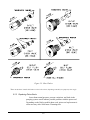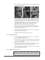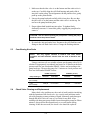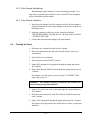
1
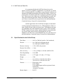
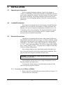
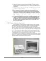
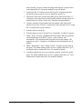
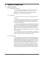
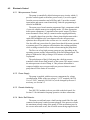
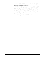
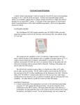
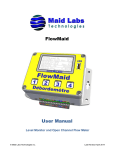
Q-Grad
Quaternary Gradient Pump
Operator’s Manual
90-2321 Rev E
Scientific Systems, Inc.
349 N Science Park Rd., State College PA 16803
Phone: 800-345-5557 / 814-234-7317 Fax: 814-238-6072
www.laballiance.com
Table of Contents
1. INTRODUCTION.......................................................................................................................................... 1-1
1.1 Description of the Q-Grad Pump..........................................................................................................................1-1
1.1.1 Pump Features ................................................................................................................................................1-1
1.1.2 Wetted Materials..............................................................................................................................................1-2
1.1.3 Self-Flushing Pump Heads ..............................................................................................................................1-2
1.1.4 Self Flush and Seal Life ...................................................................................................................................1-3
1.2 Specifications for the Q-Grad Pump....................................................................................................................1-3
2. INSTALLATION........................................................................................................................................... 2-1
2.1 Unpacking and Inspection....................................................................................................................................2-1
2.2 Location/Environment ..........................................................................................................................................2-1
2.3 Electrical Connections..........................................................................................................................................2-1
2.3.1 Converting from 115Vac to 230Vac ................................................................................................................2-1
2.3.2 Converting from 230Vac to 115Vac ................................................................................................................2-3
2.4 Solvent Preparation ..............................................................................................................................................2-4
2.4.1 Solvent Out-gassing and Sparging ..................................................................................................................2-4
2.4.2 Cavitation.........................................................................................................................................................2-5
2.4.3 Filtration ...........................................................................................................................................................2-5
2.4.4 Solvents With Harmful Effects .........................................................................................................................2-5
2.5 Instrument Installation..........................................................................................................................................2-6
2.5.1 Mobile Phase Reservoirs .................................................................................................................................2-6
2.5.2 Self-Flush Solution...........................................................................................................................................2-6
2.5.3 Self-Flush Tubing Connections ........................................................................................................................2-7
2.5.4 Inlet Tubing and Filters ....................................................................................................................................2-8
2.5.5 Outlet Tubing ...................................................................................................................................................2-8
2.5.6 Priming the Pump and the Flushing Lines .......................................................................................................2-8
2.5.7 Pressure Fault System Protection ……………………………………………………………………………………2-8
2.5.8 Long Term Pressure Calibration Accuracy ......................................................................................................2-9
2.6 Preparation for Storage or Shipping ...................................................................................................................2-9
2.6.1 Isopropanol Flush ............................................................................................................................................2-9
2.6.2 Packaging for Shipping ..................................................................................................................................2-10
3. OPERATION................................................................................................................................................ 3-1
3.1 Front Panel ............................................................................................................................................................3-1
3.1.1 Prime/Purge Valve ...........................................................................................................................................3-1
3.2 Rear Panel Remote Inputs ....................................................................................................................................3-1
3.2.1 Hardware Implementation................................................................................................................................3-2
3.2.2 Hand-Shaking ..................................................................................................................................................3-3
3.2.3 Command Interpreter.....................................................................................................................................3-3
i
3.3 Q-Grad Control Options........................................................................................................................................3-6
3.3.1 Keypad Controller ............................................................................................................................................3-6
3.3.2 PC-based Software for Pump Control..............................................................................................................3-8
3.3.3 Software Control UPgrade .............................................................................................................................3-10
3.3.4 HPLC System Control Option ........................................................................................................................3-10
4. THEORY OF OPERATION .......................................................................................................................... 4-1
4.1 Mechanical Operation ...........................................................................................................................................4-1
4.1.1 Liquid System Flow Path .................................................................................................................................4-1
4.1.2 Pump Cycle......................................................................................................................................................4-1
4.1.3 Pulse Damping.................................................................................................................................................4-1
4.2 Electronic Control .................................................................................................................................................4-2
4.2.1 Microprocessor Control ....................................................................................................................................4-2
4.2.2 Power Supply...................................................................................................................................................4-2
4.2.3 Remote Interfacing...........................................................................................................................................4-2
4.2.4 Motor Stall Detector .........................................................................................................................................4-2
5. MAINTENANCE ........................................................................................................................................... 5-1
5.1 Filter Replacement ................................................................................................................................................5-1
5.1.1 Inlet Filters .......................................................................................................................................................5-1
5.2 Changing Pump Heads .........................................................................................................................................5-1
5.2.1 Removing a Pump Head ..................................................................................................................................5-1
5.2.2 Cleaning the Pump Head Assembly.................................................................................................................5-4
5.2.3 Replacing Piston Seals ....................................................................................................................................5-6
5.2.4 Changing the Piston.........................................................................................................................................5-8
5.2.5 Replacing the Pump Head ...............................................................................................................................5-8
5.3 Conditioning New Seals........................................................................................................................................5-9
5.4 Check Valve Cleaning and Replacement.............................................................................................................5-9
5.5 Pulse Damper Replacement ...............................................................................................................................5-10
5.5.1 Removing the Pulse Damper .........................................................................................................................5-10
5.5.2 Pulse Damper Refurbishing ...........................................................................................................................5-11
5.5.3 Pulse Damper Installation ..............................................................................................................................5-11
5.6 Cleaning the Pump ..............................................................................................................................................5-11
5.7 Lubrication...........................................................................................................................................................5-12
5.8 Fuse Replacement...............................................................................................................................................5-12
5.9 Battery Replacement...........................................................................................................................................5-12
6. LIST OF REPLACEMENT PARTS .............................................................................................................. 6-1
ii
1.
INTRODUCTION
This operator’s manual contains information needed to install, operate,
and maintain the Q-Grad Quaternary Gradient Pump.
1.1
Description of the Q-Grad Pump
The Q-Grad high performance liquid chromatography (HPLC) pump is
designed to provide high-pressure quaternary gradients for HPLC
applications. Four pumps in a single cabinet are controlled with a keypad
module or a PC with supporting software.
The flow rate of each head on a Q-Grad pump fitted with standard
5 mL pump heads can be set in 0.001 mL increments from 0.001 to 5.000
mL/min. Pump heads are available in type 316 stainless steel or
biocompatible (metal-free) PEEK™.
The low pulsation flow produced by the reciprocating, single-piston
pumps are achieved by using an advanced rapid-refill cam design,
programmed stepper motor acceleration, and an internal pulse damper.
1.1.1 Pump Features
The Q-Grad Pump:
• Features four Bioclean or type 316 stainless steel pump heads
independently controlled for accurate gradients.
•
Incorporates a diaphragm-type pulse damper which reduces
pulsation in the system by as much as 90% and acts as a gradient
mixer.
•
Includes an isolated pressure transducer (i.e., the transducer adds
no dead volume).
•
Automatically turns the pump OFF if the system pressure exceeds
the maximum pressure limit determined by the pump head type
(6000 psi for stainless steel pump heads; 5000 psi for PEEK™
pump heads). The operator may program upper and lower pressure
limits within the maximum range set by the pump head type.
•
Integrated prime/purge valve.
•
Self-flushing pump heads.
•
Microprocessor advanced control.
•
Digital stepper motor design prevents flowrate drift over time and
temperature variations.
•
Back panel RS232 serial communications ports for complete
control and status monitoring of each pump head.
1-1
•
Real time system pressure reading through the RS232 port for
pump A.
1.1.2 Wetted Materials
Pump heads, check valve bodies, and tubing are made out of type 316
stainless steel or PEEK™, depending on version ordered. Other materials
common to either stainless steel or PEEK™ models are synthetic ruby and
sapphire (check valve internals and piston) and fluorocarbon (pulse
damper diaphragm).
1.1.3 Self-Flushing Pump Heads
Self-flushing pump heads provide continuous washing of the piston
surface without the inconvenience of a manual flush or gravity feed
arrangement. The self-flushing pump head uses a secondary seal and set of
check valves to create a continuous and positive flow in the area behind
the high pressure pump seal. The flushing solution washes away any
buffer salts that have precipitated onto the piston. If not removed, these
precipitates can abrade the high pressure seal and cause premature seal
failure, leakage, and can possibly damage the pump.
Figure 1-1. Self-Flushing Pump Head
1-2
1.1.4 Self Flush and Seal Life
It is recommended that the Self Flush feature be used to
improve seal life in a number of applications. In particular, (as stated
above) if pumping Buffers, Acids/Bases or any inorganic solution near
saturation, the pump should utilize the Self Flush feature. With every
piston stroke, an extremely thin film of solution is pulled back past the
seal. If this zone is dry (without use of Self Flush), then crystals will
form with continuous operation, which will ultimately damage the
seal. Water or water/IPA mix are good choices for the flush solution.
Consult the factory for specific recommendations.
Another application where Self Flush is highly recommended
is when pumping Tetrahydrofuran (a.k.a. THR, Diethylene Oxide) or
other volatile solvents such as Acetone (Note: THF and most solvents
are compatible only with all-Stainless Steel systems. THF will attack
PEEK). Volatile solvents will dry rapidly behind the seal (without the
use of Self Flush), which will dry and degrade the seal. IPA,
Methanol, water/IPA mix or water/Methanol mix are good choices for
the flush solution. Consult the factory for specific recommendations.
1.2
Specifications for the Q-Grad Pump
Flow Rates ......................0.001 to 5.000 mL/min for 5 mL/min heads,
Pressure ...........................0 to 5,000 psi for SS pump heads,
0 to 4,000 psi for PEEK™ heads
Pressure Accuracy............± 2% of full scale pressure
Pressure Zero Offset ........± 2 psi
Flow Accuracy .................± 2% @ 1000psi, 1 mL/min with 20% IPA
Flow Repeatability ...........0.2% RSD
Dimensions .....................6.75" high x 14" wide x 17.5" deep
Weight .............................50 lb
Power ..............................110-120 Vac, 50-60 Hz 0.5A 45W or
220-240 Vac, 50-60 Hz 0.2A 45W
Features ............................Prime purge valve
Pulse damper
User-settable upper and lower pressure limits
Outlet filter
Autoprime™ purging
Remote Inputs ..................RS-232
1-3
2.
INSTALLATION
2.1
Unpacking and Inspection
Prior to opening the shipping container, inspect it for damage or
evidence of mishandling. If it has been damaged or mishandled, notify the
carrier before opening the container. Once the container is opened, inspect
the contents for damage. Any damage should be reported to the carrier
immediately. Save the shipping container. Check the contents against the
packing list.
2.2
Location/Environment
The preferred environment for the Q-Grad pump is normal laboratory
conditions. The area should be clean and have a stable temperature and
humidity. The specific temperature and humidity conditions are 10 to 30
°C and 20% to 90% relative humidity. The instrument should be located
on a stable flat surface with surrounding space for ventilation and the
necessary electrical and fluid connections.
2.3
Electrical Connections
Unpack the Q-Grad pump and check the voltage setting on the Power
Entry Module on the back panel (see Figure 2-1). Make certain the voltage
setting agrees with the power to be supplied to the unit. A pump which is
connected to a 100-120Vac voltage source should have a voltage setting
of “115V”, and a pump connected to a 220-240Vac voltage source should
have a voltage setting of “230V”. The pump can be configured with either
of the two voltage configurations.
If the voltage setting is correct, position the pump so that there is at
least a four inch clearance on all sides to permit proper ventilation. Then
plug the pump into a properly grounded electrical outlet.
WARNING: Do not bypass the safety ground connection as a serious
shock hazard could result.
If the pump does not have the correct voltage configuration, convert
the pump using the procedure below.
To change the voltage setting, a small flat-blade screwdriver is the
only tool required; proceed as follows:
2.3.1 Converting from 115Vac to 230Vac
1. Remove the power cord from the power entry module (see Figure 2-1)
located in the rear of the pump.
2-1
A
Figure 2-1. Power Entry Module
2. Using a small, flat-blade screwdriver, carefully pry out the power
entry module cover at point A, Figure 2-1. The hinged cover will
swing down as shown in Figure 2-2.
Fuse Tray
Hinged Cover
Figure 2-2. Removing the Fuse Tray
3. Using a small, flat-blade screwdriver, carefully pry out at the top of
the fuse tray and carefully remove the tray as illustrated in Figure 2-2.
4. Holding the fuse tray in the exact orientation shown in Figure 2-3,
observe the small clip shown. Grasping at the two sides of the clip,
gently remove it from the tray assembly as shown in Figure 2-3.
5. Remove the fuse present in the fuse tray by gently lifting it up at the
rearmost end of the tray (where the metal tabs extend) and removing
the fuse from the retaining clip.
2-2
Clip
Rearmost end
of Fuse Tray
Figure 2-3. Removing the Clip from the Fuse Tray
6. Place two fuses into the two compartments in the fuse tray. The fuse
ratings must be as shown on the back of the pump cabinet. The
115V 1-1/4" long fuses extend for the full length of the tray. The
shorter 230V 20 mm long fuses must be placed fully to the rearmost
end of the tray (closest to the metal tabs extending from the tray), or
contact will not be made and the unit will not operate. Both fuses must
be present to complete the circuit.
7. With the two proper fuses in the tray, orient the tray with the two fuses
at the sides and the 230V marking at the top, as shown in Figure 2-2,
and insert it with the metal tabs first into the top of the power entry
module until it is firmly seated in place. It may be necessary to
squeeze the two fuses at the rear to permit them to enter the power
module housing. Close the power entry module cover by pressing at
the top center until it snaps into place. Insert a suitable 230V power
cord.
2.3.2 Converting from 230Vac to 115Vac
1. Remove the power cord from the power entry module (see Figure 2-1)
located in the rear of the pump.
2. Using a small, flat-blade screwdriver, carefully pry out the power
entry module cover at point A, Figure 2-1. The hinged cover will
swing down as shown in Figure 2-2.
3. Using a small, flat-blade screwdriver, carefully pry out at the top of
the fuse tray and carefully remove the tray as illustrated in Figure 2-2.
4. Remove the fuses present in the fuse tray by gently lifting them up at
the rearmost ends of the tray (where the metal tabs extend) and
removing the fuses from their retaining clips.
2-3
5. Observe the shorting clip placement as shown in Figure 2-3. Place a
shorting clip by hand onto the tray as follows. The tray must be
oriented as drawn (the marking PRSR will be at the top of the fuse
tray front). The clip must be oriented as shown with the “finger” at
the center pointing toward the front of the tray. Do not bend this
finger or the required connections will not be made. Grasping the
clip only at the sides, slide it down into place on the tray. The base of
the clip will insert into the cavity in the tray when it is placed in the
correct position.
6. Place one fuse into the compartment in the side of the fuse tray
opposite the side with the clip. The fuse rating must be as shown on
the back of the pump cabinet. A 115V 1-1/4" long fuse will extend
for the full length of the tray. A shorter 20 mm long 230V fuse must
be placed fully to the rearmost end of the tray (closest to the metal tabs
extending from the tray) or contact will not be made and the unit will
not operate. Both the clip and the fuse must be present in their proper
places or the unit will not operate.
7. With the clip and proper fuse in the tray, orient the tray with the fuse
at the side and the 115V marking at the top, as shown in Figure 2-2,
and insert it with the metal tabs first into the top of the power entry
module until it is firmly seated in place. It may be necessary to
squeeze the fuse at the rear to permit it to enter the power module
housing. (If the clip and fuse are on the incorrect sides of the tray, it
will not be possible to place the tray into the power entry module).
Close the power entry module cover by pressing at the top center until
it snaps into place. Insert a suitable 115V power cord.
2.4
Solvent Preparation
Proper solvent preparation will prevent a great number of pumping
problems. The most common problem is bubble formation, which may
affect the flow rate consistency. Aside from leaky fittings, the problem of
bubble formation arises from two sources: solvent out-gassing and
cavitation. Filtration of HPLC solvents is also required.
2.4.1 Solvent Out-gassing and Sparging
Solvent out-gassing occurs because the mobile phase contains
dissolved atmospheric gases, primarily N2 and O2. These dissolved gases
may lead to bubble formation and should be removed by degassing the
mobile phase before or during use. The best practical technique for
degassing is to sparge the solvent with standard laboratory grade (99.9+%)
helium. Helium is only sparingly soluble in HPLC solvents, so other gases
dissolved in the solvent diffuse into the helium bubbles and are swept
from the system. Solvent filtration is not an effective alternative to helium
degassing.
2-4
It is recommended that you sparge the solvent vigorously for 10 to 15
minutes before using it. Then maintain a trickle sparge during use to keep
atmospheric gases from dissolving back into the mobile phase. The
sparged solvent must be continually blanketed with helium at 2 to 3 psi.
Non-blanketed sparged solvents will have atmospheric gases dissolved
back into the mobile phase within four hours.
Solvent mixtures using water and organic solvents (like methanol or
acetonitrile) hold less dissolved gas than pure solvents. Sparging to reduce
the amount of dissolved gas is therefore particularly important when
utilizing solvent mixture.
Even with sparging some out-gassing may occur. A back pressure
regulator installed after the detector flow cell will help prevent bubbles
from forming and thus limit baseline noise.
CAUTION: Always release pressure from the pump slowly. A rapid
pressure release could cause the pulse damper diaphragm to rupture.
2.4.2 Cavitation
Cavitation occurs when inlet conditions restrict the flow of solvent and
vapor bubbles are formed during the inlet stroke. The key to preventing
cavitation is to reduce inlet restrictions. The most common causes of inlet
restrictions are crimped inlet lines and plugged inlet filters. Inlet lines with
tubing longer than 48" (120 cm) or with tubing of less than 0.085" (2 mm)
ID may also cause cavitation.
Placing the solvent reservoirs below the pump level also promotes
cavitation. The optimal location of the reservoirs is slightly above the
pump level, but it is adequate to have them on the same level as the pump.
2.4.3 Filtration
Solvent filtration is good practice for the reliability of the Q-Grad
pump and other components in a HPLC system. Solvents should always be
filtered with a 0.5 micron filter prior to use. This ensures that no particles
will interfere with the reliable operation of the piston seals and check
valves. Solvents in which buffers or other salts readily precipitate out will
need to be filtered more often. After filtration, the solvents should be
stored in a closed, particulate-free bottle.
2.4.4 Solvents With Harmful Effects
Except for PEEK™ pump heads, all portions of the Q-Grad pump that
contact mobile phase are manufactured of type 316 stainless steel,
sapphire, ruby, or fluorocarbon polymer. Some of these materials are
extremely sensitive to acids (including some Lewis acids) and acid
halides. Avoid using solvents that contain any amount of hydrochloric
acid.
2-5
Some solvents you should specifically avoid are:
Aqua Regia
Bromine
Chlorine Anhydrous
Copper Chloride
Ferric Chloride
Ferrous Chloride
Freon 12 (wet)
Guanidine
Hydrobromic Acid
Hydrochloric Acid
Hydrofluoric Acid
Hydrofluorsilicic Acid
Hydrogen Peroxide
Iodine
Mercuric Chloride
In addition, some users of HPLC systems have observed that
chloroform and carbon tetrachloride slowly decompose to liberate
hydrochloric acid, which, as noted above, attacks stainless steel. Do not
leave these solvents in the systems for a prolonged period.
You may also want to avoid ammonium hydroxide. Although
ammonium hydroxide will not harm the pump itself, it is likely to damage
the stator and rotor in injection valves.
The use of THF, Methylene Chloride, and/or Concentrated Sulfuric
Acid is to be avoided with the PEEK™ version pumps.
2.5
Instrument Installation
2.5.1 Mobile Phase Reservoirs
The mobile phase reservoir should be placed at the same level or
slightly higher than the pump, never below the pump, and the inlet tubing
should be as short as practical. These steps minimize pressure losses on
the inlet side of the pump during refill and help to avoid bubble formation.
These steps are particularly important when using high vapor pressure
solvents (hexane, methylene chloride, etc.). Mobile phases should be
degassed, filtered and covered. (See Section 2.4.)
2.5.2 Self-Flush Solution
Self-flush heads require 250-500 mL of 20% methanol in water as a
flushing solution. A pH indicator that will indicate the concentration of
salts in the solution is recommended as a reminder to change the solution.
This flush solution should be replaced with a fresh solution weekly to
avoid frequent pump maintenance.
CAUTION: If you do not use the self-flush feature of this pump, you
must carefully remove the self-flush seal with the seal tool provided
and place the seal into the guide bushing bag. Replace the flush seal
with the guide bushing provided. If this is not done; low flowrates,
excessive noise and shortened pump life will result. See illustration
below (Figure 2-4).
2-6
Self-Flush Assembly
Non-Flush Assembly
Figure 2-4. Self-Flush Assembly with Seal vs. Non-Flush Assembly with Bushing
2.5.3 Self-Flush Tubing Connections
Only one inlet and one outlet connection is required for the four selfflush heads. This is accomplished by interconnecting the heads in series as
shown in Figure 2-5 below.
Figure 2-5. Self-Flush Tubing Arrangement
CAUTION: Since each self-flush head has its own inlet and outlet
check valve, be sure each head is oriented in the same direction. The
inlet is on the bottom and the outlet is on the top. One backward valve
will stop the flushing solution flow.
2-7
2.5.4 Inlet Tubing and Filters
The inlet tubing used in the Q-Grad pumps (all head types) is 0.085"
ID x 1/8" OD. All inlet lines are supplied in a 36" (91 cm) length, and are
made of a Teflon-based material. Use a 0.5 micron slip-on inlet filter.
Install in-line shut-off valves / filter assemblies, supplied in start-up kit,
into inlet check valves as shown in figure below.
2.5.5 Outlet Tubing
Outlet tubing (not supplied with the pump) should have a 1/16" outer
diameter. It is available in type 316 stainless steel, or PEEK™. Tubing
with a 0.020" inner diameter is normally used before the injection valve.
Tubing with a 0.010" inner diameter is normally used after the injection
valve. The tubing must be cut squarely with no burrs. The tube itself
should not be crimped and the center hole must be open. A tubing cutter is
recommended for cutting stainless steel tubing. PEEK™ tubing may be
cut with a plastic tubing cutter or razor knife.
2.5.6 Priming the Pump and the Flushing Lines
Be sure all of the connections downstream of the prime/purge valve
are closed. Close all inlet shut-off valves, except for the pump head being
primed. Connect a syringe to the prime/purge valve. Open the prime/purge
valve 1 to 2 turns (counter-clockwise). Run each pump head one at a time
at a flowrate of 3 to 5 mL/min. Prime each pump head separately by
pulling mobile phase and any air bubbles through the system and into the
syringe (a minimum of 20 mL). Close the prime/purge valve and stop the
pump.
If fewer than four heads are being utilized, prime the unused heads
with solvent, then seal the inlet valves with the supplied shipping plugs.
This will eliminate trapped air from the system that could corrupt gradient
accuracy.
2-8
To prime the flush lines for a self-flush head, connect one of the small
Luer-to-barb fittings to a syringe and pull 10-20 mL of flush solution
through the outlet line (at the top of the pump head).
2.5.7 Pressure Fault System Protection
The Q-Grad monitors system pressure through Pump A and
automatically turns the pump off if the pressure exceeds the maximum
pressure limit. This limit is determined by the head type or by user
programmable upper and lower pressure limits. The keypad controller or
the PC driven software monitors the pressure transducer through Pump A.
For this reason, Pump A must always be utilized by the controller for
system over-pressure protection.
2.5.8 Long Term Pressure Calibration Accuracy
This note applies if your pump is equipped with an electronic pressure
transducer. The transducers zeroed and calibrated over their specified
range at the factory. Over the life of the pump, some drift may occur. For
example, it is typical for the zero to drift < 10 p.s.i. after about 1 year of
operation (i.e., with no back pressure on the pump a reading of 1-9 p.s.i.
may be displayed). A similar drift may also occur at higher pressures, and
are typically less than 1% (e.g. <50 p.s.i. at 6,000 p.s.i. back pressure).
If pressure calibration and/or drift is a concern, consult the factory.
The pump can be shipped back to SSI for recalibration. Alternatively,
written calibration and zero-reset procedures are available. Consult the
factory to receive these instructions.
2.6
Preparation for Storage or Shipping
2.6.1 Isopropanol Flush
Disconnect the outlet tubing from the pump. Insert the four inlet filters
in isopropanol. Open the prime/purge valve and use a syringe to draw a
minimum of 50 mL. Close the prime/purge valve and pump a minimum of
5 mL of isopropanol to exit. Leave the inlet tubing connected to the pump.
Place the inlet filter in a small plastic bag and attach it to the tubing with a
rubber band. Seal the outlet port with the shipping plug.
2-9
2.6.2 Packaging for Shipping
CAUTION: Re-package in the original carton, if possible. If the original
carton is not available, wrap the pump in several layers of bubble wrap
and cushion the bottom, top, and all four sides with 2" of packaging
foam. Although heavy, an HPLC pump is a delicate instrument and
must be carefully packaged to withstand the shocks and vibration of
shipment.
2-10
3.
OPERATION
3.1
Front Panel
Figure 3-1. Q-Grad Pump Front Panel
3.1.1 Prime/Purge Valve
The prime/purge valve vents the flow to atmosphere and permits
efficient priming of the Q-Grad pump. When the valve is closed (fully
clock-wise) firmly, high-pressure flow is directed to the Filter/Outlet port.
When the valve is opened (counter clock-wise) one-half to one full turn,
pressure is vented and flow exits through the drain port in the prime/purge
valve stem assembly. Suction with a Luer tip syringe at the drain port will
purge air bubbles from the pump and reservoir lines (provided there are no
open valves to lines downstream at the injector/column interface). To
prime the pump, draw about 20 to 30 mL of mobile phase.
3.2
Rear Panel Remote Inputs
Four RS-232C modular jacks are provided on the back panel. A
computer with appropriate software, or the keypad control module is used
as a remote control device for pump operation via these connections.
3-1
Figure 3-2. Q-Grad Pump Rear Panel
Symbols:
The following symbols may appear on back panel of the pump.
!
Caution: To avoid chemical or electrical hazards, always observe safe
laboratory practices while operating this equipment.
Caution: To avoid electrical shock and possible injury, remove the power
cord from the back panel of this equipment before performing
any type of service procedures.
Note:
The user shall be made aware that, if equipment is used in a manner not specified by the
manufacturer, the protection provided by the equipment may be impaired.
3.2.1 Hardware Implementation
Each REMOTE INPUT serial communications port is configured for
9600 baud, 8 data bits, 1 stop bit, and no parity. The connector is a
standard RJ-11 modular telephone type jack. The pin-out is:
Pin
1, 6
2
3
4
5
Function
Ground
DSR (Handshaking input to pump)
RXD (Serial data input to pump)
TXD (Serial data output from pump)
DTR (Handshaking output from pump)
3-2
Special wiring considerations: Use the following chart for interfacing
a Q-Grad pump’s serial communications port to either a 25-pin or a 9-pin
COM port on an IBM-PC type computer.
Pump (RJ11)
1, 6
2
3
4
5
Signal
Ground
DSR
RXD
TXD
DTR
IBM (DB25)a
7
20
2
3
6
IBM (DB9)b
5
4
3
2
6
a
Jumper
b
pins 4, 5, and 8 on DB25.
Jumper pins 1, 7, and 8 on DB9.
3.2.2 Hand-Shaking
The Q-Grad pump uses hardware handshaking. Each pump monitors
the DSR input and disables the DTR output when the pumps are in refill.
In addition, the pump will not transmit if the DSR input becomes active.
3.2.3 Command Interpreter
The Q-Grad pump’s command interpreter receives and responds to
command packets. The pump will not send a message except when
prompted, and it will send a response to every valid command as
described below. The response to an invalid command is “Er/”.
Each command is characterized by a unique two-letter command code,
and only one command can be issued per line. Case is not important; that
is, the command codes “PR” “Pr” “pR” and “pr” are all equivalent.
Response strings sent by the pump are terminated by the “/” character. The
command packets are listed in Table 3-1.
If the pump’s response is “Er/”, send a “#” to clear any characters
which may be remaining in the command buffer. The pump will
automatically clear all characters in the command buffer after one second
elapses from the time at which the last character of an incomplete
command was sent.
The following commands are valid only for pump head A:
PR,
Upxxxx, and
LPxxxx.
CAUTION: If operating the pump with fewer than four pump heads
always connect the keypad controller (or PC with supporting software)
to pump A to monitor the system pressure. See Section 2.5.7
3-3
Table 3-1. Q-Grad Pump Commands
Command
Response
Comments
RU
OK/
Sets the pump to the RUN state.
ST
OK/
Sets the pump to the STOP state.
FLxxx
OK/
Sets the flowrate to x.xx mL/min where the range is fixed for
the pump head size, i.e., for 0.01 to 9.99 mL/min xxx = 001 to
999.
FOxxxx
OK/
Sets the flowrate to xx.xx mL/min where the range is fixed for
the pump head size, i.e., for 0.01 to 10.00 mL/min xxxx = 0001
to 1000.
FMxxxx
OK/
x.xxx mL/min for 0.001 to 5.000mL/min, xxxx=0001 to 5000
PR
OK,x/
(x, xx, xxx, or xxxx)
Reads the pump’s current pressure, where:
x, xx, xxx, or xxxx = Current pressure in PSI
(Valid only for pump A.)
CC
OK,x,y.yy/
Reads the pump’s current pressure and flowrate, where:
x, xx, xxx, or xxxx = Current pressure in PSI
y.yy or yy.yy = Flowrate in mL/min
(x, xx, xxx, or xxxx)
(y.yy or yy.yy)
CS
OK,x.xxx,y,z,PSI,w,v,u/
(x.xxx or xx.xx)
(y, yy, yyy, or yyyy)
(z, zz, zzz, or zzzz)
Reads the current pump setup, where:
x.xxx or xx.xx = Flowrate in mL/min
y, yy, yyy, or yyyy = Upper pressure limit
z, zz, zzz, or zzzz = Lower pressure limit
PSI = Units (PSI, ATM, MPA, BAR, or KGC)
w = Pump head size (0 = standard)
v = Run status (0 = stopped, 1 = running)
u = Pressure Board present = 0; otherwise 1
ID
OK,vx.xx SR3O firmware/
Identifies the pump type and EPROM revision x.xx
UPxxxx
OK/
Sets the upper pressure limit in PSI. The maximum value for
xxxx is 5000 for the plastic heads or 6000 for the steel heads;
the minimum value is the lower limit plus 100. The value must
be expressed as four digits, i.e., for 900 PSI, xxxx = 0900.
(Valid only for pump A.)
3-4
LPxxxx
OK/
Sets the lower pressure limit in PSI. The maximum value for
xxxx is the current upper pressure limit setting minus 100; the
minimum value is 0. The value must be expressed as four
digits, i.e., for 100 PSI xxxx = 0100.
(Valid only for pump A.)
LPxxxx
OK/
Sets the lower pressure limit in PSI. The maximum value for
xxxx is the current upper pressure limit setting minus 100; the
minimum value is 0. The value must be expressed as four
digits, i.e., for 100 PSI xxxx = 0100. Valid only for pump head
A.
SF
OK/
Puts the pump in fault mode and stops the pump immediately.
RF
OK,x,y,z/
Reads the fault status, where:
x = Motor stall fault (0 = no, 1 = yes)
y = Upper pressure limit fault (0 = no, 1 = yes)
z = Lower pressure limit fault (0 = no, 1 = yes)
PCxx
OK/
Sets the pressure compensation value, where xx = the
operating pressure (in PSI divided by 100),
i.e., for 0 PSI xx = 00, for 5000 PSI xx = 50.
Table 3-1. Q-Grad Pump Commands (continued)
Command
Response
Comments
RC
OK,x/
(x or xx)
Reads the pressure compensation value in hundreds of PSI,
i.e., for 0 PSI x = 0, for 5000 PSI xx = 50.
HTx
OK/
Sets the pump head type, where:
x = 1 for a stainless steel 10 mL/min pump head
x = 2 for a plastic 10 mL/min pump head
x = 5 for a stainless steel 5 mL/min pump head
x = 6 for a plastic 5 mL/min pump head
The pump is stopped; and, the pressure compensation and
pressure limits are initialized, when the head type is changed.
RH
OK,x/
Reads the pump head type, where:
x = 1 for a stainless steel 10 mL/min pump head
x = 2 for a plastic 10 mL/min pump head
x = 5 for a stainless steel 5 mL/min pump head
x = 6 for a plastic 5 mL/min pump head
3-5
PI
OK,a.aaa,b,c,d,e,f,g,h,i,j,k,
l,m,n,o,p,q/
(a.aaa or aa.aa)
(c or cc)
Reads the current pump setup, where:
a.aaa or aa.aa = Flowrate in mL/min
b = Run status (0 = stopped, 1 = running)
c or cc = Pressure compensation
d = Pump head type (see RH command)
e = Pressure Board present = 0; otherwise 1
f = External control mode
(0 = frequency, 1 = voltage)
g = 1 if pump started and frequency controlled,
else 0
h = 1 if pump started and voltage controlled, else 0
i = Upper pressure limit fault (0 = no, 1 = yes)
j = Lower pressure limit fault (0 = no, 1 = yes)
k = Priming (0 = no, 1 = yes)
l = Keypad lockout (0 = no, 1 = yes)
m = PUMP-RUN input (0 = inactive, 1 = active)
n = PUMP-STOP input (0 = inactive, 1 = active)
o = ENABLE IN input(0 = inactive, 1 =active)
p = Always 0
q = Motor stall fault (0 = no, 1 = yes)
RE
OK/
Resets the pump configuration to its default power-up state.
#
(no response)
Clears all characters from the command buffer.
3.3
Q-Grad Control Options
Control of the Q-Grad pump is achieved using the four RS-232 ports
(corresponding to pumps A, B, C, and D) on the rear panel. Various userselectable pump control options are available, ranging from a compact
keypad controller to a high-end software package for an entire HPLC
system. A summary of the main features of each control option is
presented below with a brief installation procedure. Refer to the
appropriate manual for details.
3.3.1 Keypad Controller
The LabAlliance SCU470 Keypad Controller (p/n WI-D2K2053101)
provides quaternary gradient control for the Q-Grad.
3-6
SCU470
The keypad has the capability to store 10 methods of approximately
100 lines each, it allows the user to link methods, and it is capable of
external start by (TTL or contact closure) input from an injector,
autosampler or external LC device. In addition, the keypad will allow the
user to set pressure limits for the pump and will shut down all pumps
when a pressure fault is detected. Priming of the pumps can also be done
from the keypad.
The SCU470 kit contains 4 pump cables, an external start cable, a PC
cable, power cable, and user manual. The PC cable would be used to link
the SCU470 to the serial port of a PC to allow modifications of the
firmware in the field. With the help of the “SCU470 CC” program
(provided on a CD), the user may make minor modifications to the
firmware such as number of methods and the maximum flow rate
capability. The latter feature is useful for control of other SSI pumps.
Installation Instructions:
1. Connect solvent lines from appropriate reservoirs to the individual
pump heads using the 1/8” TFE tubing and fittings provided. Set up
the remainder of the components of the HPLC system-the pump outlet
line goes to the injector or autosampler; the fluid path then goes to the
column, the post-column unit (if any), the detector, and finally to
waste. For the initial priming, you may connect the pump outlet
directly to waste. For the initial priming, you may connect the pump
outlet directly to waste. Refer to the appropriate LC component
manual for specific details.
2. Attach the SCU pump cables from the keypad to the appropriate RS232 port at the back of each pump on the rear panel. Ensure the port A
is connected to pump A, port B to pump B, etc.
3-7
3. (Optional) Connect the external start cable of the SCU to the positionsensing switch of a manual injector or to the “inject start” function of an
autosampler.
4. Connect the power cable of the SCU and ensure the display is active. The
current Status will show IDLE.
5. Scroll down the SCU display with the down arrow until the “Prime”
commands for the individual pumps can be accessed. Press the number
corresponding to a specific pump, as indicated on the display, in order to
prime that pump head. Priming may be stopped at any time by pressing
“CL” or scrolling out of this screen.
6. To build a method table and access other user-defined parameters, press
“MODE” to toggle between the Status screen and PARAMETER entry
screen. A new “time” value needs to be entered for each gradient step to
be entered. Details of building a gradient method may be found in the
SCU470 keypad manual.
3.3.2 PC-based Software for Pump Control
The LabAlliance PC-based software control option provides quaternary
gradient control of the Q-Grad through a single serial port of a Windows PC
(95, 98, NT). The software for pump control is very user-friendly and
intuitive; it allows the user to build an unlimited number of gradient methods
and also provides “direct control” of each pump. The Gradient Graphic Editor
(GGE_ tool present in the software allows the user to build gradients with a
few clicks of the mouse. A Flow Calibration Wizard allows the user to apply
corrections to the flow at each pump head to account for solvent
compressibility effects. In addition, the capability for priming pumps, external
start by TTL/contact closure, setting pressure limits, and modifying maximum
flow rate setting is also provided with this software.
3-8
Q-Grad with Software Control through MPX box
The pumps communicate with the PC via an MPX interface box; RS-232
cables link the pumps to the MPX interface and a single RS-232 cable (with
DB-9 connector) links the MPX to the PC. The software package (p/n WIQGS) includes 4 pump cables, MPX interface, PC cable, external start cable,
power cable, software CD, hardware key for parallel port, and manual. The
hardware key allows the user to move the program to different PCs; without
the key attached, all features are still active except for actual communication
with the pumps, i.e., the program functions as a “demo”.
Installation Instructions:
1. Connect solvent lines from appropriate reservoirs to the individual pump
heads using the 1/8” TFE tubing and fittings provided. Set up the
remainder of the components of the HPLC system—the pump outlet line
goes to the injector or autosampler; the fluid path then goes to the column,
the post-column unit (if any), the detector, and finally to waste. For the
initial priming, you may connect the pump outlet directly to waste. Refer
to the appropriate LC component manual for specific details.
2. Connect the RS-232 cables between the MPX pump interface box and the
pump; pump A to port A, pump B to port B, etc.
3. (Optional) Connect the external start cable of the MPX box to the
position-sensing switch of a manual injector or to the “inject start”
function of an autosampler.
4. Turn off the PC. Connect the hardware key to the parallel port of the PC.
Connect the serial cable from the “com” port of the PC to the MPX-PC
connection.
5. Turn on the PC and load the software.
6. 6. Open the “LAGradControl” program and under “System” select
“Solvent Delivery System. Enter the COM port of the PC to which the
MPX box is connected. Check mark the pumps being used and enter
pressure limits, flow information; click “OK” when complete; close and
reopen program to accept the changes.
7. Priming may be done directly by clicking on the syringe icon that
corresponds to each pump. Alternately, use “Direct Control” to set a flow
rate and independently run or prime each pump.
8. If solvents of widely varying compressibility are being used, the “Flow
Calibration” selection under “System” will bring up a wizard that will
help the user with entering newly calibrated flow values for the individual
pumps. This will automatically adjust the flows associated with the
specific pumps when running the gradient program.
3-9
9. A gradient method may be built by clicking the gradient table icon and
entering the desired steps. Alternately, the graphic editor tool can be used
to build a method by clicking the appropriate solvent bottle icon. See
manual for details.
3.3.3 Software Control Upgrade
Users who already have the SCU470 keypad control option and also wish
to have the PC-based software control for the Q-Grad pump should order the
upgrade kit (p/n WI=D2K2062001).
3.3.4 HPLC System Control Option
Q-Grad pump control can be performed through “Unity”, the complete
LabAlliance HPLC system control package for pumps, detectors,
autosamplers, and data collection.
The Unity Control Panel allows efficient communication with pumps and
other LC devices. The GUI pump control panel permits the user to quickly
build a method, to set pressure limits, and to launch a pump control file
directly into a method file. Three modes of pump operation are available from
the interface panel – Isocratic, Gradient, and Dial-A-Mix. In gradient mode, a
convenient drop-down gradient table may be used to edit a gradient method,
even while the pumps and other components are in equilibration phase.
Independent pump control using the “Dial-A-Mix” mode allows for quick
priming or flow control of a specific pump. A unique Configuration Wizard
helps the user to configure in various pump, detector and autosampler devices
to set up the System Configuration.
Communication with the pumps is via RS-232 cables connected to the
(Pyramid) P1 interface box. The P1 box is an external hardware device to
which various LC components are connected; communication between the P1
interface module and a serial port of the PC is established through a special
cable with a DB9 connector.
The Unity package (SD-PC-UN) includes 4 pump cables, 2
detector/autosampler (digital) cables, 2 detector (analog) input cables,
external start cable, P1 interface box with PC cable, software CD, Computer
with Office 2000, and a monitor. The same Unity package without
PC/monitor is p/n AC=950-150.
Installation Instructions:
1. Connect solvent lines from appropriate reservoirs to the individual pump
heads using the 1/8” TFE tubing and fittings provided. Set up the
remainder of the components of the HPLC system—the pump outlet line
goes to the injector or autosamper; the fluid path then goes to the column,
the post-column unit (if any), the detector, and finally to waste. For the
3-10
initial priming, you may connect the pump outlet directly to waste. Refer
to the appropriate LC component manual for specific details.
2. Connect the RS-232 cables between the Unity-P1 component interface
box and the pump; pump A to port A, pump B to port B, etc.
3. (Optional) Connect the external start (blue-green) cable between the “S”
connection at the input flags terminal and the position-sensing switch of a
manual injector (or to the “inject start” function of an autosampler).
4. Turn the computer off and connect the host adapter cable from the P1
interface box (at the “Host PC” connection) to the serial port of a PC using
the Y-connector that is part of the kit.
5. Load the software on the PC.
6. Turn the pump on, power up the P1 box. Launch the “LA Rack” program.
7. Under “Setup” select the Configuration Wizard option that will guide the
user through setup of the HPLC system – pump, detector, and
autosampler. Close and reopen the program to accept the changes. The
program may take 1-2 minutes to communicate the information to the P1
module.
8. Under “Instruments”, select “Pump Control”. Set upper pressure limit in
this panel. The edited method can be saved as a pump control file (“pcf”)
and launched into a method file later. See manual for details.
9. A gradient method may be set up using the ‘gradient’ mode in the pump
panel. The edited method can be saved as a pump control file (‘pcf’) and
launched into a method file later. See manual for details.
3-11
4.
THEORY OF OPERATION
4.1
Mechanical Operation
4.1.1 Liquid System Flow Path
The flow path of the Q-Grad pump starts at the inlet of each pump
head, pumps through the pump heads, and combines in the 5-way
prime/purge valve, into the pulse damper, then finally through the
bulkhead filter and out the front panel of the pump.
4.1.2 Pump Cycle
The pump cycle consists of two phases, the pumping phase and the
refill phase.
During the pumping phase, the pump piston moves at a constant linear
speed, driven by a specially shaped cam which is in turn driven by the
motor using a toothed-belt drive. This results in a constant, stable flow
from the pump at high pressure.
At the end of the pumping phase, the pump enters the refill phase. The
cam is shaped so that the piston quickly retracts, refilling the pump head
with solvent. The piston then moves forward again as the pumping phase
begins. Since the output flow completely stops during refill, a pulse
damper is necessary to provide some of the lost flow (see 4.1.3 below). In
addition, the motor speed is adjusted by the microprocessor to facilitate an
efficient refill phase.
The combination of increased motor speed and the rapid refill design
of the cam generates refill times of less than 12.5% of the pump cycle (the
refill time at 1 mL/min is less than 5% of the pump cycle).
4.1.3 Pulse Damping
The diaphragm-type pulse damper consists of a compressible fluid
(isopropanol) held in an isolated cavity by an inert but flexible diaphragm.
During the pumping phase of the pump cycle, the fluid pressure of the
mobile phase displaces the diaphragm, compressing the fluid in the cavity
and storing energy. During the pump refill phase the pressure on the
diaphragm is reduced and the compressed fluid expands, releasing the
energy it has stored. This helps to stabilize flow rate and pressure. The
amount of mobile phase in contact with the pulse damper is small, only
1.2 mL at 6,000 psi, and the geometry used insures that the flow path is
completely swept, so solvent “memory effects” are virtually eliminated.
4-1
4.2
Electronic Control
4.2.1 Microprocessor Control
The pump is controlled by hybrid microprocessor circuitry which (1)
provides control signals to the motor power board, (2) receives signals
from the pressure transducer and refill flag, and (3) provides external
input/output and remote control interfacing. Firmware programming is
stored in an EPROM.
The motor power board contains programmed logic components which
(1) provide suitable motor micro-stepping modes, (2) allow appropriate
motor power adjustment, (3) maximize motor power output, (4) reduce
motor resonance effects, and (5) customize motor stepping uniformity.
A specially shaped cam provides a linear piston displacement with a
rapid refill In addition to the cam characteristics the microprocessor
optimizes the refill speed for the set flow rate. As a result, at 1 mL/min
flow the refill rate is more than five times faster than if the motor operated
at constant speed. The optimum refill minimizes the resulting pulsation
while avoiding cavitation effects in the solvent entering the pump head.
The flow rate of any high pressure pump can vary depending on the
operating pressure and the compressibility of the fluid being pumped. The
pump is calibrated at 1000 psi using a 80:20 mixture of water and
isopropanol.
The pulse damper of the Q-Grad pump has a built-in pressure
transducer which senses fluid pressure of the system. The output is sent to
the microprocessor circuit of Pump A. This pressure information is
compared with the user-set upper and lower pressure limits to control
pump shut-off if the limits are exceeded.
4.2.2 Power Supply
The pump is supplied with the necessary components for voltage
reconfiguration. Either of the two voltages, “115V” nominal (100-120
Vac) or “230V” nominal (220-240 Vac) can be changed by the user if
necessary; see Section 2.3.
4.2.3 Remote Interfacing
Four RS-232C modular jacks are provided on the back panel. See
Section 3.2 for information on pump operation via these connections.
4.2.4 Motor Stall Detector
The motor can stall and create a loud buzzing sound if the flow path
connected to the pump’s outlet becomes plugged, if the pressure exceeds
the maximum pressure rating of the pump, or if the mechanism jams. In
the event a motor stall occurs, the electrical current being supplied to the
4-2
motor is turned off and the fault status can be determined through the
RS232 “PI” command. See Section 3.2.3.
The Motor Stall Detector uses a timer to determine if the cam shaft has
stopped turning or if the refill switch is defective. If the Motor Stall
Detector has been enabled (see Section 3.2.3), and the cam shaft stops
turning or the refill switch stops operating, the fault will be detected
between the time it takes to complete 1 to 2 cam revolutions. One
revolution of the cam shaft produces one complete stroke, i.e., a delivery
phase and a refill phase.
The fault is canceled by sending a stop (“ST”) command via the serial
communications port on the back panel.
4-3
5.
MAINTENANCE
Cleaning and minor repairs of the Q-Grad pump can be performed as
outlined below.
NOTE: Lower than normal pressure, pressure variations, or leaks in
the pumping system can all indicate possible problems with the piston
seal, piston, or check valves. Piston seal replacement could be
necessary after 1,000 hours of running time. See Section 5.2.3.
5.1
Filter Replacement
5.1.1 Inlet Filters
Inlet filters should be checked periodically to ensure that they are
clean and not restricting flow. A restriction could cause cavitation and
flow loss in the pump. Two problems that can plug an inlet filter are
microbial growth and impure solvents. To prevent microbial growth, use
at least 10-20% organic solvent in the mobile phase or add a growthinhibiting compound. If you pump 100% water or an aqueous solution
without any inhibitors, microbes will grow in the inlet filter over time,
even if you make fresh solution every day. Always use well filtered,
HPLC grade solvents for your mobile phase.
5.2
Changing Pump Heads
5.2.1 Removing a Pump Head
CAUTION: The sapphire piston is fragile. Twisting the pump head
during removal can cause the piston to break.
Closely follow
instructions during head removal and replacement to avoid breakage.
As a guide to pump head assembly, the standard pump heads are
shown in Figures 5-1 through 5-4. All of the Q-Grad pump heads have a
similar arrangement.
1. Turn OFF the power to the Q-Grad pump.
2. Remove the inlet line and filter from the mobile phase reservoir. Be
careful not to damage the inlet filter or crimp the Teflon™ tubing.
CAUTION: Check that the knurled nuts at the front of the pump head
are secure before removing any tubing from the pump head.
3. Remove the inlet line from the inlet check valve.
4. Remove the outlet line from the outlet check valve.
5-1
5. Remove inlet and outlet self-flush check valves.
6. Momentarily turn ON the Q-Grad pump and quickly turn OFF the
power upon hearing the refill stroke. This reduces the extension of the
piston and decreases the possibility of piston breakage.
7. Unplug the power cord.
8. Carefully remove the two knurled nuts at the front of the pump head.
CAUTION: Use care when removing the pump head. Twisting the pump
head can cause the piston to break.
9. Carefully separate the pump head from the pump. Move the pump
head straight out from the pump and remove it from the piston. Be
careful not to break or damage the piston. Also remove the seal and
seal backup washer from the piston if they did not stay in the pump
head.
10. Carefully separate the flush housing from the pump. Move the flush
housing straight out from the pump and remove it from the piston. Be
careful not to break or damage the piston. Also remove the self-flush
seal from the piston if it did not stay in the flush housing.
Figure 5-1. Stainless Steel Self-Flushing Pump Head Assembly
5-2
Figure 5-2. Stainless Steel Non-Self-Flushing Pump Head Assembly
Figure 5-3. Bioclean (PEEK™) Self-Flushing Pump Head Assembly
5-3
Figure 5-4. Bioclean (PEEK™) Non-Self-Flushing Pump Head Assembly
5.2.2 Cleaning the Pump Head Assembly
NOTE: If you choose to remove the piston seal or self-flush seals, you
should have a new set on hand to install after cleaning. It is not
recommended that you reinstall used piston or self-flush seals since
they are likely to be scratched and damaged during removal and would
not provide a reliable seal if reused. If you decide to remove the seals,
use only the flanged end of the plastic seal removal tool supplied with
the seal replacement kit and avoid scratching the sealing surface in the
pump head. See Section 5.2.3 for seal replacement instructions.
1. Inspect the piston seal cavity in the pump head. Remove any foreign
material using a cotton swab, or equivalent, and avoid scratching the
sealing surfaces. Repeat for the self-flush housing. Be sure no fibers
from the cleaning swab remain in the components.
2. The pump head, check valves, and self-flush housing may be further
cleaned using a laboratory grade detergent solution in an ultrasonic
bath for at least 30 minutes, followed by rinsing for at least 10 minutes
in distilled water. Be sure that all particles loosened by the above
procedures have been removed from the components before reassembly.
5-4
CAUTION: When cleaning check valves, be sure that the ball is not
against the seat in the ultrasonic bath. This may destroy the precision
matched sealing surface and the valve will not check.
CAUTION: If removing the check valves, keep them in the orientation
shown below the entire time they are not installed in the pump head.
The assemblies may fall apart, parts may be lost, and they may not
operate properly when re-assembled.
3. If the check valves have been removed, tighten the check valves on
stainless steel pumps to 75 inch-pounds or enough to seal at maximum
pressure. Do not exceed maximum torque. For Bioclean (PEEK™)
pumps, tighten each check valve firmly by hand. Do not go ¼ turn past
finger tight.
NOTE: The inlet check valve has a larger opening (1/4"-28, flat-bottom
seat) for the 1/8" inlet tubing; the outlet check valve has a smaller
opening (#10-32, cone seat) for the 1/16" outlet tubing. The inlet check
valve must be connected at the larger opening in the pump head. See
Figure 5-5.
If the piston and flushing seals have been removed, insert new seals as
described in Section 5.2.3, then continue with Section 5.2.5 to replace the
pump head.
5-5
Figure 5-5. Check Valves
Note: On SS detail - Double ball and seat check valve shown, depending on model your pump may have single.
5.2.3 Replacing Piston Seals
Lower than normal pressure, pressure variations, and leaks in the
pumping system can all indicate possible problems with the piston seal.
Depending on the fluid or mobile phase used, piston seal replacement is
often necessary after 1000 hours of running time.
5-6
Each replacement seal kit contains one seal, one backup washer, one
self-flush seal, one non-flush guide bushing, two seal insertion/removal
tools, and a pad to clean the piston when changing the seal.
5.2.3.1 Removing the Seals
1. Remove the pump head as described in Section 5.2.1. Use caution so
as not to damage the sapphire piston.
2. Insert the flanged end of the seal insertion/removal tool into the seal
cavity on the pump head. Tilt it slightly so that flange is under the seal
and pull out the seal.
CAUTION: Using any other “tool” will scratch the finish.
3. Repeat the procedure for the low-pressure seal in the flush housing.
4. Inspect, and if necessary, clean the pump head as described in Section
5.2.2.
5.2.3.2 Cleaning the Piston
1. Once the pump head and self-flush housing are removed, gently
remove the seal back-up plate by using either a toothpick or small
screwdriver in the slot on top of the pump housing.
2. Grasp the metal base of the piston assembly so that you avoid exerting
any side load on the sapphire rod, and remove the piston from the slot
in the carrier by sliding it up.
3. Use the scouring pad included in the seal replacement kit to clean the
piston. Gently squeeze the piston within a folded section of the pad
and rub the pad along the length of the piston. Rotate the piston
frequently to assure the entire surface is scrubbed. Do not exert
pressure perpendicular to the length of the piston, as this may cause
the piston to break. After scouring, use a lint-free cloth, dampened
with alcohol, to wipe the piston clean.
4. Grasp the metal base of the piston assembly, and insert it into the slot
in the piston carrier until it bottoms in the slot.
5.2.3.3 Replacing the Seals
1. Place a high-pressure replacement seal on the rod-shaped end of the
seal insertion/removal tool so that the spring is visible when the seal is
fully seated on the tool. Insert the tool into the pump head so that the
open side of the seal enters first, facing the high pressure cavity of the
pump head. Be careful to line up the seal with the cavity while
inserting. Then withdraw the tool, leaving the seal in the pump head.
5-7
When you look into the pump head cavity, only the polymer portion of
the seal should be visible.
2. Place a self-flush replacement seal on the seal insertion/removal tool
so that the spring in the seal is visible when the seal is on the tool. As
in the previous step, insert the tool and seal into the seal cavity on the
flushing housing, taking care to line up the seal with the cavity, and
then withdraw the tool. When the seal is fully inserted only the
polymer part of the seal will be visible in the seal cavity.
3. Place seal back-up washer over the high-pressure seal. Place seal
back-up plate back into pump housing if it was removed. Orientation
is not important in these cases.
4. Attach the pump head as described in Section 5.2.5. Use caution so as
not to damage the sapphire piston.
5. Condition the new seal as described in Section 5.3.
5.2.4 Changing the Piston
1. Remove the pump head as described in Section 5.2.1. Use caution so
as not to damage the sapphire piston.
2. Grasp the metal base of the piston assembly so that you avoid exerting
any side load on the sapphire rod, and remove the piston from the slot
in the carrier by sliding it up.
3. Grasp the metal base of the replacement piston assembly, and insert it
into the slot in the piston carrier until it bottoms in the slot.
4. Attach the pump head as described in Section 5.2.5. Use caution so as
not to damage the sapphire piston.
5.2.5 Replacing the Pump Head
CAUTION: The sapphire piston is fragile. Twisting the pump head
during replacement can cause the piston to break. Closely follow
instructions during head removal and replacement to avoid breakage.
5-8
1. Make sure that the inlet valve is on the bottom and the outlet valve is
on the top. Carefully align the self-flush housing and gently slide it
into place on the pump. If misalignment with the piston occurs, gently
push up on the piston holder.
2. Line up the pump head and carefully slide it into place. Be sure that
the inlet valve is on the bottom and the outlet valve is on the top. Do
not force the pump head into place.
3. Finger tighten both knurled nuts into place. To tighten firmly,
alternately turn nuts 1/4 turn while gently wiggling the pump head to
center it.
CAUTION: Use care when replacing the pump head. Twisting the pump
head can cause the piston to break.
4. Re-attach the inlet and outlet lines. Reconnect the self-flush lines and
fittings to the self-flush check valves. Change the flushing solution.
5.3
Conditioning New Seals
NOTE: Use only organic solvents to break-in new seals. Buffer
solutions and salt solutions should never be used to break-in new
seals.
Using a restrictor coil or a suitable column, run the pump with a 50:50
solution of isopropanol (or methanol) and water for 30 minutes at the back
pressure and flow rate listed under PHASE 1 below and according to the
pump head type. Then run the pump for 15 minutes at a back pressure and
flow rate listed under PHASE 2 below.
PHASE 1 (30 min.)
Pump Head Type
5.4
PHASE 2 (15 min.)
Pressure
Flow Rate
Pressure
Flow Rate
10 mL
(SS or PEEK)
1000 psi
< 3 mL/min.
3000-4000 psi
3-4 mL/min.
5 mL
(SS or PEEK)
1000 psi
< 2.5 mL/min.
1500 psi
< 5 mL/min.
Check Valve Cleaning and Replacement
Many check valve problems are the result of small particles interfering
with the operation of the check valve. As a result, most problems can be
solved by pumping a strong solution of liquid, laboratory grade detergent
through the check valves at a rate of 1 mL/min for one hour. After
washing with detergent, pump distilled water through the pump for fifteen
minutes. Always direct the output directly to a waste beaker during
cleaning. If this does not work, the check valve should be replaced.
5-9
CAUTION: When removing the check valves, keep them in the
orientation shown below the entire time they are not installed in the
pump head. The assemblies may fall apart, parts may be lost, and they
may not operate properly when re-assembled.
5.5
Pulse Damper Replacement
5.5.1 Removing the Pulse Damper
WARNING: There are potentially lethal voltages inside the pump case.
Disconnect the line cord before removing the cover. Never bypass the
power grounds.
1. Make certain that the system has been depressurized. Unplug the
power cord and remove the cover.
2. Disconnect the inlet and outlet tubing from the pulse damper.
3. Disconnect the transducer cable plug from the circuit board for pump
head A.
4. Remove the two screws that secure the pulse damper to the pulse
damper support bracket.
5. Remove the pulse damper.
Inlet and
Outlet
Tubing
Mounting
Screws
Pulse
Damper
Transducer
Cable Plug
5-10
5.5.2 Pulse Damper Refurbishing
Refurbishing the pulse damper is a time-consuming procedure. You
may want to return the pulse damper to have it rebuilt. Do not attempt to
refill or refurbish the pulse damper.
5.5.3 Pulse Damper Installation
1. Insert the pulse damper below the support bracket with the transducer
pointing down and secure the pulse damper to the bracket with the two
mounting screws.
2. Attach the transducer cable plug to the circuit board labeled
“PRESSURE BOARD” for pump head A. The male socket is labeled
“TO PRESS XDUCER”.
3. Connect the inlet and outlet tubing to the pulse damper.
5.6
Cleaning the Pump
1. Disconnect the column inlet tube from the column.
2. Direct the column inlet tube (the tube from the injector outlet) to a
waste beaker.
3. Set the flow rate to maximum.
4. Turn the injector to the INJECT position.
5. Pump 100% methanol or isopropanol through the pump and injector
for 3 minutes.
6. Pump 100% filtered, distilled water through the pump and injector for
3 minutes.
For stainless steel flow paths, proceed to Step 7; For PEEK ™ flow
paths, skip to step 10.
WARNING: Use standard laboratory procedures and extreme care
when handling strong acids and bases.
7. Pump a 20% nitric acid/water solution through the pump and injector
for 3 minutes.
8. Flush the pump and injector with 100% filtered, distilled water for at
least 3 minutes.
9. Pump 100% isopropanol through the pump and injector for 3 minutes.
The pump is now prepared for any mobile phase or short- or long-term
shutdown.
5-11
10. If storing the pump for more than 12 hours fill each pump head with
100% isopropanol then seal the inlets and outlet with the supplied
plugs.
5.7
Lubrication
The Q-Grad pump has modest lubrication requirements. The bearings
in the pump housing and piston carrier are permanently lubricated and
require no maintenance. A small dab of light grease such as Lubriplate
630-AA on the cam is the only recommended lubrication. Be sure not to
get lubricant on the body of the piston carrier, as this can retard its
movement and interfere with proper pumping.
NOTE: Keeping the interior of the pump free of dirt and dust will
extend the pump’s useful life.
5.8
Fuse Replacement
Six fuses protect the Q-Grad pump. Two of the fuses are located in the
power entry module at the rear of the cabinet. The other four fuses are
located one on each of the four motor power circuit boards.
Troubleshooting the fuses is straightforward. If the power cord is
plugged in and the ON/OFF power entry switch is ON and the fan does
not run, check the two fuses in the power entry module. To gain access to
these fuses, gently pry off the cover plate with a small flat-bladed
screwdriver. Replace with fuses of the correct rating: 1 A slow-blo for
115 Vac pumps, or 1/2 A slow-blo for 230 Vac pumps; see Section 2.3.
If the fan is running but one or more pump motors do not run, check
the fuse located on the motor power circuit board that is not running.
Replace it with a 5 A fast-blo fuse
5.9
Battery Replacement
The battery provides power for the memory that holds the current
pump configuration of Pump A. If Pump A is set at a flowrate other than
1.00 or 5.0 and the power is turned off, when the power is turned back on
the flowrate should appear as it was set. If this flowrate does not appear
the battery will need replaced.
CAUTION: Circuit boards can be damaged by Electro Static Discharge
(ESD). Follow standard ESD procedures when handling circuit boards.
1. Unplug the unit.
2. Remove the cover.
5-12
3. Turn the unit so that the pump heads are to the right. The battery can
be seen in the lower right corner of the Pump A circuit board. Remove
two screws from the bottom of the cabinet that hold the circuit board
set for Pump A. Gently angle the loose circuit board to gain access to
the battery socket. The battery is circular and has a positive pole mark
(+) on the top. Gently pull it from its socket.
4. With the positive mark (+) up, gently slide the new battery into the
battery socket. Be sure the battery is all the way into place. It must
contact the base of the battery socket. Replace the circuit board
screws.
5. Replace the cover to the unit.
6. Plug the unit back in.
5-13
Quick Guide to Problem Solving
You Notice
This May Mean
Possible Cause
1. Uneven pressure
trace.
2. Pressure drops.
3. Pump shuts OFF.
4. No flow out the
outlet check valve.
1. Bubble in
check valve.
2. Leaks in
system.
3. Dirty check
valve.
4. Bad check
valve.
1. Solvent not properly degassed.
2. Fittings are not tight.
3. Mobile phase not properly
filtered.
4. Particles from worn piston seal
caught in check valve.
5. Plugged inlet filter.
You Should
1.
2.
3.
4.
5.
1. Uneven pressure
trace.
2. Pressure drops.
3. Fluid between the
pump head and the
chassis.
1. Leaks in
system.
2. The piston
seal(s) are
worn.
1. Fittings not tight.
2. Long usage time since last seal
change.
3. Salt deposits on seal (especially
if buffered aqueous mobile
phases are used without the
self-flush head.)
1.
2.
Pump makes a loud
clanging or slapping
noise (intermittent
contact with cam).
Piston carrier is
catching in
piston guide.
1. Cap nut screws on the pump
head are loose.
2. Seal(s) are worn.
3. Piston guide is worn
4. Salt build-up on piston carrier
from use of buffers.
5. Excess lubricant on piston
carrier.
1.
3.
2.
3.
4.
5.
Check to be certain that mobile phase
is properly degassed.
Check connections for leaks by
tightening fittings.
Prime the system directly from the
outlet check valve.
Clean or replace the check valves.
See Section 5.4.
Clean or replace inlet filter. See
Section 5.1.1.
Check all connections for leaks.
Replace piston seal. See Sections 5.2
and 5.3.
Check the piston for salt deposits.
Clean as necessary. See Section
5.2.4.
Check cap nut screws on pump head.
Tighten if necessary.
Replace seals.
Replace piston guide and seals. See
Sections 5.2 and 5.3.
Consider changing to a self-flushing
pump head if using buffers.
Clean excess lubricant and dirt off
piston carrier. See Section 5.7.
Blue dye in mobile
phase.
Pulse damper
diaphragm has
burst.
Sudden pressure drop when
purging system.
Replace pulse damper. See Section 5.5.
Pump runs for 50
pump strokes, then
shuts down.
Lower pressure
limit is activating.
1. Mobile phase is not properly
filtered.
2. Particles from worn seal
trapped in the system (e.g.,
tubing, filters, injection valve,
column inlet).
1.
1. Pump shuts down
after run is called
even with no
column connected.
2. Pump runs to
maximum pressure
and shuts down.
Clog in fluid
system.
No power when pump
turned ON. Fan does
not run.
Blown fuses in
the power entry
module.
2.
3.
1.
2.
1. Power surge.
2. Internal short.
1.
2.
Pump motor does not
run but fan is running.
1.
Check to be certain the low pressure
limit is set to 0 psi.
Only increase the low pressure limit
after the pump attains operating
pressure.
Contact service technician.
Remove and clean both the inlet and
bulkhead filters. See Section 5.2.
If the problem persists, remove tubing
from system one piece at a time until
you find the clogged piece. Most
clogs occur outside the pump itself.
Replace only with the appropriate
fuses (1A for 100-120 Vac or 1/2A for
220-240 Vac).
Contact service technician if problem
persists.
Blown fuse on
the motor power
circuit board.
1. Power surge.
2. Internal short.
PEEK fittings or
components leak.
You cannot force
PEEK parts with
interference to
seal by brute
force tightening.
1. Film of fluid between surfaces.
2. Salt crystals between surfaces.
3. Scratches in mating surfaces.
1.
2.
Clean and dry mating surfaces.
If scratched, replace defective part.
Self-flush heads leak
flush solution.
Flush area not
sealed.
1. Large (Size 016) O-ring is
flattened and no longer seals.
2. Head not sufficiently tightened.
3. Scratches in mating surfaces.
4. Leaky self-flush seal.
1.
2.
3.
Replace O-ring.
Tighten head.
Replace leaky parts.
2.
5-14
Replace only with the appropriate
fuse
Contact service technician if problem
persists.
6. LIST OF REPLACEMENT PARTS
Stainless Steel
Part No.
120679
210140
210142
140199
220299
020294
211152
Description
Check valve kit (for one pump head)
1/16" gland nut (for outlet tubing)
1/16" ferrule (for outlet tubing)
Pulse damper with transducer
Integrated prime/purge valve
Replacement seal kit for prime/purge valve
Connecting Tee, 1/16” Use with 981016 Nut
Bioclean (PEEK™)
Part No.
060141
060100
060109
060159
060108
140198
060195
060116
211151
Description
Bioclean (PEEK™) check valve kit
(for one pump head)
Bioclean (PEEK™) in-line coupling
E-Z Grip 1/16" gland nut (for outlet tubing)
PEEK E-Z Grip 1/16" gland nut (for outlet tubing)
E-Z Grip 1/16" ferrule (for outlet tubing)
Pulse damper with transducer
Bioclean(PEEK™) integrated prime/purge valve
Replacement seal kit for prime/purge valve
Connecting Tee, 1/16” Use with 981016 Nut
Seals
Part No.
160559
902280/10
Description
Piston seal kit, Includes 1 seal, 1 backup washer, 1
guide bushing, 1 self flush seal, 1 o-ring, and 1 tool
Pack of 10 piston seals only, 5 mL
General
Part No.
060110
060111
120682
160565
120886
931617
Description
Inlet filter, 20 micron
Replacement filter elements for 060110, pkg 2
Flushing check valve kit
Piston assembly, 5 mL
Low Volume Pulse Damper Factory Repair
(Must return Pulse Damper)
1 A slow-blo fuse (120 V)
6-1
931618
931619
931790
1/2 A slow-blo fuse (240 V)
5 A fast-blo fuse (motor drive)
Battery
6-2