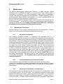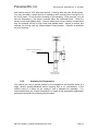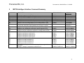
1
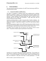
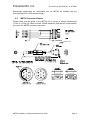
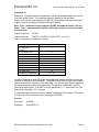
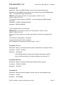
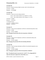
Paroscientific, Inc. MET3A Meteorological Measurement System Installation, Operation, and Maintenance Guide Document No. 8360-002 Rev. K 8/1/2002 Paroscientific, Inc. Digiquartz® Pressure Instrumentation Paroscientific, Inc. Document No. 8360-002 Rev. K. 8/1/2002 Table of Contents 1 INTRODUCTION .........................................................................................................................3 2 PERFORMANCE..........................................................................................................................3 3 BENCH VERIFICATION TEST ..................................................................................................4 3.1 REQUIRED TEST AND INSTALLATION COMPONENTS ...........................................................4 3.2 DIGIQUARTZ SOFTWARE ...............................................................................................4 3.2.1 Digiquartz CD Library ...................................................................................................4 3.2.2 Digiquartz Interactive (DQI) Software Installation .........................................................5 3.3 MET3-A BENCH TEST PROCEDURE ................................................................................6 3.4 STATUS INDICATORS ......................................................................................................6 4 FIELD INSTALLATION ..............................................................................................................7 4.1 4.2 5 COMMANDS ................................................................................................................................9 5.1 5.2 5.3 6 PHYSICAL INSTALLATION AND MOUNTING ..........................................................................7 MET3A CONNECTOR PINOUTS .......................................................................................8 MET3A COMMAND DESCRIPTIONS ..................................................................................9 ASPIRATION FAN STATUS INDICATOR ............................................................................. 14 ® DIGIQUARTZ INTELLIGENT INTERFACE COMMANDS NOT SUPPORTED BY THE MET3A......... 14 MAINTENANCE.........................................................................................................................15 6.1 MAINTENANCE PROCEDURES ........................................................................................ 15 6.1.1 Barometer Port Removal ................................................................................................15 6.1.2 Cleaning the Barometer Condensation Drain .................................................................15 6.1.3 Cleaning the Temperature / Humidity Sensor .................................................................15 6.1.4 Aspiration Fan Replacement ..........................................................................................16 7 GPS RECEIVER INTERFACE INFORMATION.....................................................................17 7.1 7.2 7.3 7.4 7.5 7.6 7.7 8 NOTES ON CALIBRATION OF MET3A SENSORS...............................................................24 8.1 8.2 8.3 8.4 8.5 8.6 9 ASHTECH Z SERIES RECEIVERS .................................................................................... 17 ASHTECH UZ CGRS RECEIVERS .................................................................................. 19 TRIMBLE NAVIGATION SERIES 4000SSE RECEIVERS ....................................................... 20 ALLEN OSBORNE TURBOROGUE RECEIVERS................................................................... 20 LEICA LB2 RECEIVERS ................................................................................................. 20 JAVAD NAVIGATION SYSTEMS (JNS) RECEIVERS (FIRMWARE 1.9 OR LATER) ...................... 20 NOVATEL RECEIVERS................................................................................................... 21 PRESSURE SENSOR ..................................................................................................... 24 PRESSURE CALIBRATION OVERVIEW .............................................................................. 24 TEMPERATURE SENSOR ............................................................................................... 24 TEMPERATURE CALIBRATION OVERVIEW ........................................................................ 24 RELATIVE HUMIDITY SENSOR ........................................................................................ 25 RELATIVE HUMIDITY CALIBRATION.................................................................................. 25 MET3A INTELLIGENT INTERFACE COMMAND SUMMARY ..........................................26 10 CUSTOMER NOTES ..............................................................................................................27 11 TECHNICAL SUPPORT ........................................................................................................28 12 ADDENDUM: ..........................................................................................................................29 MET3A Installation, Operation & Maintenance Guide Page 2 Paroscientific, Inc. 1 Document No. 8360-002 Rev. K. 8/1/2002 Introduction The Paroscientific MET3A Meteorological Measurement System is a precision instrument that measures barometric pressure, temperature, and relative humidity. The MET3A uses a tuned barometric pressure port to minimize the pressure effects of driving wind and a fan aspirated temperature / humidity port to reduce the effects of solar radiation and optimize humidity saturation recovery time. The MET3A has modest power requirements (+7 to 16VDC, @ 105mA nominal, 200mA maximum) and incorporates a bi-directional RS-232 interface for data acquisition and instrument configuration. The MET3A may be interfaced to a variety of instruments including personal computers, GPS receivers, and data loggers. The MET3A is packaged in a rugged, weatherresistant housing with a waterproof connector to provide reliable operation under adverse field conditions. Please access the Paroscientific internet site (http://www.paroscientific.com) to obtain the latest product information and application notes. 2 Performance Product is defined by Specification Control Drawing. Specifications subject to change without notice. PRESSURE (DIGIQUARTZ BAROMETRIC STANDARD) Range: 620 to 1100hPa (9 to 16 psia) Resolution: Accuracy, including pressure hysteresis, repeatability, linearity & temperature conformance: Stability: Better than 0.001 hPa Better than ±0.08 hPa Better than 0.1 hPa per year TEMPERATURE (PLATINUM RESISTANCE TEMPERATURE PROBE) Range: -50 to +60 deg C Resolution: Better than 0.01 deg C Accuracy: Better than ±0.1 deg C Stability: Better than 0.1 deg C per year RELATIVE HUMIDITY (CAPACITANCE PROBE) Range: Accuracy: Saturation recovery time: MET3A Installation, Operation & Maintenance Guide 0 to 100% Better than ±2% RH at 25 deg C 2 minutes or less Page 3 Paroscientific, Inc. 3 Document No. 8360-002 Rev. K. 8/1/2002 Bench Verification Test 3.1 Required Test And Installation Components You will need the following items to complete your bench test and field installation. 1. MET3A Meteorological Measurement System (P/N 1539-00X) Specification Drawing No. 7556-004 2. MET3A Interface Cable (P/N 2319-XXX) 3. Digiquartz CD Library (P/N 6732-201 Ver: 2.1)* 4. Power Breakout / Supply Kit* (P/N 1291-001) - 9 to 12 VDC from 110 VAC or (P/N 1291-002) - 9 to 12 VDC from 220 VAC 5. GPS Receiver Interface Adapter Cable (consult factory)* 6. PC with Windows 3.X or above.* 7. 7/16” wrench (for bracket installation) * These items may be optional for your field installation. To verify the operation of the device with a PC you will require an external power source and breakout as the PC serial port does not supply power to the MET3A. Paroscientific Power Supply Kit, part number 1291-001 or 1291-002, will simplify this process. 3.2 Digiquartz Software 3.2.1 Digiquartz CD Library The Digiquartz Library CD contains software and product literature. The Literature subdirectory contains the directories: • Adobe Acrobat • Product Data Sheet The Acrobat subdirectory includes the Adobe Acrobat Reader installation files. This program is needed to view the Product Data Sheets. The Data Sheets subdirectory contains the product literature files in Adobe PDF format. You will need an installed version of the Adobe Acrobat Reader to view/print these files. You can access these files from the menu program, which starts automatically under Windows 95/98. You must start these files from the file manager program for Windows 3.X. The Software subdirectory contains: • DigiquartzAssistant (32-bit Windows Only) • DigiquartzInteractive (16/32-bit Windows) • Samples (16 & 32 bit Windows) Utilities directories. (MS-DOS based software) MET3A Installation, Operation & Maintenance Guide Page 4 Paroscientific, Inc. Document No. 8360-002 Rev. K. 8/1/2002 The DigiquartzAssistant subdirectory includes the installation files for Digiquartz Assistant software (DQA). DQA is a 32-bit program and cannot be run under Windows 3.X. You can start the installation either from the menu program, which starts automatically under Windows 95/98, or from Explorer; go to the DigiquartzAssistant subdirectory on your CD and double click on the setup.exe program. This will start the installation. The Digiquartz Interactive subdirectory includes a readme file and the DQI1.1 subdirectory. The installation files for DigiquartzInteractive software are in the DQI1.1 subdirectory. From Windows 95 you can start the installation from the menu program or from File Explorer. From Windows 3.X you should use File Manager; go to the DQI1.1 subdirectory and double-click on setup.exe program. The Samples subdirectory includes sample code for Labview and Visual Basic programming environment to communicate with Digiquartz Intelligent Instruments. In the Labview subdirectory, there is a logger program including the installable version and some sample VIs. In the Visual Basic subdirectory, there is Visual Basic source code and an installable program which demonstrate how to communicate with Digiquartz Intelligent Instruments. The Utilities subdirectory includes some MS-DOS® utility programs ============================================================ Digiquartz is a registered trademark of Paroscientific, Inc. Acrobat Reader is a registered trademark of Adobe Inc. Windows is a registered trademark of Microsoft Corporation. ============================================================ 3.2.2 Digiquartz Interactive (DQI) Software Installation Windows 3.X: To install DQI start Windows and from the File Manager select your CD drive (generally D:). Go to the DQI1.1 subdirectory, and double-click on setup.exe. The program will check your system configuration information and will create a new program group and an icon. Windows 95/98: To install DQI start Windows and insert the CDROM. The Windows95 autoCD should run the menu program for installation of the Digiquartzsoftware. Double-click on DQI1.1 on the menu page. Alternatively, Explorer can be used to initiate the installation program. Double click on the Setup program within the main directory on the CD. MET3A Installation, Operation & Maintenance Guide Page 5 Paroscientific, Inc. 3.3 Document No. 8360-002 Rev. K. 8/1/2002 MET3-A Bench Test Procedure 1. Connect the MET3A interface cable to the power breakout and PC serial port. 2. Apply power to the unit. (+7 to 16 Vdc at 105 mA nominal, 200 mA maximum). 3. Start the DQI program. Select the Communication Port to which the MET3A is connected and press “Start”. The communication baud rate of the unit has been pre-set to 9600 baud, 8 data bits, and 1 stop bit. DQI will try to communicate with an Intelligent Instrument on the selected Communication Port by using a succession of baud rates. The screen will display a baud rate and instrument identification numbers upon successful communication. 4. Click on the OK button. 5. You should now see the DQI Configuration screen. On the top menu bar, click on “Measure” and select MET3 from the drop-down list. The MET3A measurement panel will appear on the screen. Each measurement parameter has its own window. Verify that the pressure, temperature, and humidity fields have a reasonable data value. If any field displays “------” characters, there may be a program or instrument problem. The program Help file has troubleshooting suggestions. The MET3A is shipped with a factory default configuration that is compatible with the software. Should you encounter a problem, check to be sure that the configuration parameters have not been inadvertently changed. The RS-232 interface is capable of driving signals over distances of up to 30 meters with good quality shielded cable. It is recommended that you bench test your unit with the installation cable, especially if you are driving the signal a long distance. If you are interfacing the unit to a GPS receiver, it is recommended that you verify system operation before performing the field installation. Refer to Section 6 for information on configuring and connecting the MET3A to your receiver. The DQI Configuration panel can be used to check the configuration parameters. 3.4 Status Indicators In early 2002, a status indicator panel was added to the MET3A. These status indicators allow you to determine whether input power is applied to the unit, and to monitor RS-232 serial activity. The status indicator panel is located on the bottom of the large cylindrical body of the unit, adjacent to the electrical connector. The following table explains the function of the status indicators: Indicator color Red Green Yellow Function ON: Input power on OFF: Input power off FLICKERING: Activity on RS-232 receive line OFF: No activity on RS-232 receive line FLICKERING: Activity on RS-232 transmit line OFF: No activity on RS-232 transmit line MET3A Installation, Operation & Maintenance Guide Page 6 Paroscientific, Inc. 4 Document No. 8360-002 Rev. K. 8/1/2002 Field Installation This section discusses physical installation of the MET3A and interfacing the MET3A to the data acquisition system. 4.1 Physical Installation and Mounting The MET3A is packaged to withstand adverse field conditions and no additional shielding or protection is required. We recommend that the MET3A interface cable used to connect to the recording device be protected from long-term exposure to the elements. A typical installation will include placing the cable in conduit to ensure extended cable life and reliable data transmission. Proper cable strain relief will minimize cable and connector damage. Install the mounting bracket on a pole of not more than 2 inches in diameter. (An optional flat monument mounting plate is available.) Be sure the mounting fixture and structure are capable of supporting the weight of the MET3A under adverse weather conditions. The mounting hardware supplied with the MET3A provides ground isolation from the mounting pole. No other ground connection should be made except at the recording device through the cable shield and connector shells (as shown in section 4.2). The MET3A must be installed with the barometric port assembly vertical as shown below. This position will assure optimum performance of the sensors. Barometer Pressure port Condensation Drain Port And RS-232 Connector Barometer and Electronics Enclosure Barometer Reference Height (Base of Unit) Aspirated Air Outlet Solar Shield, Housing Temperature/Humidity Sensor and Aspiration Fan Aspirated Air Inlet Install the unit in a location where the ports remain unobstructed. There should be at least one foot of clearance in all directions and at least four feet of clearance from the ground. The ports are designed to minimize effects caused by solar radiation and wind, and obstruction of the ports could result in erratic performance. For GPS MET3A Installation, Operation & Maintenance Guide Page 7 Paroscientific, Inc. Document No. 8360-002 Rev. K. 8/1/2002 Meteorology applications we recommend that the MET3A be installed with the barometer port at the GPS antenna height. 4.2 MET3A Connector Pinouts Double check that the power to the MET3A unit is correct in voltage requirements (+7Vdc to +16Vdc @ 105mA nominal, 200mA maximum) and that the communication pin-outs to the MET3A connector are correct. Earth Ground MET3A Installation, Operation & Maintenance Guide Page 8 Paroscientific, Inc. 5 Document No. 8360-002 Rev. K. 8/1/2002 Commands 5.1 MET3A Command Descriptions The MET3A intelligent interface supports a variety of commands that may be used to configure the unit and retrieve data. Refer to the Digiquartz Programming and Operations Manual, Document 8107-001, for a list of commands. With the exception of the EW command, the following commands are unique to the MET3A. These commands supplement the commands listed in the Programming and Operations Manual for other Paroscientific products. Command: EW Description: Permits the modification of a parameter value. It must be sent with any command that modifies a parameter value. Example 1: (To change a Z1 coefficient value) Command: *0100EW*0100Z1=##### Response: *0001Z1=##### Example 2: (To change a G2 coefficient value) Command: *0100EW*0100G2=##### Response: *0001G2=##### Command: P9 Description: Read unified data word containing Pressure, Temperature and Humidity measurement values based on the NMEA specification. Note: This command only functions with single devices and cannot be used in a serial loop. The instrument only responds to P9 commands when the engineering units are set to Bar (UN=3). Command: *0100P9 Typical Response: $WIXDR,P,<Pres Value>,B,<SN>,C,<Temp value>,C,<SN>,H,<Hum value>,P,<SN><CR><LF> └── Pressure ──┘ └─ Temperature ─┘ └── Humidity ──┘ Transducer Field Units Pressure P B=Bar Temperature C C=Celsius Humidity P=Percent H <SN> = Transducer Serial Number (Typically - DQ#####) MET3A Installation, Operation & Maintenance Guide Page 9 Paroscientific, Inc. Document No. 8360-002 Rev. K. 8/1/2002 Command: L1 Description: Provides pressure, temperature, and RH measurement data in a unified, fixed field length format. This format simplifies the parsing of the individual measurement values, and enhances the MET3A’s compatibility with commercial data loggers, such as the Handar 555 Data Collection Platform. Note: The L1 command is only supported by MET3A firmware revision 1.02 and above. The L1 command only functions with single devices and cannot be used in a serial loop. Typical command: *0100L1 Typical response: *098765,+00.995874,+23.45,+045.7,1<cr><lf> The L1 data record is formatted as follows: Field Start character " * " (asterisk) Serial Number field Comma Pressure field Comma Temperature field Comma RH field Comma Fan Status field Termination characters Character position (1-based) 1 2-7 8 9 – 18 19 20 – 25 26 27 – 32 33 34 35 – 36 Pressure, temperature, and RH values are padded with leading and trailing zeroes as required to maintain a fixed field width. The serial number field is padded with leading zeroes as required to maintain a fixed field width. The decimal point always appears in the same character position within each field. The pressure, temperature, and RH fields have explicit signs. If the MET3A fan is operational, a “1” is returned in the Fan Status field, otherwise a “0” is returned. To determine which firmware version is loaded, activate the VR command. VR returns the firmware version number stored in the program EPROM. Example: Command: *0100VR Response: *0001VR=01.01 MET3A Installation, Operation & Maintenance Guide Page 10 Paroscientific, Inc. Document No. 8360-002 Rev. K. 8/1/2002 Command: NH Description: Read or set NMEA header used in the P9 command response. By default, the NH (NMEA Header) string is set to produce the generic NMEA header “$WI”. The default P9 output looks like this: $WIXDR,P,<Pres Value>,B,<SN>,C,<Temp value>,C,<SN>,H,<Hum value>,P,<SN><CR><LF> To change the header string to “$PASHS,”, use the following NH (NMEA Header) command. Command: *0100EW *0100NH=$PASHS, Response: *0001NH=$PASHS, The P9 response will now look like this… $PASHS,XDR,P,<Pres Value>,B,<SN>,C,<Temp value>,C,<SN>,H,<Hum value>,P,<SN><CR><LF> Remember to add a comma to the end of the string if a comma is to appear before XDR. The maximum string length is 7 characters. Unused characters to be "null" not spaces. ASCII characters 32 through 90 are valid, except “*” and “=”. Command: TT or A1 Description: Read an external temperature sensor measurement in degrees Celsius Command: *0100TT (*0100A1) Response: *0001##.## *0001-##.## (example of response for negative temperature values). Note: See MD command for fan status indication (see section 5.3). Command: RH or A2 Description: Read an external humidity sensor measurement in percent. Command: *0100RH (*0100A2) Response: *0001##.# Command: N1 Description: Read raw analog to digital converter value for the temperature input. Command: *0100N1 Response: *0001###### MET3A Installation, Operation & Maintenance Guide Page 11 Paroscientific, Inc. Document No. 8360-002 Rev. K. 8/1/2002 Command: N2 Description: Read raw analog to digital converter value for the humidity input. Command: *0100N2 Response: *0001###### Command: AR Description: Read or set current analog resolution If AR = 0 then output resolution is 0.1 degrees C, 0.1% RH. If AR = 1 then output resolution is 0.01 degrees C, 0.1% RH. Command: *0100AR Response: *0001AR=0 To change AR value: Command: *0100EW*0100AR=1 Response: *0001AR=1 Command: Z1 Description: Read or set zero adjustment coefficient for calculated temperature value. Command: *0100Z1 Response: *0001Z1= ###### Note: Changing this parameter effects the temperature calibration! Command: Z2 Description: Read or set zero adjustment coefficient for calculated humidity value. Command: *0100Z2 Response: *0001Z2= ###### Note: Changing this parameter effects the humidity calibration! Command: M1 Description: Read or set span adjustment coefficient for calculated temperature value. Command: *0100M1 Response: *0001M1= ###### Note: Changing this parameter effects the temperature calibration! Note: The adjusted output is expressed as Ta = M1*(T + Z1); changing M1 will affect the instrument’s adjusted zero offset if M1 is not 1. MET3A Installation, Operation & Maintenance Guide Page 12 Paroscientific, Inc. Document No. 8360-002 Rev. K. 8/1/2002 Command: M2 Description: Read or set span adjustment coefficient for calculated humidity value. Command: *0100M2 Response: *0001M2= ###### Note: Changing this parameter effects the temperature calibration! Note that the adjusted output is expressed as Ha = M2*(T + Z2); changing M2 will affect the instrument’s adjusted zero offset if M2 is not 1. Command: E1, E2, F1, F2, G1, G2, H1, H2, K1, K2 Description: Read or set temperature and humidity calibration coefficients. Channel 1: E1, F1, G1, H1, K1 (temperature) Channel 2: E2, F2, G2, H2, K2 (humidity) Example: Command: *0100E1 Response: *0001E1=###### Note: Changing these parameters effect the temperature and/or humidity calibration! MET3A Installation, Operation & Maintenance Guide Page 13 Paroscientific, Inc. 5.2 Document No. 8360-002 Rev. K. 8/1/2002 Aspiration Fan Status Indicator A warning character can be added to the temperature data to indicate the operational status of the aspiration fan. This indication may be toggled on and off by using the Mode (MD) command. When the Mode is set to MD=4, a plus (+) sign will be appended to temperature measurement data if the fan is not operating properly. Example: Read or set the Mode (MD) parameter. Read the Mode setting Command: *0100MD Response: *0001MD= 04 - The mode is set to report fan status. Set the Mode setting Command: *0100EW*0100MD=4 Response: *0001MD= 04 - The mode is set to report fan status. Example: Read a temperature reading with the fan status indication. (MD=4, fan OK) Command: *0100TT Response: *000122.23 Example: Read a temperature measurement with the fan status indication. (MD=4, fan not working) Command: *0100TT Response: *000122.23+ *0001-22.23+ (example of negative temperature values). Note: The fan status indication applies to the TT, A1 and P9 commands. 5.3 Digiquartz® Intelligent Interface Commands Not Supported by the MET3A. The following commands are not supported in the MET3A. Refer to Digiquartz Programming and Operations manual for descriptions. ® Display Commands: DC, DD, DP, DR, DV Tare Commands: BP, OP, ZS, ZV, ZL 16 Bit Interface Commands: LL, LH, IM, IC MET3A Installation, Operation & Maintenance Guide Page 14 Paroscientific, Inc. 6 Document No. 8360-002 Rev. K. 8/1/2002 Maintenance The MET3A Meteorological Measurement System is a highly accurate, reliable instrument that is intended to operate for a long period of time without need of maintenance or calibration. For critical installations, yearly checks of temperature, humidity, and barometric pressure may be appropriate. Transfer standards, such as the Paroscientific Model 760-16B (for pressure), or a newly calibrated MET3A unit would be suitable for field verification of installed units. Ensuring that the MET3A package remains clean and debris-free will improve the overall performance. The electronics package is environmentally sealed, requires no cleaning or maintenance, and contains no customer serviceable parts. Opening of the sealed enclosure may affect the Paroscientific warranty. 6.1 Maintenance Procedures Periodic cleaning of the housing, barometer port inlet and temperature / humidity sensor is the only recommended physical maintenance of the unit. 6.1.1 Barometer Port Removal The cleaning procedure consists of unscrewing the barometer port in a counterclockwise direction, cleaning out any debris from between the upper and lower plates and the adjacent orifice plates and checking for unobstructed flow through the port assembly. If flow is still obstructed, the upper plate and upper orifice plate may be removed by unscrewing the ½-20UNF flat head socket screw on top of the port. Use a 5/16” Allen hex wrench. This allows access to both the orifice plates and the interior of the upper end of the column. Remove any debris from the various orifices and reassemble, applying a small amount of Loctite 609 to the screw. Torque the screw to 25 ft/lbs to secure the assembly. Prior to re-installation of the pressure port it is recommended that the Teflon pipe tape on the male ¾” thread be removed and replaced with at least three wraps of fresh tape. Carefully re-mate the barometer port to the main body of the instrument and screw the two together, HAND TIGHT. Do not over-tighten these threads. Over-tightening could cause damage to the threads and impede future dis-assembly. Do not permit water to enter the exposed port on the electronics enclosure. 6.1.2 Cleaning the Barometer Condensation Drain The condensation drain is the brass fitting with a sintered stainless steel screen, located on the underside of the upper body adjacent to the electrical connector. Inspect the screen for contamination and if necessary, clean the screen with a nylon brush and distilled water. 6.1.3 Cleaning the Temperature / Humidity Sensor You may visually check the aspirated portion of the enclosure for contamination. Prior to any cleaning activity, turn off the power. The screens are intended to prevent large particles from entering the system. Clean these with a nylon brush. It is necessary to remove the lower portion of the MET3A aspirated temperature / humidity system to access the sensor. Locate the two hex head screws found just below the upper screen MET3A Installation, Operation & Maintenance Guide Page 15 Paroscientific, Inc. Document No. 8360-002 Rev. K. 8/1/2002 and remove using a 3/32” Allen hex wrench. Carefully slide the outer housing down. You may encounter a small amount of resistance while removing this housing due to the O-ring seals. Do not force the housing off the assembly. Once removed, you will see the temperature / RH sensor mounted within the isothermal block. Clean the sensor screen with distilled water. Sensors which have become heavily contaminated may be scrubbed off with a nylon brush and distilled water. Inspect or replace and lubricate the O-rings with any silicone-based O-ring lubricant. Carefully re-assemble the outer housing. Remove and retain these two screws Remove housing, (lower vertically) 6.1.4 Aspiration Fan Replacement The internal fan used to provide airflow for the temperature and humidity probe is a highly reliable weather-hardened device requiring little or no maintenance. In the unlikely event of a failure do not replace it with a standard fan assembly. It is recommended that you contact Paroscientific to obtain all the appropriate replacement parts and instructions for performing this procedure. MET3A Installation, Operation & Maintenance Guide Page 16 Paroscientific, Inc. 7 Document No. 8360-002 Rev. K. 8/1/2002 GPS Receiver Interface Information Listed below are programming instructions which will allow you to activate your GPS receiver’s auxiliary meteorological data acquisition function. The information in this section is subject to change by the receiver manufacturer. It is recommended that you reference your receiver’s operations manual for further information. Please contact us with any additional questions about these interfaces as they change frequently. In all cases, the GPS receiver uses the P9 command to invoke a data response. The data response will be in the NMEA format. 7.1 Ashtech Z Series Receivers Interfacing the MET3A to the Ashtech Receiver A Meteorological Station can be connected to any of the four independent serial ports on the Ashtech dual-frequency GPS receivers. The Meteorological Station can even be powered by the Ashtech receiver. Please follow the directions below to interface the Paroscientific MET3A to the Ashtech Z-12. Note: The Z-12 receivers with serial numbers beginning with LPxxxx are factory configured to power up the MET3A directly through pin 16. They can be easily identified by the gray body color. Z-12 receivers with serial numbers beginning with 700xxxx do not have power on pin 16 and therefore require a power breakout kit, available from Paroscientific. See page 3, section 3.1, item 4 for a description. However, some 700 series Z-12’s (blue body color) have had a Magellan factory mod performed that supplies power to pin 16. This can only be verified by using a voltmeter. A special cable is required for proper meteorological station operation. This cable is provided by Paroscientific, part number 1499-001. This cable connects the Meteorological Station directly to the Ashtech GPS receiver. Please note that the standard download cable shipped with the Ashtech receiver (part no. 700617) will not work. Plug the interface cable into any one of the serial ports of the receiver. Push the 4 button on the front of the Ashtech Z-12 to access screen 4. Press the enter key[e] to activate the serial port menu. Press the enter [e] key to activate the cursor. Using the arrow keys, toggle the cursor to the selected serial port. Press the enter [e] key to activate the serial port menu. Using the arrow keys, toggle the cursor to the MET field. Use the + key to toggle the MET field to ON. Press the enter [e] key to confirm the MET ON status. Press the enter [e] key to activate the cursor. Using the arrow keys, toggle the cursor to the selected serial port. Using the arrow keys, toggle the cursor to the Baud Rate field. Use the + key to toggle the Baud Rate to 9600. Press the enter [e] key to confirm the Baud Rate. MET3A Installation, Operation & Maintenance Guide Page 17 Paroscientific, Inc. Document No. 8360-002 Rev. K. 8/1/2002 The Ashtech Z-12 has now been programmed to acquire MET data every five seconds. To confirm this, go to screen 9, where the MET3A temperature, pressure and humidity will be displayed. These MET data will be displayed in real-time onscreen and will also be written to the Ashtech D file every five seconds. Please consult the Ashtech CGRS manual for additional information on downloading and interpreting the D file. Note: If no data are displayed, use the Digiquartz Interactive (DQI) program supplied with the unit to change the pressure units to Bar. This is accessed using the UN command. Outputting the MET Data in Real-time In addition to storing the MET data within the Ashtech receiver, these data can also be output in real-time through any one of the remaining serial ports not in use. Please note that it is not prudent to output MET data on the same port to which the MET station is connected. The following example demonstrates how to output the MET data in real-time Turn on the receiver. Press the enter [e] key to activate the selected port menu. Press the enter [e] key to activate the port menu. Push the 4 button on the front of the Ashtech Z-12 to access screen 4. Press the enter[e] key to activate the cursor. Using the arrow keys, toggle the cursor to one of the un-used serial ports. Using the arrow keys, toggle the cursor to the Baud Rate field. Use the + key to toggle the Baud Rate field to the desired output rate. Please note that this rate can be set from 300 to 115200 baud, but rates of 9600 and higher are recommended. Press the enter [e] key to activate the cursor. Using the arrow keys, toggle the cursor to the selected port. Using the arrow keys, toggle the cursor to the NMEA field. Use the + key to toggle the NMEA field to ON. Press 1 to access the NMEA sub-menu. Using the arrow keys, toggle to the XDR field. Press the + key to toggle the XDR message to ON. Press the enter [e] key to confirm the change. The MET data will be output through the selected serial port at the chosen Baud Rate. The MET data will be contained in the NMEA (industry standard) XDR message. For additional information please consult the Ashtech CGRS manual. Ashtech offers a program called ASHTORIN, which converts the meteorological data file to a RINEX file. Please contact Ashtech Customer Support for more information: 1-800-2292400. <SN> = Transducer Serial Number (Typically - DQ#####) MET3A Installation, Operation & Maintenance Guide Page 18 Paroscientific, Inc. 7.2 Document No. 8360-002 Rev. K. 8/1/2002 Ashtech uZ CGRS Receivers Interfacing the MET3A to the uZ CGRS Receiver The uZ CGRS is designed to integrate seamlessly with a Paroscientific MET3A Meteorological Station. The MET station is attached to one of the receiver’s four serial ports. Commands are then issued to the MET Station to send its data to the receiver. MET data can then be output from the receiver as an NMEA message and/or stored in the D-File within the receiver. When using Ashtech Geodetic Base Station Software (GBSS) and the GBSS Meteorological Module, a RINEX ME file is made automatically. The following section describes how to connect the MET station to the uZ CGRS and how to verify that it is operating with the receiver. The procedure instructs you to turn off all other types of data output so that you can easily verify that the receiver is outputting MET data. Please note that once this procedure is completed, you may need to issue other commands to configure the system for your specific application. Basic MET station connection and operation verification procedure. 1. Connect the dual RS-232 I/O and MET Sensor cable (P/N 730417) to port 1 (A/C) of the powered and running uZ CGRS unit. 2. Connect the DB9 connector of cable 730417, labeled “Port A/B”, to Com 1 or 2 of your PC. 3. Connect the other DB9 connector labeled “Port C/D” to the MET cable, P/N 2319. 4. Connect the MET cable to the MET station. 5. Using communication software such as the terminal in Micro-Manager or Procomm, issue the command “$PASHQ,RAW“ to the receiver via port A. Look at the data returned and ensure EVERYTHING is listed as OFF. If everything is not off, issue command “$PASHS,OUT,PORT” to turn everything off. 6. Issue command “$PASHQ,PAR” and ensure everything for the data returned is also listed as OFF. If not, issue command “$PASHS,NME,ALL,PORT,OFF” to turn everything OFF. 7. Issue command “$PASHS,OUT,C,MET,ON” to connect the MET station via port C. 8. Issue Command “$PASHS,NME,XDR,A,ON” to enable XDR with MET information. 9. At this point the PC will display the MET station outputs about once a second. The Data received will look similar to the below string: $GPXDR,P,1.018719,B,DQ 75136,C,23.33,C,DQRHT212,H,34.7,P,DQRHT212*7C Which has the meaning: $GPXDR,P,<Pres Value>,B,<SN>,C,<Temp Value>,C,<SN>,H,<Hum Value>,P,<SN>checksum If the PC shows the “GPXDR…” string, then the MET station is on line and operating. The uZ CGRS will create a D-file with the MET data. A time tag precedes each line of data, similar to the following example. MET3A Installation, Operation & Maintenance Guide Page 19 Paroscientific, Inc. Document No. 8360-002 Rev. K. 8/1/2002 C 521092.997000,1108 XDR,P,1.008417,B,DQ 75136,C,22.88,C,DQRHT212,H,37.7,P,DQRHT212 The time tag has the format C <GPS Seconds of week>,<GPS week> The MET data has the format: XDR,P,<Pres Value>,B,<SN>,C,<Temp Value>,C,<SN>,H,<Hum Value>,P,<SN> The data between the “C”s is the temperature, in degrees Celsius, that the MET station is measuring. 7.3 Trimble Navigation Series 4000SSE Receivers The Trimble receiver should have firmware version 7.26 or later installed in order to support auxiliary meteorological devices. It is not necessary to use an initialization string with the MET3A. Use the following command substring, *0100P9 , to invoke a data response. Our auxiliary power adapter may be required depending on the age of your receiver. 7.4 Allen Osborne TurboRogue Receivers TBD 7.5 Leica LB2 Receivers It is not necessary to use an initialization string. Use the following command substring, *0100P9 , to invoke a data response. 7.6 Javad Navigation Systems (JNS) Receivers (firmware 1.9 or later) Plug the interface cable into Serial C (Port) of the receiver using an appropriate DB-9 null modem/gender changer and the standard JNS serial cable. Unless a special JNS cable is used, the user must supply power using Paroscientific’s power adapter module. (See section 3.1) Turn on the receiver. Run PC-CDU and connect to the receiver. Go to menu File and select Manual mode. Send the command: set,dev/ser/c/rate,9600 to set the baud rate of serial port C. Send the command: set,dev/ser/c/ewrap,on. Send the command: set,dev/ser/c/imode,echo. Send the command: set,dev/ser/c/echo,/cur/log. (That command assumes that you are logging to data recording memory; if logging using a PC-CDU to serial port A then send the command: set,dev/ser/c/echo,/dev/ser/a instead). MET3A Installation, Operation & Maintenance Guide Page 20 Paroscientific, Inc. Document No. 8360-002 Rev. K. 8/1/2002 Send the command: em,dev/ser/c,misc/MET3:600 to request data from the MET3 every 600 seconds (10 minutes). Other values can be specified, (the MET3 data will be collected at standardized epochs such as 00:10:00, 00:20:00, etc). Then start data logging using one of the usual methods (PCCDU or Minter). Settings are retained through power cycles so it is not necessary to send manual commands again (unless you change the device on serial port C). (Commands dm,dev/ser/c,misc/MET3 and set,dev/ser/c/echo,/dev/null can be used to turn off the data acquisition). NOTE: A temporary program which creates a RINEX MET file from a .jns file is available from [email protected]. For more information or technical support on JNS receivers, visit http://www.javad.com. 7.7 NovAtel Receivers Our MET3A is compatible with the following NovAtel receivers: • Modulated Precision Clock (MPC) receiver • OEM4 family of receivers, including: o OEM4 o Euro4 o PowerPak series o ProPak series MET3A Station Set-Up Power the MET3A station by creating the connections shown in the Figure below. Each of the connections is numbered, with each number corresponding to one of the steps provided below the figure. MET3A Installation, Operation & Maintenance Guide Page 21 Paroscientific, Inc. Document No. 8360-002 Rev. K. 8/1/2002 MET3A 1 To Receiver Power Supply To PC DE9-P Receiver –dependent connector To Antenna Power Breakout DE9-S 2 DE9-P MET3A Interface Cable DE9-S 4 Receiver Supplied by NovAtel Power Cable To Power Supply 3 Sold Separately 1. Attach the interface cable to the port located on the bottom surface of the MET3A. 2. Attach the DE9-S connector of the interface cable to the DE9-P connector of the power breakout. 3. Plug the AC adapter block at the end of the power cable into an outlet. 4. Insert the plug at the other end of the power cable into the port on the side of the breakout. Once the meteorological station is powered, verify the power LED is on. Complete the system by following the steps provided in either MPC Receiver Set-Up or OEM4 Family Receiver Set-Up depending on the receiver being used. MPC GPS Receiver Set-Up 1. Set up the MPC as described in the Quick Start section of the Modulated Precision Clock (MPC) User Manual, including supplying power to the receiver and configuring your Internet connection in order to access the Modulated Precision Clock Website. 2. Connect the DE9-S connector on the MET3A power breakout to the DGPS port MET3A Installation, Operation & Maintenance Guide Page 22 Paroscientific, Inc. Document No. 8360-002 Rev. K. 8/1/2002 on the rear panel of the MPC using the serial cable. For the location of the DGPS port, please see the section entitled Rear Panel Functionality in the Modulated Precision Clock (MPC) User Manual. 3. Set-up the software and logging functions per the Modulated Precision Clock (MPC) User Manual. OEM4 Family Receiver Set-Up To capture data using a receiver from the OEM4 family, complete the following steps per the OEM4 Family User Manual Volume 1. 1. Set up the receiver as described in the Quick Start section of the OEM4 Family User Manual Volume 1, including supplying power to the receiver and connecting an antenna. 2. Load firmware that supports meteorological data logging on to the receiver. 3. Load supplementary software on to the receiver. 4. Connect the meteorological station and the receiver. 5. Configure the receiver to log the meteorological data. To download the user manuals for either the MPC or OEM4 family of receivers, please visit the Product Manuals section NovAtel’s website at www.novatel.com/Products/productmanuals.html. For more information on NovAtel receivers, visit NovAtel’s website at www.novatel.com. MET3A Installation, Operation & Maintenance Guide Page 23 Paroscientific, Inc. 8 Document No. 8360-002 Rev. K. 8/1/2002 Notes On Calibration of MET3A Sensors 8.1 Pressure Sensor The MET3A uses a Digiquartz Barometric Standard that offers ±0.08 hPa accuracy and a 3-year stability warranty of better than 0.1 hPa per year. 8.2 Pressure Calibration Overview All Digiquartz Barometric Standard transducers are calibrated and conformance tested over their operational pressure and temperature ranges against NIST-traceable standards. Transducer output and applied pressure are recorded at test pressures that span the transducer range over a minimum of at least six different temperatures. These measurements are used to derive calibration coefficients for the best fit for each individual transducer The differences between the indicated pressures and the applied pressures from the primary standard are less than ±0.08 hPa for Digiquartz barometers. All Digiquartz barometers are stability tested for a minimum of one month after calibration. 8.3 Temperature Sensor The temperature sensor is a precision thin-film platinum 1000-ohm resistance element (RTD). The sensor was chosen for its accuracy, long-term stability, and ease of recalibration. The resolution of the sensor is better than 0.01 degree C and the accuracy is better than ±0.1 degree C over the full temperature range from –50 to + 60 degrees C. The time constant of the fully packaged sensor is approximately 15 minutes, and the self-heating of the sensor in still air is less than 0.07 degree C. The temperature probe is surrounded by a fan-aspirated solar shield, which greatly reduces the effects of direct and reflected solar radiation. 8.4 Temperature Calibration Overview The MET3A incorporates a precision thin-film RTD to sense temperature. A thermal chamber is used to control environmental temperature, and an independently calibrated, NIST traceable thermistor is used as a temperature reference. The MET3A humidity/temperature sensor is enclosed in a small isothermal block that includes a bore designed to accept a standard 0.125” diameter temperature reference probe. The bore terminates in close proximity to the humidity/temperature sensor, assuring good isothermal contact between it and the temperature reference probe. The MET3A RTD sensor and electronics are simultaneously calibrated by taking reference probe temperature and MET3A temperature measurements at various stable points over the range of –50 to +60°C, and adjusting the MET3A temperature coefficients to correct for combined temperature sensor and electronics nonlinearity. This process yields system temperature measurement accuracies of ±0.1°C or better over the temperature range of –50 to +60°C. MET3A Installation, Operation & Maintenance Guide Page 24 Paroscientific, Inc. 8.5 Document No. 8360-002 Rev. K. 8/1/2002 Relative Humidity Sensor The humidity sensor uses a polymer capacitance element. It was selected for its accuracy, stability, and resistance to contamination. Its output is corrected for temperature effects over a wide temperature range. The recovery time of the aspirated RH sensor is typically less than 2 minutes. Very large steps in humidity can take longer to reach full equilibrium. A step change of 75% RH settles within 5% of final value in 2 minutes and within 1% of final value in 5 minutes. In addition, there can be hysteresis effects of a few percent after prolonged exposure to humidity above 90% RH. 8.6 Relative Humidity Calibration The MET3A humidity sensor is a standard humidity probe characterized by the manufacturer. All MET3A units are conformance tested against a transfer standard to ensure proper performance. MET3A Installation, Operation & Maintenance Guide Page 25 Paroscientific, Inc. 9 Document No. 8360-002 Rev. K. 8/1/2002 MET3A Intelligent Interface Command Summary COMMAND DESCRIPTION INPUT COMMAND P9 L1 NH TT or A1 RH or A2 N1 N2 AR Sample and respond with NMEA formatted data values Unified Fixed Field Length Data Record Return User Defined NMEA header ($WI, - default) Sample & return external temperature measurement in deg Celsius Sample & return an external humidity measurement in percentage Sample & return an analog integer count for analog channel 1 (T) Sample & return an analog integer count for analog channel 2 (RH) Return current analog resolution; AR=0 then output resolution is 0.1 deg C, 0.1% RH; AR=1 then output resolution is 0.01 deg C, 0.1% RH Set/Return zero adjustment coefficient for analog channel 1 (T) Set/Return zero adjustment coefficient for analog channel 2 (RH) Set/Return the span adjustment coefficient for analog channel 1 (T) Set/Return the span adjustment coefficient for analog channel 2 (RH) Set/Return temperature coefficient E1 Set/Return temperature coefficient F1 Set/Return temperature coefficient G1 Set/Return temperature coefficient H1 Set/Return temperature coefficient K1 Set/Return humidity coefficient E2 Set/Return humidity coefficient F2 Set/Return humidity coefficient G2 Set/Return humidity coefficient H2 Set/Return humidity coefficient K2 Enable EPROM write for one command string. May be a global 99 command. Example: Change E1 temperature coefficient to 0.1 *0100P9 *0100L1 *0100NH *0100TT (*0100A1) *0100RH (*0100A2) *0100N1 *0100N2 *0100AR Z1 Z2 M1 M2 E1 F1 G1 H1 K1 E2 F2 G2 H2 K2 EW *0100Z1 *0100Z2 *0100M1 *0100M2 *0100E1 *0100F1 *0100G1 *0100H1 *0100K1 *0100E2 *0100F2 *0100G2 *0100H2 *0100K2 *0100EW...(cmd) OUTPUT RESPONSE $WI,XDR,…. See Section 5.1 *0001NH=$WI, *0001##.## *0001##.# *0001###### *0001###### *0001AR=0 *0001AR=1 *0001Z1=###### *0001Z2=###### *0001M1=###### *0001M2=###### *0001E1=###### *0001F1=###### *0001G1=###### *0001H1=###### *0001K1=###### *0001E2=###### *0001F2=###### *0001G2=###### *0001H2=###### *0001K2=###### Cmd Response *0100EW *0100E1=0.1 *0001E1=.1000000 26 Paroscientific, Inc. 10 Document No. 8360-002 Rev. K. 8/1/2002 Customer Notes MET3A Installation, Operation & Maintenance Guide Page 27 Paroscientific, Inc. 11 Document No. 8360-002 Rev. K. 8/1/2002 Technical Support For additional technical support please contact an application engineer at: Paroscientific, Inc. 4500 148th Ave. N.E. Redmond, WA 98052 USA Tel: (425) 883-8700 Fax: (425) 867-5407 Internet: www.paroscientific.com Email: [email protected] For further physical details of this instrument, please contact our web site. For support of interfaces between the MET3A and customer GPS systems, please access the technical support section on our web site or contact the GPS manufacturer directly. MET3A Installation, Operation & Maintenance Guide Page 28 Paroscientific, Inc. 12 Document No. 8360-002 Rev. K. 8/1/2002 ADDENDUM: MET3A units that are delivered with the barometer port dismounted from the main body should be assembled in the following manner: Apply at least three wraps of Teflon pipe tape (supplied with unit) to the ¾” male pipe thread on the top of the main body of the instrument. Ensure that the entire thread is adequately covered with the tape. Carefully mate the female thread at the base of the barometer port with the taped male thread and screw the two together HAND TIGHT. Do not overtighten these threads. Over-tightening could cause damage to the threads and impede future dis-assembly. MET3A Installation, Operation & Maintenance Guide Page 29