1
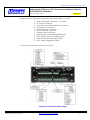
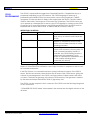
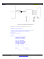
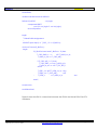
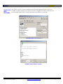
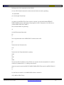
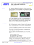
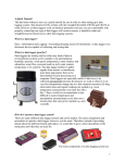
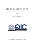
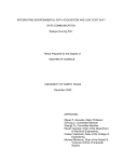
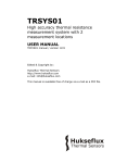
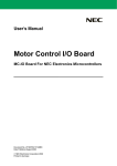
Application Note: Microcom GTX Modulator
Setting up the CR10X as an SDI-12 sensor to be Interfaced with the
MICROCOM GTX Modulator.
Author: Richard Schwarz
uAPP122 (v1.0) June 10,2005
SUMMARY
PRELIMINARY
The Microcom Model GTX Satellite Transmitter and Data Collector works on GOES, GMS, ARGOS, SCD &
METEOSAT systems. The GTX has some data logger functions built into it, including an SDI-12 and counter
input. The GTX can be programmed and can be interfaced to external data acquisition systems via its RS232 port.
Microcom GTX Satellite Transmitter
Campbell CR10X Programmable Data Logger
For example, the CR10X from Campbell Scientific is an external Data logger / Data Acquisition system
which can be interfaced to various sensors to log measurements. The CR10X has its own programming
language which allows programs to be written for various application scenarios. By connecting the CR10X
to the Microcom Design GTX Modulator, programs can be written on the CR10X can be set up as anSDIperipheral and logged measurements can then be read via the GTX SDI-12 port and then transmitted via
GOES, GMS, ARGOS, SCD and METEOSAT satellite systems.
The Campbell Scientific CR10X is a mature data logger product used in many data acquisition systems
world wide. It can interface to dozen’s of standard sensors. It also has a industry standard SDI-12 serial
interface which can easily be connected to the Microcom GTX Satellite transmitter. The programming
of the Campbell Scientific CR10X is powerful, but somewhat cryptic. This application note attempts to
cover the programming and hardware aspects of connecting the CR10X to the Microcom GTX
transmitter via the SDI-12 interface.
CAN
TB
I/O
INTRODUCTION
SERIAL
PORT
FS TRIPPED
8
FS
DATA
GPS
TX
RF
OUT
10
© 2005 Microcom Design Inc. All rights reserved voice: 401.771.1070 Fax:410.771.0018
http://www.microcomdesign.com
7
9
11
Microcom GTX Transmitter Connections
UAPP122 (v1.0) June 10, 2005
FAILSAFE
RESET
SDI 12
FS RESET
TX
RF OUT
SDI-12
GPS
+
12.5Vdc
POWER
2
6
DATA
12.5Vdc
INPUT
1
Satellite Data Transmitter
GTX - 1.0
5
4
RS-232
GPS ANT
GPS
ANT
CAN/TB
I/0
3
1
Application Note: Microcom GTX Modulator
Setting up the CR10X as an SDI-12 sensor to be Interfaced with the
MICROCOM GTX Modulator.
uAPP122 (v1.0) June 10,2005
Author: Richard Schwarz
PRELIMINARY
Provided below is a list of the major end panel components on the GTX
1.
2.
3.
4.
5.
6.
7.
8.
9.
10.
11.
Main Power Input Connector - +12.5 VDC
RF Output Connector
CAN (future) and Tipping Bucket Connector
GPS Antenna Connector
RS-232 Serial Port Connector
SDI-12 Interface Connector
Failsafe Reset Push-Button
LED4: Data in Transmit Buffer LED (Green)
LED3: GPS Receive Active LED (Green)
LED2: RF Transmit Active LED (Green)
LED1: Failsafe Tripped LED (Red)
The Campbell CR10X interface panel is shown below.
Campbell Scientific CR10X Data Logger
© 2005 Microcom Design Inc. All rights reserved voice: 401.771.1070 Fax:410.771.0018
UAPP122 (v1.0) June 10, 2005
http://www.microcomdesign.com
2
Application Note: Microcom GTX Modulator
Setting up the CR10X as an SDI-12 sensor to be Interfaced with the
MICROCOM GTX Modulator.
uAPP122 (v1.0) June 10,2005
Author: Richard Schwarz
PRELIMINARY
User’s of this application note should be familiar with, or have access to basic coding techniques, user’s
manuals and software associated with using the GTX and CR1000, including:
1)
2)
3)
Microcom GTX User’s Manual
Microcom GTX GUI Software
Campbel Scientific CR10X User’s Manual
4) Campbell Scientific LoggerNet Software
© 2005 Microcom Design Inc. All rights reserved voice: 401.771.1070 Fax:410.771.0018
UAPP122 (v1.0) June 10, 2005
http://www.microcomdesign.com
3
Setting up the CR10X as an SDI-12 sensor to be interfaced with the MICROCOM GTX-1.0 Modulator. PRELIMINARY
The CR10X is a popular Data logger from Campbell Scientific. Campbell has set up a
CR10X
PROGRAMMING proprietary interpreter for use in the device. The CR10X language is made up of
parameter based INSTRUCTIONS (routines) which can be strung together in TABLES
(programs). The device allows 3 tables to be stored inside the device. The third table is
used for subroutines. The Microcom GTX has an SDI-12 interface. The CR10X can be set
up to appear as a standard SDI-12 sensor to the GTX Transmitter. In setting up the CR10X
to respond as if it was a SDI-12 sensor, the CR10X uses INSTRUCTION 106 which must be
implemented as the first INSTUCTION in SUBROUTINE 98 (located in table 3).
INSTRUCTION 106 DETAILS:
PARAMETER
DATA TYPE
01 SDI-12 Address
4 bytes
02 TIME/VALUES
4 bytes
03 LOCATION
4 bytes
DESCRIPTION
SDI-12 address which the CR10X uses
when set up as a sensor Valid values are
(0-126)
ttnn where tt is the time in secs the CR10X
requires to complete its sensor routine,
and nn is the number (max 63) of values
(readings) returned.
The starting address location for the nn
values to be returned to the recorder. On
an M command issued by the SDI-12
controller, the CR10X Starting location =
Parameter3 (this parameter) =(n*x)
where nn is specified in Parameter2. and
x is the number following the M
command (M1,M2 etc)
Results of 106 INSTRUCTION: Will return a set of input locations in response to the M or M1M9 command sequence.
If the SDI-12 issues a V command sequence (status) indicates the status of the CRX-10
sensor. The first and second values are from the *B mode of the CR10X sensor, giving the
number of watchdog errors in the CR10X, and the number of table overruns that have
occurred. The third is a signature of the sensor CR10X memory. The signature is created
by the same technique that INSTRUCTION 19 (signature) uses.
The CR10X can also respond to the I command. The CR10X send the following string back
to the I command:
“10CAMPBEL CR10X 001 aaaa” where aaaa is the number from the eighth window of the
*B mode.
© 2005 Microcom Design Inc. All rights reserved voice: 401.771.1070 Fax:410.771.0018
UAPP122 (v1.0) June 10, 2005
http://www.microcomdesign.com
4
Setting up the CR10X as an SDI-12 sensor to be interfaced with the MICROCOM GTX-1.0 Modulator. PRELIMINARY
The CR10X has a D9 port on it which can be used for programming the CR10X. The D9 is
CONNECTING
NOT A STANDARD SERIAL PINOUT. Rather it has the following pinout:
UP THE CR10X
PROGRAMMING PIN #
USE
Input or Output Description
PORT TO A
1
5V
OUTPUT
5VDC output
LAPTOP SERIAL
2
GND
Ground
3
RING
INPUT
Raised high by peripheral to put the CR10X in
PORT
4
5
RXD
ME
INPUT
OUTPUT
6
SDE
OUTPUT
7
CLK/
Handshake
NC
TXD
INPUT/
OUTPUT
8
9
OUTPUT
the telecommunications mode (TTL levels)
Receive data (TTL levels)
Modem Enable signal raised by CR10X in
response to the RING signal (TTL Levels)
Synchronous Device Enable (not used in SDI12 mode)
Not used in SDI-12 mode
Transmit data (TTL levels)
Since TTL levels are being used we need to use a translator like the MAX 3223 RS232
transceiver chip. Besides the TX and RX data transceiver pair , an additional data
transceiver pair is needed for the ME and RING line. The RING and ME lines will be
connected to the RTS and CTS lines on a standard RS232 port on our laptop. This allows us
to control the RING line and monitor the ME line.
For our testing we will use the APS-V240 FPGA board to handle the interface between
the GTX and the CR10X. The APS-V240 has an on board MAX3323 chip with an on board
D9 connector (J11) and an FPGA. The V240 board runs the connections through an
FPGA which also allows for line switching inverting and for various test patterns to be
transmitted if needed. A D9 was connected between the V240 FPGA pins and the
CR10X to both control and change the levels of the RS232 lines of the Laptop PC into the
required levels of the CR10X. The FPGA design could later be used to do any other
simulations or prototyping or testing for the CR10X D9 control port. Figure 1 shows the
connections between the PC LAPTOP and the APS-V240 and the CR10X. LEDs on the
APS-V240 are also connected to the RING/ME/RX data lines for monitoring purposes. An
optical cable is available from Campbell which does the job of level translation and pin
swapping.
© 2005 Microcom Design Inc. All rights reserved voice: 401.771.1070 Fax:410.771.0018
UAPP122 (v1.0) June 10, 2005
http://www.microcomdesign.com
5
Setting up the CR10X as an SDI-12 sensor to be interfaced with the MICROCOM GTX-1.0 Modulator. PRELIMINARY
Figure 1 CR10X Programming port connections
The VHDL code for the V240 on board FPGA is shown below:
use IEEE.STD_LOGIC_UNSIGNED.ALL;
-- Uncomment the following lines to use the declarations that are
-- provided for instantiating Xilinx primitive components.
--library UNISIM;
--use UNISIM.VComponents.all;
entity rs232ttl is
Port (
T_rs232_rx_in : in std_logic;
T_rs232_tx_out : out std_logic;
T_rs232_cts_in : in std_logic;
T_rs232_rts_out : out std_logic;
T_Osc_I : in STD_LOGIC;
T_CSIO_RING_o: out std_logic;
T_CSIO_RXD_o: out std_logic;
T_CSIO_ME_i: in std_logic;
-T_CSIO_SDE_i: in std_logic;
-T_CSIO_CLK_HS_io: inout std_logic;
T_CS_TXD_i: in std_logic;
T_LED1_o
:
T_LED2_o
:
-T_LED3_o
out STD_LOGIC;
out STD_LOGIC
:
out STD_LOGIC
);
© 2005 Microcom Design Inc. All rights reserved voice: 401.771.1070 Fax:410.771.0018
UAPP122 (v1.0) June 10, 2005
http://www.microcomdesign.com
6
Setting up the CR10X as an SDI-12 sensor to be interfaced with the MICROCOM GTX-1.0 Modulator. PRELIMINARY
end rs232ttl;
architecture Behavioral of rs232ttl is
SIGNAL S_BufOSC
: std_logic;
component IBUFG
port (I: in std_logic O: out std_logic);
end component;
begin
--- Global Buffer Assignments
-U3: IBUFG port map (I => T_OSC_i, O => S_BufOsc);
clockout: Process(S_BufOsc) -begin
if (S_BufOsc'event and S_BufOsc = '0') then
T_CSIO_RING_o <=
NOT T_rs232_cts_in;
T_rs232_rts_out <= T_CSIO_ME_i;
if (T_CSIO_ME_i = '1') then
T_CSIO_RXD_o <= not T_rs232_rx_in;
T_rs232_tx_out <= NOT T_CS_TXD_i;
end if;
--
T_LED1_o <= NOT T_rs232_cts_in; --ring
T_LED2_o <= T_CSIO_ME_i;
--me
T_LED3_o
<= T_rs232_rx_in;
--rxd
end if;
end process;
end Behavioral;
Figure 2 shows the SDI-12 connections between the CR10X and the MICROCOM GTX
modulator
© 2005 Microcom Design Inc. All rights reserved voice: 401.771.1070 Fax:410.771.0018
UAPP122 (v1.0) June 10, 2005
http://www.microcomdesign.com
7
Setting up the CR10X as an SDI-12 sensor to be interfaced with the MICROCOM GTX-1.0 Modulator. PRELIMINARY
Figure 2 SDI-12 connections
© 2005 Microcom Design Inc. All rights reserved voice: 401.771.1070 Fax:410.771.0018
UAPP122 (v1.0) June 10, 2005
http://www.microcomdesign.com
8
Setting up the CR10X as an SDI-12 sensor to be interfaced with the MICROCOM GTX-1.0 Modulator. PRELIMINARY
CR10X/GTX The CR10X has user software available which aid in programming the CR10X. The
PC200W software will be used in terminal mode to program the CR10X, while the GTX
USER
Software will be used in SDI-12 terminal mode to send SDI-12 commands.
SOFTWARE
PC200W CR10X Setup Screen
PC200W Control Software Screens
© 2005 Microcom Design Inc. All rights reserved voice: 401.771.1070 Fax:410.771.0018
UAPP122 (v1.0) June 10, 2005
http://www.microcomdesign.com
9
Setting up the CR10X as an SDI-12 sensor to be interfaced with the MICROCOM GTX-1.0 Modulator. PRELIMINARY
MICROCOM GTX SOFTWARE SCREENS
© 2005 Microcom Design Inc. All rights reserved voice: 401.771.1070 Fax:410.771.0018
UAPP122 (v1.0) June 10, 2005
http://www.microcomdesign.com
10
Setting up the CR10X as an SDI-12 sensor to be interfaced with the MICROCOM GTX-1.0 Modulator. PRELIMINARY
Setting up the 106 command on the CR10X:
On the CR10X terminal enter the telecommunications mode by pressing:
7H and ENTER
you should get this prompt
>
In order to use INSTRUCTION 106 we have to place it in the dedicated INTERRUPT
SUBROUTINE 98 (which will interrupt the program on SDI-12 requests). We will have to
create SUBROUTINE 98 in TABLE 3
First we enter table 3 by pressing
*3
At the P00 prompt then press
85
A
The only parameter is the SUBROUTINE number which is 98
98
A
Then enter the 106 Instruction
106
A
Then enter the 106 parameters by typing:
0009
A
0001
A
0000
This sets the SDI-12 address of the CR10X to 9 and sets the time required to 0, and the
number of parameters to 1, starting at location 0.
then we need to enter the END OF SUBROUTINE INSTRUCTION which is INSTRUCTION 95.
95
A
So the Pseudo code for our SUBROUTINE written in table 3 is:
I-85 (LABEL INSTRUCTION)
© 2005 Microcom Design Inc. All rights reserved voice: 401.771.1070 Fax:410.771.0018
UAPP122 (v1.0) June 10, 2005
http://www.microcomdesign.com
11
Setting up the CR10X as an SDI-12 sensor to be interfaced with the MICROCOM GTX-1.0 Modulator. PRELIMINARY
P1 – 98 (parameter one is the SUBROUTINE #)
I-106 (“SET CR10X as SDI-12 SENSOR” INSTRUCTION)
P1- 0009 (parameter 1 – SDI-12 address)
P2- 0001 (parameter 2- zero time / 1 measurement)
P3- 0000 (parameter 3- starting location 0000)
I-95 (“END OF SUBROUTINE” INSTRUCTION)
Now one additional thing: The 106 INSTRUCTON requires 182 intermediate locations
which means we have to change the default number of intermediate locations
available. We do this by using the *A command (mode A).
*A
and then changing the second parameter to a larger number then 182 ..lets try 200.
Now here is what the terminal IO looked like:
*7H
// this puts us in telecom mode
>
// hit * here and it changes the > prompt to MODE
MODE 03:0000 //hit 3 to go into 3 mode (subroutine table)
01:P85
// enter first instruction 85
01:98
// only parameter is the subroutine number which is 98
02:P00 106
// enter the next instruction which is the 106 (set to SDI-12 sensor)
01:0000 0009 // enter first parameter
02:0000 0001 // enter second parameter
03:0000 0000 // enter third parameter
03:P00 95
// enter the END of SUBROUTINE instruction (95)
04:P00 // hit * and get MODE prompt
MODE 10 // enter A mode
01:0028 //just hit enter (don’t change parameter 1)
02:0064 200 // change parameter 2 (intermediate locations) to 200
//hit * to get MODE prompt
MODE 00 //type in 0 to compile program
LOG
*0
So we now have set the CR10X up as an SDI-12 sensor with an SDI-12 address of 9.
To test this we will use the Microcom SDI-12 terminal to send an I command an see if
the CR10X responds correctly.
In the terminal we send the aI! command where a = SDI-12 address or in our case a 9.
© 2005 Microcom Design Inc. All rights reserved voice: 401.771.1070 Fax:410.771.0018
UAPP122 (v1.0) June 10, 2005
http://www.microcomdesign.com
12
Setting up the CR10X as an SDI-12 sensor to be interfaced with the MICROCOM GTX-1.0 Modulator. PRELIMINARY
The figure below shows the response of the CR10X to the command being sent.
Then we send the 9V! command which will get the status of the CRX10 as shown
© 2005 Microcom Design Inc. All rights reserved voice: 401.771.1070 Fax:410.771.0018
UAPP122 (v1.0) June 10, 2005
http://www.microcomdesign.com
13
Setting up the CR10X as an SDI-12 sensor to be interfaced with the MICROCOM GTX-1.0 Modulator. PRELIMINARY
Now to set up a real programming example of taking a measurement (we’ll use the
internal CR10X internal temperature) every 5 seconds and store it in location 1. We will
then try and read the measurement from the CR10X from the SDI-12 terminal of the
GTX software.
We have to take the measurement using in TABLE 1. So:
*1
>
MODE 01:0000 //enter mode 1
SCAN RATE +0.0000 5 //set timing to every 5 seconds
01:P00 17 // enter INSTRUCTION 17 (take internal temp)
01:0000 1 // parameter one stores the temp in location 1
02:P00 // compile the program
MODE 00
now lets change the 106 instruction to read from location 1 instead of 0.
© 2005 Microcom Design Inc. All rights reserved voice: 401.771.1070 Fax:410.771.0018
UAPP122 (v1.0) June 10, 2005
http://www.microcomdesign.com
14
Setting up the CR10X as an SDI-12 sensor to be interfaced with the MICROCOM GTX-1.0 Modulator. PRELIMINARY
7H
>
MODE 03:0000
01:P85
01:98
02:P106
01:0009
02:0001
03:0000 1
//change to location 1
03:P95
04:P00
MODE 00
LOG 1
*
If Loggernet software is available, then the following EDLOG code does essentially the
same thing:
© 2005 Microcom Design Inc. All rights reserved voice: 401.771.1070 Fax:410.771.0018
UAPP122 (v1.0) June 10, 2005
http://www.microcomdesign.com
15
Setting up the CR10X as an SDI-12 sensor to be interfaced with the MICROCOM GTX-1.0 Modulator. PRELIMINARY
GTX SDI-12 COMMAND TESTING
Now we need to send an M (measure) command from the SDI-12 terminal on the GTX.
We send the 9!M command
Ok now lets store the programs off into flash
enter the SAVE/Load Mode:
*D
then the store command
6
A
then the program name (number) to save
1
© 2005 Microcom Design Inc. All rights reserved voice: 401.771.1070 Fax:410.771.0018
UAPP122 (v1.0) June 10, 2005
http://www.microcomdesign.com
16
Setting up the CR10X as an SDI-12 sensor to be interfaced with the MICROCOM GTX-1.0 Modulator. PRELIMINARY
A
then repeat the process
*D
6
A
98
A
//store subroutine 98
Now the device holds both the main program (1) and the interrupt subprogram (98).
To recall the programs:
*D
7
A
98
A
*D
7
A
1
A
Now that the terminal program works and shows that the data has come into the GTX,
we can set up a program on the GTX. Opening the GTX GUI configuration file called
cr10X_SDI12_ex1.txt . In this configuration you can see that SENSORS are enabled on
the transmission screen, and that the SDI-12 parameter is read from address 9.
© 2005 Microcom Design Inc. All rights reserved voice: 401.771.1070 Fax:410.771.0018
UAPP122 (v1.0) June 10, 2005
http://www.microcomdesign.com
17
Setting up the CR10X as an SDI-12 sensor to be interfaced with the MICROCOM GTX-1.0 Modulator. PRELIMINARY
© 2005 Microcom Design Inc. All rights reserved voice: 401.771.1070 Fax:410.771.0018
UAPP122 (v1.0) June 10, 2005
http://www.microcomdesign.com
18
Setting up the CR10X as an SDI-12 sensor to be interfaced with the MICROCOM GTX-1.0 Modulator. PRELIMINARY
Interface Cables
Using the APS-V240 board as we did earlier is not practical for field use.
Several options exist to replace this interface APS-V240 interface card.
A programming interface cable for the CR10x (to a PC) is available from
Campbell (either the SC32B or the SC929).
A Microcom B40 Interface Cable which has a MAX232 chip embedded in the
D9 Shroud could also be used
In order to make the cable attach to the DTE (pinned male) PC serial port, a
DCE port should be used (female). (NO MODIFICATIONS TO PIN 2 AND 3)
should be done to the B40 interface cable.
On the other end of the cable the TX and RX data should be a dual CMOS
© 2005 Microcom Design Inc. All rights reserved voice: 401.771.1070 Fax:410.771.0018
UAPP122 (v1.0) June 10, 2005
http://www.microcomdesign.com
19
Setting up the CR10X as an SDI-12 sensor to be interfaced with the MICROCOM GTX-1.0 Modulator. PRELIMINARY
inverter (ie a NL27WZU04 from ON Semiconductor) should invert the data from
the CR10x and to the CR10x.
Such that:
PC<-> DCE D9—MAX232---------cable---------------NL27WZU04—DTE D9 <-> CR10X
MAX232CWE pin 11 attaches to green wire which connects to pin 6 of
NL27WZU04 (CR10X).
MAX232CWE pin 12 attaches to the white wire which connects to pin 3 of the
NL27W..
Pin 1 of NL27 attached to Pin 9 of the DTE D9 at the other end of the cable to
be attached to the CR10X programming port
Pin 4 of the DTE D9 CR10X end of the cable gets connected to pin 4 of
NL27W..
NL27W pin 2 connects to Pin 2 of D9 DTE connector (GND)
NL27W pin 1 connects to Pin 1 of D9 DTE connector (VCC)
short out DTE D9 pin 1 to DTE D9 pin 3 (RING)
This cable should allow the PC to program the CR10X.
A custom cable from Microcom Design may be available which incorporates
the changes to the Microcom B40 cable, and makes it a standard product.
Check with Microcom Design for the availability of this cable.
Conclusion
Revision
History
The MICROCOM Model GTX Satellite Transmitter and Data collector has
internal SDI-12 data logger capability. The CR10X from Campbell Scientific is a
data logger which can interface to other sensors and then connect to the
Microcom GTX Satellite Transmitter via the GTX’s SDI-12 serial interface. Sensor
data from the CR10X can then be sent to the GTX making the CR10X appear
as a sensor to the GTX, who can then transmit the data over a satellite. This
application note covered the connections and programming of the CR10X
and GTX.
Date
Version
Revision
June 10, 2005
1.0
Initial Microcom Preliminary Release
© 2005 Microcom Design Inc. All rights reserved voice: 401.771.1070 Fax:410.771.0018
UAPP122 (v1.0) June 10, 2005
http://www.microcomdesign.com
20