1
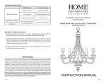
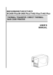
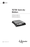
USER MANUAL
SUMMARY
Tipping Device
p2
Remote Control
p4
Motorised Rollers
p6
Ramp and Board
p8
Charge and Battery
p 10
Electric Circuit Diagram
p 12
KLAVIER-ROLLER®
353 rue des Marais
F- 74410 SAINT-JORIOZ
+33 450 68 99 40
+33 668 36 03 89
www.klavier-roller.com
1
TIPPING DEVICE
Important:
The different elements of the tipping equipment are made of plywood with inserted
iron nuts. Do not over-tighten the screws. Doing so is not only unnecessary, it
can also damage the equipment. Snug but moderate tightening is sufficient.
- view demonstration video before first use
- if piano has carrying bars screwed to side, remove them
- if piano has wing nuts protruding under keyboard, replace with flat-headed screws
PUTTING THE PIANO ON EDGE
1) remove pedal lyre
2) attach keyboard box to keyboard
- adjust slide to fit and tighten knobbed screws
- tighten keyboard box clamps with knobbed screws (without over-tightening)
3) hang shoe on piano lid by placing the shoe’s two rubber-coated clasps on top
of the lid, so that the shoe hangs down the side of the piano
4) position the front of the shoe so that the tongue of the keyboard box* fits into
the appropriate groove in the shoe
5) attach shoe :
- screw to keyboard box with BTR type hexagonal screws (remove from holding
holes inside of shoe)
- attach clamp (tighten hard)
- tighten piano lid strap
- secure safety block (can be placed after tipping the piano)
6) attach rear wheel
- place tire in direction of tipping and in contact with piano case
- place rubber tongue in downwards position
- securely tighten screws
7) attach tipping device
- maintain tipping device in vertical position, tighten screws moderately
8) to tip piano on edge:
- lift pivoting leg of tipping device by pulling on left handle
- remove left leg of piano
- position carpet under tipping device
- fold pivoting leg by pulling on right handle of tipping device
- control tipping movement with keyboard box handle (on underside of box)
- remove tipping device and piano legs
2
PUTTING PIANO UPRIGHT
1) put rear wheel and right leg of piano in position
2) attach rear wheel
- wheel underneath
- rubber tongue towards piano leg castor
3) attach tipping device (tighten screws moderately)
4) to swing piano upright :
- pull piano towards you with keyboard box handle
- leave piano on tipping device and move to other side
- lift pivoting leg of tipping device by pulling on left handle
- put left leg of piano in position and place carpet underneath
- fold in pivoting leg of tipping device by pulling on right handle
- piano has weight on its leg
5) remove tipping device
6) move piano off of carpet
7) remove shoe : clamp, screws in keyboard box, strap
8) remove keyboard box and rear wheel
9) attach pedal lyre
* the grooves in the front of the shoe are for positioning the piano so that it is properly
balanced on the rollers.
- size 280 shoe: 4 grooves, the one furthest forward for a full-sized piano, the next one
for a 3/4 size, the third one for a 1/2 size and the last for a 1/4 size.
- size 230 shoe: 3 grooves, the one furthest forward for a 3/4 size piano, the middle one
for a 1/2 size and the last one for a 1/4 size.
- size 210 shoe: 2 grooves, the one furthest forward for a 1/2 size piano, the other one
for a 1/4 size.
3
USING REMOTE CONTROL DEVICE
1
2
3
4
5
6
7
Indicator lights:
tail end lifting
propulsion
keyboard lifting
central wheels
A
B
KLAVIER-ROLLER
4
The A and B buttons select the motor to be used. These buttons have 2 positions.
The motor selected is shown by the red indicator lights.
The buttons 1 to 6 control the operation of the selected motors.
2 and 5 control both rollers in unison, 1 and 4 control the left roller only, 3 and 6
the right roller only.
The red 7 button is used for descending only.
OPERATION
To lift tail end of piano (select motor with button A)
2 => lifts piano at tail end by raising lifting bar – stops automatically when piano
is fully lifted and lifting bar is blocked in rollers
5 => lowers piano at tail end by lowering lifting bar - stops automatically at end
of travel
To lift keyboard end of piano (select motor with button A)
2 => lifts piano at keyboard end
5 => lowers piano at keyboard end
Central wheels (select motor with button B)
2 => raises rollers by lowering central wheels – stops automatically when rollers
reach end of travel
5 => lowers rollers by raising central wheels – stops automatically when rollers
are on all 6 wheels
1 => raises left roller by lowering left central wheel
3 => raises right roller by lowering right central wheel
4 => lowers left roller by raising left central wheel
6 => lowers right roller by raising right central wheel
Motorised propulsion (select motor with button B)
2 => forward (keyboard in front)
5 => backward
3 => left turn going forwards*
1 => right turn going forwards*
4 => right turn going backwards*
6 => left turn going backwards*
* raise rollers onto (lowered) central wheels before turning
7 (red button) => motorised propulsion at reduced speed for descending slopes
- No motor is selected by default when remote control device is first connected
- A beeping sound is emitted while motors are in operation
- The motors for the lifting bar and the central wheels stop automatically at end of travel
- After a few minutes without use the remote control device goes into security mode: the
indicator lights blink and the remote control no longer works. Disconnect and reconnect
remote control to reactivate. The remote control can be connected to any one of the 4
available sockets (2 on each roller). Disconnect remote control when not in use.
5
MOTORISED ROLLERS
Important notice:
The rollers constitute a lifting and light transportation device that must be used
with caution.
The instructions written in bold face type must be strictly followed.
Improper use of the rollers can result in damage to the equipment.
LOADING THE PIANO
1) position the rollers correctly on either side of the piano (keyboard stickers on
rollers towards piano keyboard, protective carpet against edge of piano)
2) pass the iron lifting bars in the rungs under the shoe at the arrow marks
3) first plug in the connecting wire between the rollers and only afterwards the
remote control wire
4) first lift piano at the tail end, keeping the rollers straight
5) then lift at the keyboard end (as indicated by the arrows on the rollers)
6) activate the rear lever again to lock the lifting bar
7) remove small stabilizing wheels
8) lift rollers a few centimetres onto the central wheels for manoeuvring
UNLOADING THE PIANO
1) be sure that rollers are on all 6 wheels (raise central wheels)
2) put small lateral stabilising wheels on rollers
3) first lower lifting bars on keyboard end (according to arrows on rollers) =>
Caution: if a beeping sound is heard, this means that the rollers are raised on
the lowered central wheels: stop unloading and lower rollers by lifting central
wheels
4) lower lifting bar on tail end of piano
5) remove lifting bars and unplug wires
6) use steel shafts for manoeuvring rollers
MOTORISED PROPULSION
- on level ground, lift rollers several centimetres onto central wheels in order to
turn or push equipment (without using motors)
- before any slope, even slight, stop and engage motors using roller handles
=> do not force motor engagement handles
in case of blocking, activate propulsion motor until easy engagement occurs
6
TURNING
the rollers turn only when balanced on central wheels
=> NEVER ATTEMPT TO TURN WHEN ROLLERS ARE ON ALL 6 WHEELS :
lift rollers onto central wheels before turning
CLIMBING A STAIRCASE
- do not turn at the start of a climb when the central wheels are in the air
- drive rollers from the side or above (do not stay underneath the equipment)
- on a long staircase, lift rollers slightly onto central wheels in order to correct
trajectory (the rollers do not climb in a perfectly straight line due to unequal
weight of piano on each roller)
- lower rollers onto all 6 wheels before arriving at top of staircase
- hold roller handles when at staircase landing
DESCENDING
- put rollers on all 6 wheels (lift central wheels)
- use red button to begin descending
- always descend tail end first, keyboard end above
- at the beginning of the descent, hold roller firmly by the handle to keep it in a
straight line and down the slope when the sled rubs against the edge of the
staircase (or on the top of the aluminium ramp)
FOR TRANSPORTING IN THE VAN
- check that rollers are on all 6 wheels (lift central wheels)
- with the motors, bring rollers into contact with a stopping block at the front of
the van, and leave motors engaged
- attach transporting stirrup with straps
- unplug remote control device
MANOEUVRING EMPTY ROLLERS
- load empty shoe or assemble the 2 rollers against each other with the 36 cm
short lifting bars
MAINTENANCE OF ROLLERS
- inflate tires regularly (recommended pressure: 4 bars)
- lubricate lifting screws if necessary => use Loctite 8103 GR135 only
central wheel lowering can be interrupted if the central wheel lifting screws are
not sufficiently greased.
7
ALUMINIUM RAMP AND PLYWOOD BOARDS
Aluminium ramp and
plywood boards
A short staircase, …
… a bit longer, …
… even longer.
second plywood board
short extensions
half-round supporting block
first plywood board
the aluminium
ramp does not
touch the floor
the boards must overlap
upper contact plate
rubber-coated
supports
For very long staircases, remove lower board when freed,
place it above, and so on...
Using plywood board
8
ALUMINIUM RAMP
- maximum vertical clearing height:
1.30 m (4’3”) with 2 metre (6’7”) ramp
1.90 m (6’3”) with 3 metre (9’10”) ramp
- maximum authorised weight: 750 kg (1650 lbs.)
- ramp should have weight resting on either end (do not lay down on a staircase)
- adjust upper contact angle with appropriate knobs according to angle of slope
- in case of slippery ground lay a wooden board flat at end of ramp
- the aluminium ramp can be used at the start of a staircase
WOODEN BOARDS FOR USE ON STAIRCASES
- lay wooden boards on staircase and ensure stability
- boards must overlap
- use extensions for filling in spaces of a few steps
- at top of stairway, screw half-round supporting block onto underside of board
and place on last step (to keep board from breaking or scraping)
- top of board should not be higher than staircase landing
- Note: the boards bend when roller wheels are on them and particularly over the
spaces between stairs. This suppleness provides better adherence to stair
edges and provides greater overall safety.
STAIRWELL LANDINGS
- to be able to turn at 90 or 180 degrees when on a landing, the depth and width
of the landing must be at least equal to the length of the rollers. For example, a
KR210 cannot turn completely on a landing with less than 210 centimetres
(6’11") on a side
- in the case of a stairway with a flat and straight intermediary landing whose
length is shorter than that of the rollers: place the aluminium ramp on the landing
so the rollers’ central wheels touch the ground before starting on the second part
of the stairway
9
BATTERIES AND BATTERY CHARGING
Meaning of indicator lights on roller covers:
ROLLERS IN USE
The remote control device and connecting wire are plugged in
- meaning of “volt” indicator lights when motors are stopped:
- green light = batteries are fully charged
- yellow light = batteries are discharging
- red light = batteries are weak
- the 3 red "ampere" lights are off
- the single red light in the middle is blinking
- when motors are in use, the yellow or red lights are on according to electrical
current
CHARGING ROLLERS
To recharge rollers, disconnect remote control device, connect charging wire to
each roller and the “cigarette lighter” socket in the battery charger
- the 3 red "ampere" lights go on
- the 3 red lights go off one by one as batteries charge up
- when only one red light is on still, charge is almost full
- when only the single green light is on, charging is finished and the battery charger cuts off automatically
- new batteries can require long charging times
- charging time varies between 1 and 6 hours depending on battery condition
and state of discharge
- the green "volt" indicator light is on during charging, or the yellow light goes on
if batteries are very weak
- the red indicator light in the middle is off
- if necessary, batteries can be charged by plugging into the vehicle’s cigarette
lighter socket (with engine running)
Note: it is not possible to fully charge batteries using the cigarette lighter socket,
which will only charge heavily discharged batteries
=> charge batteries using Klavier-Roller provided charger only.
An improper charger can damage the electric circuits
10
red
•
• • •
•
•
•
•
volt
red
red
red
green
green
yellow
red
current indicator lights on rollers covers
BATTERIES
Model: YUASA NP17-12 (12V 17Ah)
Valve-Regulated Gas Recombination Sealed Lead-Acid Battery
BATTERY LIFE (at 20°C):
100% depth of discharge: 180 cycles
50% depth of discharge: 540 cycles
30% depth of discharge: 1200 cycles
Recharge batteries after each use to increase battery lifespan
Self Discharge (at 20°C)
1 month
3%
3 months
9%
6 months
15%
How to recognise old batteries:
- batteries charge and discharge quickly
- motors are slower
- caution! Completely dead batteries do not work at all
=> REMOVE FUSES BEFORE CHANGING BATTERIES
11
ELECTRICAL CIRCUIT DIAGRAM
Electrical malfunctions can require intervention on the electric control circuit
boards.
=> Contact a Klavier-Roller technician before any intervention.
The diagram opposite can help the Klavier-Roller technician guide you for troubleshooting.
IMPORTANT: before any intervention on the circuit board, remove 25A
fuses to avoid risk of short-circuiting.
To access the circuit board:
- disconnect connecting wire and remote control device
- remove the two screws on roller cover
- remove cover
- reconnect remote control device for testing
- the LED lights are visible for diagnosing the problem
To remove the circuit board:
- remove 25A battery fuses
- disconnect battery connectors
- pull circuit board upwards
- disconnect all wires and connectors in order to remove it
(to change a relay, for example)
To reinstall the circuit board:
- connect the 2 multiple terminals and then the single connectors according to
the colour codes
Notice
• only accidental short-circuits may blow the 3A or 10A fuses, standard automotive fuses
• if the 3A fuse blows, nothing will work. If the 10A fuse blows, only the battery
charging doesn't work
• all relays, except N°1 and N°9, are heavy duty and must be replaced by 30A
relays.
The original N°1 and N°9 relays may replace any other relay and may be replaced by any standard 10A automotive relay
12
battery charge / relay 9
power on / relay 1
battery 1 (-)
battery 2 (-)
battery 2 (+)
battery 1 (+)
relay 7
relay 8
propelling / relay 10
central wheel / relay 3
These LED lights are
connected in parallel to
the corresponding
relays coils and light up
when a relay is on.
front lifting / relay 2
IMPORTANT:
remove battery fuses
(25A) before any
interventions, thus
avoiding any short circuits
rear lifting / relay 4
RELAY BOARD OUTLAYING
24 volts on / relays 5 & 6
RELAY BOARD OUTLAYING
1
central wheel motor
front lifting motor
rear lifting motor
5
6
24 volts switching on
Fuses
common
connection
for the 3
motors
3A
board
powering
2
This shorting strap
makes it possible
to increase the lifting
motors' power:
standard
front lifting
motor
10A
3
7
8
up- or
forwards
down- or
backwards
9
10
central wheel
motor
4
battery
charging
propelling
motor
increased
battery charger (-)
}
propulsion
motors
battery charger (+)
rear lifting
motor
This shorting strap
selects the actuated roller:
right hand roller (D)
left hand roller (G)
Press here
D
G
To remove these connectors,
press fastening clip on their
lower side to unlock.
13