1
User’s
Manual
54011
TM20 Thermo-Collector
IM 54011-E
3rd Edition: Jan. 2007
This instruction manual describes how to operate the TM20 Termo-Collector.
■ Intended readers
This manual is addressed to those who actually measure temperatures with a TM20 ThermoCollector and those who set up a TM20 Thermo-Collector and perform data processing with
a TM20 Thermo-Collector, i.e., operators and engineers.
■ Structure of this manual
This manual is composed of four parts:
● Before Use
Be sure to read this part before using the TM20. This part explains fundamentals such as the
name and functions of each part of the TM20 and how to input characters.
● Preparing for Measurement
Read this part before measuring a temperature. This part explains the Thermo-Collector
software and how to set up your TM20.
● Measuring Temperatures
Read this part when measuring temperatures. This part explains major operations required to
actually measure temperatures.
● Working with Measured Data
Read this part when using and analyzing the data measured by a TM20. This part explains
how to transfer the measured data to a personal computer and print them.
■ Checking contents of package
When a TM20 Thermo-Collector is delivered, visually check it to ensure that it is not damaged. Also make sure that the following items have been supplied. If any of the items are
missing, please contact the dealer from which you purchased the TM20.
Keep this box in case this product needs to be returned to the manufacturer for repair.
Item name
Quantity
TM20 Thermo-Collector
1
Floppy disks of Thermo-Collector software installer
3
ANSI AA (IEC LR6) alkaline batteries
2
Dust-proof seals (for sealing screw holes at the rear of TM20 Thermo-Collector)
2
Instruction Manual (this document)
1
Waterproof cover
1
IM 54011-E
i
■ Safety precautions
● About this manual
• Read this manual to gain a thorough understanding of this product before use.
• This manual only describes the functions of the product and makes no warranty of any
kind, including but not limited to, implied warranties of merchantability and suitability for
a particular purpose.
• All rights reserved. No part of this manual may be reproduced in any form without Yokogawa
Meters & Instruments Corporation’s written permission.
• The contents of this manual are subject to change without notice.
• Should the user find any errors, or unclear or missing information in this manual, contact
the dealer from which you purchased the product or the Marketing Department of Yokogawa
Meters & Instruments.
● Disassembly or modification
• DO NOT disassemble or modify the product. Only service personnel qualified by Yokogawa
M&C are allowed to disassemble and service the product.
● Handling precautions
• Only parts and consumables specified by Yokogawa Meters & Instruments should be used
in the product.
• Do not store the product in a location where it will be exposed to direct sunlight or high
temperatures, otherwise it may be discolored or deformed.
● Warnings, cautions, and notes
• Follow the safety instructions in this manual when handling a TM20 or its connected accessories. Yokogawa Meters & Instruments assume no liability for safety if conduct contradicts the safety instructions.
WARNING mark at the rear of the TM20 indicates the precautions that must be
• The
observed when handling the TM20. Refer to this manual for handling of the TM20.
• Throughout this manual, the following safety conventions are used:
Warning
Indicates hazard where a risk of severe injury and loss of life of the user exists.
Caution
Indicates hazard where a risk of injury of the user or damage to the product or other
equipment exists.
Note
Draws attention to important information about handling of the product or helpful information about the operations and functions of the product.
ii
IM 54011-E
TIP
Provides a tip or information supplementary to the main text.
See Also
Provides one or more references to related topics in this document.
■ Precautions for handling of components
Be sure to observe the following precautions to avoid injury and loss of life of personnel, and
damage to the equipment used.
● Probe
Warning
Do not point the tip of the needle themo probe at a person. It is very sharp and may
cause injury.
Caution
• Do not touch the stylus (metal part) of a probe that has just been used to measure a
high temperature as it may cause a burn.
• Make sure that the potential differences between probes do not exceed 1 V.
• Do not use a worn or damaged probe, which may be incapable of correct temperature measurements.
• Before removing a probe from the TM20, pull the probe away from the object measured.
• When using a probe for liquids, such as a needle probe, insert it into the liquid to be
measured by approximately half the dimension of the probe’s stylus (metal part).
Inserting it too deeply may cause a burn due to heat transfer to the probe grip as
well as cause damage to the probe itself.
• The probe grip and the cable connected from the TM20 must be maintained at a
temperature between –20°C and 50°C. Unlike the stylus of a probe, these parts have
a low resistance to heat.
• When sending data in real-time, use an ungrounded probe.
IM 54011-E
iii
● Batteries
Caution
• Be sure to remove the batteries if the product will not be used for a long period.
Otherwise, the battery liquid may leak and damage the circuitry, resulting in a malfunction.
• Whenever replacing batteries, be sure to replace both batteries with new ones. Changing only one battery may result in the charge current from the new battery flowing to
the old one.
■ Disclaimer of guarantee
• Yokogawa M&C Corporation does not guarantee this product in any way, except as set
forth in the terms and conditions of the certificate.
• Yokogawa M&C Corporation shall not be liable for any consequent or inconsequent damages to the customer or a third party arising from the use of the product due to any defect in
materials or workmanship beyond the control of Yokogawa Meters & Instruments Corporation.
■ Figures in this manual
For ease of understanding, figures and illustrations in this manual may not precisely depict
the actual product or software.
■ Care of product
• If there is a need to clean the casing, wipe the surfaces with a wrung wet cloth.
• To remove tough stains, use a cloth dampened with a diluted neutral detergent. Do not use
any solvent, other detergent, or chemical other than neutral detergents to prevent the product from being damaged.
• Keep the connectors and other conductive parts dry to prevent the product from being
damaged.
• When using the product in a place where water may splash the product, use the waterproof
case that comes with the product to prevent the product from becoming dirty and enhance
the product’s water resistance.
■ Maintenance service
When the product needs to be serviced or repaired, contact the dealer from which you purchased the product.
◆ Trademarks
• Microsoft, Windows, Windows 95, Windows 98, Windows NT, and Excel are trademarks
or registered trademarks of Microsoft Corporation, United States.
• Other company and product names appearing in this document are trademarks or registered
trademarks of the respective holders.
iv
IM 54011-E
CONTENTS
■
■
■
■
■
■
■
■
■
Intended readers ....................................................................................................................... i
Structure of this manual ........................................................................................................... i
Checking contents of package ................................................................................................. i
Safety precautions ................................................................................................................... ii
Precautions for handling of components ................................................................................ iii
Disclaimer of guarantee ......................................................................................................... iv
Figures in this manual ............................................................................................................ iv
Care of product ...................................................................................................................... iv
Maintenance service ............................................................................................................... iv
Before Use
1 Features of This Product .................................................................. 1
■
■
Collector function ................................................................................................................... 1
Logging function ..................................................................................................................... 2
2 Names and Functions of Each Part .................................................. 3
3 Setting the Battery ............................................................................ 4
4 Turn ON/OFF of the Power Supply ................................................... 5
■
■
Turn the power supply to ON ................................................................................................. 5
Turn the power supply to OFF ................................................................................................ 5
5 Screen (LCD) Displays ..................................................................... 6
6 How to Input Characters ................................................................... 7
■
■
Entering characters .................................................................................................................. 7
Entering lowercase characters ................................................................................................. 7
Preparing for Measurement
1 Overview of Preparation for Measurement ....................................... 8
2 Setting Up the Main Unit ................................................................... 9
2.1
Setting the date and time ........................................................................................ 9
2.2
Setting the name of the main unit .......................................................................... 10
3 Setting Up with the Personal Computer.......................................... 11
3.1
Setting up the “Thermo-Collector” software ........................................................... 11
■
■
■
■
3.2
11
12
14
15
Basic operation of Thermo-Collector software ...................................................... 16
■
■
■
■
IM 54011-E
Connecting the personal computer and the main unit ...........................................................
Installing the “Thermo-Collector” software .........................................................................
Confirming the communication environment (on the personal computer) ...........................
Confirming the communication environment (on the main unit) .........................................
Initiating Thermo-Collector software ...................................................................................
Terminating Thermo-Collector software ..............................................................................
Saving the setup data in a file ...............................................................................................
Loading a file containing the setup data ...............................................................................
16
17
17
18
v
■
■
■
■
Saving the measurement operator name data ........................................................................
Loading the measurement operator name file .......................................................................
Other functions (Menu functions) .........................................................................................
Other functions (Tool icons functions) .................................................................................
19
20
21
25
3.3
Files created on a computer for settings of TM20 ................................................. 26
3.4
Setups required to use collector function (setting tag names, alarms, name of
person, and comment, and selecting input channel(s)) ......................................... 27
■
■
■
■
3.5
27
29
35
37
Setups required to use the logging function (setting the log name, input channel,
measurement interval, and measurement period) ................................................. 39
■
■
3.6
Setup contents .......................................................................................................................
Setting tags ............................................................................................................................
Setting operator names ..........................................................................................................
Setting comments ..................................................................................................................
Setup contents ....................................................................................................................... 39
Setting logs ............................................................................................................................ 40
Downloading the setup data to the main unit ........................................................ 42
■
■
■
■
Preparation for downloading .................................................................................................
Downloading the tag and log setup data to the personal computer ......................................
Downloading the measurement operator name data .............................................................
Downloading comment settings ............................................................................................
42
43
44
45
4 Setting Up with the Main Unit ......................................................... 46
4.1
Setups required to use collector function (setting tag names, alarms, name of
person, and comment, and selecting input channel(s)) ......................................... 46
■
■
■
■
■
■
4.2
Setup contents .......................................................................................................................
Creating a new tag ................................................................................................................
Setting the alarm function for each tag .................................................................................
Batch-setting the alarm function ...........................................................................................
Registering the measurement operator name ........................................................................
Setting comments ..................................................................................................................
46
46
47
49
50
51
Setups required to use the logging function (setting the log name, input channel,
measurement interval, and measurement period) ................................................. 52
■
■
Setup contents ....................................................................................................................... 52
Operation procedure .............................................................................................................. 53
5 Confirm, Modify, Clear, or Delete the Data with the Main Unit ....... 55
vi
5.1
Confirming the number of pieces of tag data ........................................................ 55
5.2
Modifying the tag name ......................................................................................... 55
5.3
Clearing the measurement data associated with the tag ...................................... 56
5.4
Deleting the tag ..................................................................................................... 57
5.5
Confirming the log setup data ............................................................................... 58
5.6
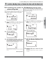
Modifying the log name and setup data (measurement interval and period) ........ 58
5.7
Clearing the measurement data associated with the log ....................................... 61
5.8
Deleting the log ..................................................................................................... 61
5.9
Batch-clearing the measurement data associated with both the tag and log ........ 62
IM 54011-E
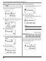
5.10 Initializing the main unit ......................................................................................... 63
5.11 Confirming the current operator name .................................................................. 63
5.12 Modifying the operator ........................................................................................... 64
Measuring Temperatures
1
2
3
4
Input Channel and Probe................................................................ 65
Measuring Temperatures with the Collector Function..................... 67
Measuring Temperatures with the Logging Function ...................... 69
Measuring Temperatures of Channels A and B Simultaneously ..... 71
■
■
■
Plugging in probes ................................................................................................................ 71
Selecting input channels ....................................................................................................... 71
Recording measured values .................................................................................................. 72
5 Measuring Temperatures with the Non-Contact Thermo Probe ..... 73
■
■
Switching on/off the decimal portion of the temperature display ......................................... 73
Measuring with the non-contact thermo probe ..................................................................... 74
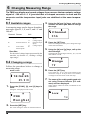
6 Changing Measuring Range ........................................................... 76
6.1
Available ranges .................................................................................................... 76
6.2
Changing a range .................................................................................................. 76
6.3
Scaling a voltage input range ................................................................................ 78
■
■
What scaling is ...................................................................................................................... 78
Setting procedure .................................................................................................................. 78
7 Other Useful Functions ................................................................... 80
■
■
■
■
■
■
■
■
■
■
■
■
■
■
■
■
■
IM 54011-E
To instantly confrm or clear the measured data on the main unit ......................................... 80
To start a measurement in the logging mode at a specified time (timer function) ................ 80
To quickly search for a tag or log ......................................................................................... 82
To record measured data if the tag or log has not been set ................................................... 82
To record the start time and finish time of an operation (only with the collector function) . 83
To restrict inputs from the panel keys (the key lock function) ............................................. 83
To enable only the panel keys (yellow keys) requied for mesurement (FUNC lock function) .... 84
To automatically turn off the power supply if no operation is performed in a specified period of
time (Auto Power Off function) ............................................................................................ 84
To determine how much more data can be recorded ............................................................ 84
To see the number of measured data pieces recorded on the tag or log ................................ 84
To see the average of the measured data ............................................................................... 85
To sound a chime at the specified time (the chime function) ............................................... 85
To view the screen in a dark place (the backlight function) ................................................. 85
To turn off the electronically generated sound ...................................................................... 85
To view the comments set ..................................................................................................... 85
To correct measured temperatures (using the simplified input correction function) ............ 86
To transmit measured values to a PC in real-time ................................................................ 87
vii
Working with Measured Data
1 Receiving the Data on the Personal Computer .............................. 88
■
■
Preparation before reception ................................................................................................. 88
Receiving the data ................................................................................................................. 89
2 Outputting Directly from the Main Unit to the Printer ...................... 91
2.1
Output preparation ................................................................................................. 91
■
■
2.2
Printer-main unit connection ................................................................................................. 91
Confirming the printer setup conditions ............................................................................... 92
Outputting the measured data to the printer .......................................................... 93
APPENDIX
■
■
■
■
■
viii
Thermo-collector specifications ............................................................................................ 96
Operation environment of Thermo-Collector software ........................................................ 99
External view and dimensions .............................................................................................. 99
Using the waterproof case (Model 93011 coming with TM20) .......................................... 100
Function keys quick reference ............................................................................................ 101
IM 54011-E
1 Features of This Product
1
Features of This Product
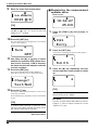
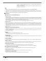
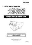
■ Collector function
The collector function is used when the measured temperature and measurement conditions
are recorded under the specified “tag”.
In the “tag”, the tag name (i.e. “what”), date and time (i.e. “when”), operator name (i.e. “who”),
and alarm (i.e. “judgment on the measured data”) are recorded as the measurement conditions, in addition to the measured temperature.
Tag name ("what")
[Line A ]
HiAlarm=0080.0 LoAlarm=0060.0
Measurement temperature
No.
Date
00001
00002
00003
00004
00005
00006
00007
00008
00009
00010
99/10/08/18:00:00
99/10/08/18:00:10
99/10/08/18:00:25
99/10/08/18:00:35
99/10/08/18:00:45
99/10/08/19:00:00
99/10/08/19:00:11
99/10/08/19:00:26
99/10/08/19:00:34
99/10/08/19:00:47
Data
Hi
Lo
Person
56.0°C
57.5°C
58.5°C
59.8°C
61.2°C
62.0°C
62.0°C
70.0°C
75.0°C
81.0°C
OK
OK
OK
OK
OK
OK
OK
OK
OK
NG
NG
NG
NG
NG
OK
OK
OK
OK
OK
OK
Smith
Smith
Smith
Smith
Smith
Smith
Smith
Smith
Smith
Smith
Operator name ("who")
Date and time ("when")
Alarm
("measured data judgment")
NG = No Good
Printout of image from a recommended printer
It is possible to use maximum 50 tags, and in these 50 tags, a total of 5,000 pieces of temperature measurement data can be recorded. However, the more the data is saved with the logging
function, the less number of measurements can be made with the collector function.
[TIP]
At the two-channel simultaneous measurement, 2 data can be recorded in every measurement. If no
data is recorded at the two-channel simultaneous measurement, 2,500 measurements can be recorded.
Set up the following tag items in advance to use the collector function.
• Tag name
• Input channel
• Alarm
• Operator name
See Also
For more information, refer to the “Preparing for Measurement” part.
IM 54011-E
1
Before Use
This product is a handy-type thermometer that can measure a temperature and
make a record of it. It has a “collector function” to record the measured temperatures and measurement conditions under the specified tag, and a “logging function” to automatically measure and record temperatures at given intervals.
The TM20 can simultaneously measure temperatures of channels A and B as well
as being able to measure a potential difference. The following describes the collector and logging functions.
1 Features of This Product
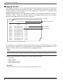
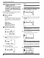
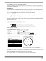
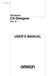
■ Logging function
The logging function is used to automatically measure temperatures at given measurement
intervals and to continue to record the result data. This function is useful when a temperature
variation within a certain period of time (e.g. temperature variation in a refrigerator being
transported) needs to be recorded.
With this logging function, the temperatures and date (year/month/day) and time will be recorded as a “log”. Unlike the collector function, the logging function does not record the
operator name and alarm (measured data judgment).
Log name
[Line B ]
Measurement interval
Interval=00:00:10
No.
Date
00001
00002
00003
00004
00005
00006
00007
00008
00009
00010
99/10/09/20:00:00
99/10/09/20:00:10
99/10/09/20:00:20
99/10/09/20:00:30
99/10/09/20:00:40
99/10/09/20:00:50
99/10/09/20:01:00
99/10/09/20:01:10
99/10/09/20:01:20
99/10/09/20:01:30
Data
-10.5°C
-10.5°C
-11.0°C
-10.5°C
-10.5°C
-11.0°C
-10.5°C
-10.5°C
-11.0°C
-10.5°C
Temperature
Date and time
Printout of image from a recommended printer
It is possible to use maximum 10 logs, and in these 10 logs, a total of 20,000 pieces of data
can be recorded. However, the more the data is saved with the collector function, the less
number of measurements can be made with the logging function.
[TIP]
At the two-channel simultaneous measurement, 2 data can be recorded in every measurement. If no
data is recorded at the two-channel simultaneous measurement, 10,000 measurements can be recorded.
Set up the following items in advance to use the logging function.
• Log name
• Input channel
• Measurement interval
• Measurement period
See Also
For more information, refer to the “Preparing for Measurement” part.
2
IM 54011-E
2 Names and Functions of Each Part
2
Names and Functions of Each Part
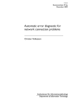
Top face
Front face
Back face
Before Use
Measuring
temperature ranges
[4]
[1]
[15]
[7]
[8]
[5]
[6]
Bottom face
MEMORY
CH
ESC
LOGGING
POWER
FUNC
SET
CLEAR
ABC
DEF
GHI
JKL
MNO
PQRS
YUV
WXYZ
[9]
[10]
[11]
[12]
[13]
[2]
WARNING
Made in
Japan
D
RS232C
NO.
[16]
Yokogawa M&C Corporation
xymbol
[3]
[14]
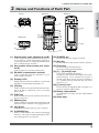
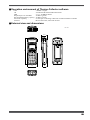
[1] External probe jacks (channels A and B)
Used to plug in the cables of thermocouple type K, J,
E, or T probes or voltage measurement (±100 mV or
±1 mV range) sensors. (A voltage measurement probe
has a U-shaped omega connector.)
[2] Non-contact thermo probe jack (channel D)
Used to connect a non-contact thermo probe.
[3] RS-232C communication terminal
Used to output data from this instrument to a personal computer or printer.
[4] Display (LCD)
Displays Thermo-Collector conditions, various setup
information, measurement temperature, etc.
[5] [CH] key
Used to switch over the input channel between channels A, B, and D. Channel D is for a non-contact
thermo probe.
[6] [ESC] key
Used to cancel the previous operation and return to
the previous screen.
[10] [POWER] key
Used to turn the power supply on and off.
[11] [Set] key
Used to make the setup contents valid for operation.
[12] [Func] key
Used to set up the selected function.
Also used to delete the measured data.
[13] [1],...,[9], and [0] keys
Used to enter alphabets and numbers.
The [0] key is also used for switching the unit of temperature display. If, for example, this [0] key is
pressed in the Home screen, the unit is switched to
“⬚F”. Another pressing of the same key will restore
the unit to “⬚C”.
[14] [<] and [>] keys
Used to retrieve the logged tag data or log data, or to
select the character input position.
[15] Battery compartment
Accommodates two ANSI AA (IEC LR6) alkaline
batteries.
[16] Name plate
[7] [Memory] key
Used to commence a temperature measurement with
either the collector function or the logging function.
[8] [▼] [▲] key
Used to select an appropriate tag, log, or function.
[9] [LOGGING] key
Used to switch between the collector and logging
functions. Also used to modify alphanumeric characters from uppercase to lowercase.
IM 54011-E
3
3 Setting the Battery
3
Setting the Battery
Two ANSI AA (IEC LR6) alkaline batteries are included with this instrument.
1.
Open the battery compartment cover at the back of the main unit.
See Also
For the position of the battery compartment, refer to Chapter 2, “Names and Functions of Each Part”.
2.
Observing the correct polarity, install the two ANSI AA (IEC LR6) alkaline batteries in
the battery compartment.
Caution
Observe the correct polarity when installing the batteries in the battery compartment.
The main unit may be damaged if the batteries are installed incorrectly.
3.
Close the battery compartment cover.
-End of procedure-
Caution
Remove old batteries from the compartment. Battery liquid leakage may cause the
main unit to malfunction or may damage it. A “BatteryEmpty” message will appear on
the LCD shortly before the battery life expires. When this message appears, replace
the batteries.
Note
• Whenever replacing batteries, be sure to replace both batteries with new ones. Changing only one
battery may result in the charge current from the new battery flowing to the old one.
• If temperature suddenly change, condensation may occur. Set the batteries after acclimatizing the
batteries and TM20 to the ambient temperature.
4
IM 54011-E
4 Turn ON/OFF of the Power Supply
4
Turn ON/OFF of the Power Supply
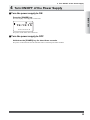
■ Turn the power supply to ON
Before Use
Press the [POWER] key.
The time display screen appears on the LCD.
19:13:15
––––––––
The power of the main unit is turned on.
■ Turn the power supply to OFF
Hold down the [POWER] key for about three seconds.
The power to the main unit will be shut down after a short beep has been sounded.
IM 54011-E
5
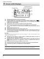
5 Screen (LCD) Displays
5
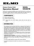
Screen (LCD) Displays
[5]
[6]
[7]
[8]
[1]
[2]
[9]
[10]
[3]
[4]
12:30:00
0 0 2 8 .5⬚C
[11]
[12]
[1]
Indicates that the chime function is being set.
[2]
Indicates whether the current mode is the collector mode or logging mode. If LOG is
displayed, the current mode is the logging mode. If it is not displayed, the current
mode is the collector mode.
[3]
[4]
Indicates the input channels currently used for measurement.
Indicates that the measurement data is being logged into the instrument.
The “ ” mark indicates the status that the “Real-time data transmission” can be
used.
Indicates that the alarm is set.
Indicates that either the [<] or [>] key can be used.
Indicates that either the key lock or FUNC lock is set. If the key lock function is
on, all the keys are disabled. In the FUNC lock state, only the temperature measurement keys can be used.
[5]
[6]
[7]
See Also
For information about canceling the lock state, refer to Chapter 7, “Other Useful Functions” in the
“Measuring Temperatures” part.
[8]
Indicates that the battery is almost used up. Replace the battery as soon as
possible after this symbol is displayed.
[9] Indicates that the instrument is set so that the power to the main unit will be
automatically turned off if no operation is made in a predetermined period of
time.
[10] Indicates that either the [▲] or [▼] key can be used.
[11] Indicates that the timer function is on and the instrument is in the wait state.
[12] A tag name, log name, and temperature will be displayed.
[TIP]
If this instrument is used in a location where the ambient temperature is low, the characters may be
displayed slowly. Note that this does not indicate the main unit being at a malfunction.
6
IM 54011-E
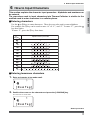
6 How to Input Characters
6
How to Input Characters
■ Entering characters
Use the 0 to ➈ keys to enter characters. These keys are also used to enter alphabets.
For example, the ➁ key can be used to enter “A” to “C”, and “2”. To enter “C”, press the
key three times.
To enter “2”, press the ➁ key four times.
Mode
Alphanumeric input mode
Key
1
1
2
ABC
3
DEF
4
GHI
5
JKL
6
MNO
7
B
C
2
E
F
3
G
H
I
4
J
K
L
5
M
N
O
6
Q
T
TUV
9
W
WXYZ
Symbol
A
D
P
PQRS
8
0
2
0
!
#
$
R
U
X
%
S
V
8
Y
&
7
Z
(
9
)
+
-
=
■ Entering lowercase characters
1.
Enter a character to be made small.
A
[NewTag]
2.
Position the cursor on the character and press the [LOGGING] key.
This character is made small.
a
[NewTag]
- End of procedure
IM 54011-E
7
Before Use
This section explains the character input procedure. Alphabets and numbers can
be entered.
The procedure used to input characters into Thermo-Collector is similar to the
method used to enter characters in a cellular phone.
1 Overview of Preparation for Measurement
1
Overview of Preparation for Measurement
Before measuring temperatures, set the tag names, etc., on the main unit.
There are two methods for making the settings. One is for the main unit and the
other is for a personal computer. For efficiency, use a personal computer to set
many items.
Setting up the main unit
• Setting the date and time
• Setting the name of the main unit
Setting up TM20 from PC
Setting up TM20 via TM20’s faceplate
Make settings (using a tag/log table) for:
• Collector function
such as the tag names, input
channel(s) used, alarms, name
of the operator, and comments.
• Logging function
such as the log name, input
channel(s) used, measurement
interval, and measurement
period.
Make settings for:
• Collector function
such as the tag names, input
channel(s) used, alarms, name
of the operator, and comments.
• Logging function
such as the log name, input
channel(s) used, measurement
interval, and measurement
period.
Download:
• Settings.
• Name of the operator.
Measure the temperature
: Setup to be performed in this part
8
IM 54011-E
2 Setting Up the Main Unit
2
Setting Up the Main Unit
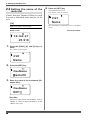
2.1 Setting the date and time
4.
Press the [SET] key.
A screen for setting the time appears.
Home screen
Time
18:54:27
22225.9°C
[TIP]
1.
Press the [FUNC], [6], and [1] keys, in
order.
The “ClockSet” screen appears on the LCD.
5.
Enter the time.
6.
Press the [SET] key.
The specified time is set.
Preparing for
Measurement
This screen which displays the current time is
referred to as the “Home” screen. All the functions in the main unit are accessed from this
screen.
18:56:14
F61
ClockSet
Press the [ESC] key repeatedly to return to the Home
screen.
-End of procedure-
F61
ClockSet
2.
Press the [SET] key.
A screen for setting the date appears.
Date
98/11/11
3.
Enter the date.
Use the [0] to [9] keys for input. The [<] or [>] key
moves the cursor.
IM 54011-E
9
2 Setting Up the Main Unit
2.2 Setting
the name of the
main unit
If more than one Thermo-Collector is used
at a time, a individual name must be set for
each.
[TIP]
Make this setting as necessary.
Home screen
4.
Press the [SET] key.
The instrument name is set.
The “Name” screen is restored.
F97
Name
Press the [ESC] key repeatedly to return to the Home
screen.
-End of procedure-
18:54:27
22225.9°C
1.
Press the [FUNC], [9], and [7] keys, in
order.
The “Name” screen appears.
F97
Name
2.
Press the [SET] key.
DevName
Name00--3.
Enter the name of the instrument (Example: NO1).
DevNamee
NO1
See Also
For how to enter letters and numbers, refer to
Chapter 6, “How to Input Characters” in the
“Before Use” part.
10
IM 54011-E
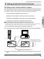
3 Setting Up with the Personal Computer
3
Setting Up with the Personal Computer
3.1 Setting up the “Thermo-Collector” software
The setup operation required for the main unit can be performed on a personal computer.
The “Thermo-Collector” software must be used to do this. This section explains the procedure used to set up the “Thermo-Collector” software on the personal computer.
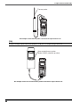
■ Connecting the personal computer and the main unit
Purchase an RS-232C cable (Model name: 910 09, round DIN 8-pin to D-sub 25-pin type).
Follow the procedure below to connect the main unit to the personal computer.
1.
Turn off the power to both the personal computer and main unit.
2.
Connect the personal computer and the main unit as shown in the following diagram.
MEMORY
CH
ESC
LOGGING
POWER
FUNC
SET
CLEAR
ABC
DEF
GHI
JKL
MNO
PQRS
YUV
WXYZ
Symbol
Main unit
Personal computer
Dedicated cable (Model name: 910 09)
D
Bottom of the
main unit (8-pin)
Serial port of the personal
computer (with 25-pin connector)
Connection between connector pins
(Round DIN 8-pin to D-sub 25-pin)
1
4
2
2
3
5
4
3
7
7
8
7
5, 6 (N.C.)
Plug this cable into the connector so that the
“ ” mark on the grip faces downward.
3.
First turn on the power to the main unit, then turn on the power to the personal computer.
-End of procedure-
IM 54011-E
11
Preparing for
Measurement
Connecting the personal computer and the main unit
↓
Installing the “Thermo-Collector” software on the personal computer
↓
Confirming the communication environment (on the personal computer)
↓
Confirming the communication environment (on the main unit)
3 Setting Up with the Personal Computer
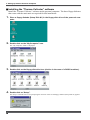
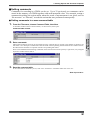
■ Installing the “Thermo-Collector” software
Install the “Thermo-Collector” software on the personal computer. The three floppy diskettes
that come with the main unit are required for this installation.
1.
Place a floppy diskette (Setup Disk #1) in the floppy disk drive of the personal computer.
2.
Double-click on the “My Computer” icon.
The “My Computer” folder is displayed.
3.
Double-click on the floppy disk drive icon (A:drive in the case of a DOS/V machine).
4.
Double-click on “Setup”.
The Setup is initiated and a screen prompting the insertion of the second floppy diskette (Setup Disk #2) appears.
12
IM 54011-E
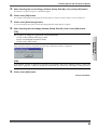
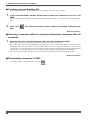
3 Setting Up with the Personal Computer
5.
After inserting the second floppy diskette (Setup Disk #2), click on the [OK] button.
Precautions to be observed prior to installation appears.
6.
Click on the [OK] button.
The installer of the application program is initiated and the “Thermo Collector Setup” screen is displayed.
7.
Click on the [Start Setup] button.
A screen prompting the insertion of the third floppy diskette (Setup Disk #3) appears.
8.
After inserting the third floppy diskette (Setup Disk #3), click on the [OK] button.
[TIP]
Preparing for
Measurement
Do as follows to change the application install destination.
1.Click on the [Change Directory] button.
2.Select a installation destination folder.
3.Click on the [OK] button.
After installation has been completed, the following confirmation window is displayed.
[TIP]
If the another window is displayed, set the new group name and click [Continue] button. (Select the
name from “group list” when you already have the name you want to use, and click [Continue] button.
9.
Click on the [OK] button.
-End of procedure-
IM 54011-E
13
3 Setting Up with the Personal Computer
■ Confirming the communication environment (on the personal computer)
Confirm the settings related to the communication environment on the personal computer.
1.
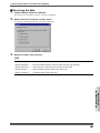
2.
Select “Thermo-Collector” in the “Programs” accessed from the “Start” menu.
Select “Properties” from the “Comm” menu.
The “Properties” window is displayed.
3.
Confirm that the settings are exactly as shown in the above figure.
If any of the settings are different, set them to the values given below.
Setup item
Setting value
CommPort
Baud Rate
Parity
Data Bits
Stop Bits
1
9600
None
8
2
[TIP]
The communication port setting values vary, depending on the type of personal computer. For more
information, refer to the manual supplied with your personal computer.
-End of procedure-
14
IM 54011-E
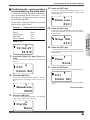
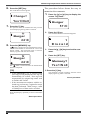
3 Setting Up with the Personal Computer
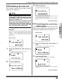
■ Confirming the communication
environment (on the main unit)
4.
A screen for setting the data length appears. Confirm that the displayed data length is as shown in the
following figure.
Confirm the settings related to communication environment on the main unit. Confirm that the settings are exactly as shown
in the following table.
If any of the settings are different, set them
to the values given below.
Setup item
Setting value (Factory Settings)
Baud Rate
Parity
Data Length
Stop Bits
9600
Data Len
8bit
5.
Press the [SET] key.
A screen for setting the number of stop bits appears.
The displayed number of stop bits is 2 bits, which is
factory setting.
Stop Bit
Home screen
2bit
18:54:27
6.
A screen for setting the flow control method appears.
The displayed flow control method is None, which is
factory setting.
22225.9°C
1.
Press the [FUNC], [5], and [1] keys, in
order.
Flow
A screen for setting the communication environment
appears.
None
7.
F51
Press the [SET] key.
Press the [SET] key.
Returns to the communication environment setup screen.
Comm Set
2.
Press the [SET] key.
F51
A screen for setting the baud rate appears. The displayed baud rate is 9600 bps, which is factory setting.
Comm Set
Press the [ESC] key repeatedly to return to the Home
screen.
Baudrate
-End of procedure-
9600
3.
Press the [SET] key.
A screen for setting the parity appears. The displayed
parity is None, which is factory setting.
Parity
None
IM 54011-E
15
Preparing for
Measurement
None
8bit
2bit
None
Flow Control
Press the [SET] key.
3 Setting Up with the Personal Computer
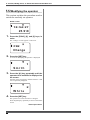
3.2 Basic operation of Thermo-Collector software
This section explains the basic operation of the supplied software.
■ Initiating Thermo-Collector software
1.
Select “Thermo-Collector” in the “Programs” accessed from the “Start” menu.
At first, the model (of the Thermo-Collector) selection screen is displayed.
2.
Click the text-box to select the model TM20.
3.
Click on the [OK] button.
After the main screen of the software is displayed, the “Setup Tags/Logs - New” screen is displayed.
16
IM 54011-E
3 Setting Up with the Personal Computer
■ Terminating Thermo-Collector software
Preparing for
Measurement
Select “Exit” from the “File” menu.
■ Saving the setup data in a file
1.
Select “Save As” in the “Setup Tags/Logs” menu accessed from the “File” menu.
The “Save As” window is displayed.
2.
Enter a file name in the “File name” field, then click on the [Save] button.
The setup data is saved.
-End of procedure-
IM 54011-E
17
3 Setting Up with the Personal Computer
■ Loading a file containing the setup data
1.
Select “Open” in the “Setup Tags/Logs” menu accessed from the “File” menu.
The “Open” window is displayed.
2.
Select a file to be loaded, then click on the [Open] button.
The specified file containing the setup data is loaded, and the tag and log setup data in the file is displayed.
-End of procedure-
18
IM 54011-E
3 Setting Up with the Personal Computer
■ Saving the measurement operator name data
The operator data is saved in a file different from that in which the tag and log data is stored.
1.
Select “Save As” in the “Setup Persons” menu accessed from the “File” menu.
The “Save as” window is displayed.
Preparing for
Measurement
2.
Enter a file name in the “File name” field, then click on the [Save] button.
The measurement operator name data being set is saved.
-End of procedure-
IM 54011-E
19
3 Setting Up with the Personal Computer
■ Loading the measurement operator name file
1.
Select “Open” in the “Setup Persons” menu accessed from the “File” menu.
The “Open” window is displayed.
2.
Select a file to be loaded, then click on the [Open] button.
The measurement operator name file is loaded, and a list of operator names is displayed.
-End of procedure-
20
IM 54011-E
3 Setting Up with the Personal Computer
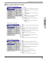
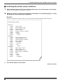
■ Other functions (Menu functions)
“Setup Tags/Logs” submenu
New
Creates a new setup file of tags and logs.
Open
Opens a file in which tags and logs have
been stored.
Save
Overwrites a file in which tags and logs
have been set.
Preparing for
Measurement
Save As
Saves a file in which tags and logs have
been set under a new file name.
Send
Transmits the tag and log setup data to
the main unit.
Print
Outputs the tag and log setup data for
the printer.
“Setup Persons” submenu
New
Creates a new file for setting up operator names.
Open
Opens a file in which operator names have been stored.
Save
Overwrites a file in which operator names have been set.
Save As
Saves a file in which operator names have been
set under a new file name
Close
Closes the operator name setup screen.
Send
Transmits the operator name data file currently
opened to the main unit.
Print
Outputs the operator name data for the printer.
“Setup Comment” submenu
New
Creates a new file for setting up comment.
Open
Opens a file in which comment have been stored.
Save
Overwrites a file in which comment have been set.
Save As
Saves a file in which comment have been set
under a new file name
Close
Closes the comment setup screen.
Send
Transmits the comment data file currently
opened to the main unit.
Print
Outputs the comment data for the printer.
IM 54011-E
21
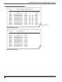
3 Setting Up with the Personal Computer
“Measured Datas” submenu
Save As
Saves the measurement data in a text format.
Close
Closes the measurement data file.
Transfer
Transfers the measurement data file to Excel.
Print
Outputs the measurement data to the printer.
“Tag/Log Table” submenu
New
Opens a new blank tag/log table.
Open
Opens an existing tag/log table.
Save
Saves the changes to the open tag/log table.
Save As
Saves the open tag/log table under a new
filename.
Select Reference Table
Selects the reference tag/log table. Based on
this reference table, abbreviated names will be
replaced with the respective full names.
Clear Reference Table
Clears the selection of reference tag/log table.
Forward to Tag/Log Setup File
Forwards the settings in the open tag/log table to
the setup file.
“Person Table” submenu
New
Opens a new blank person table (a list of
operators).
Open
Opens an existing person table.
Save
Saves the changes to the open person table.
Save As
Saves the open person table under a new
filename.
Select Reference Table
Selects a person table. Based on this person
table, abbreviated person names will be
replaced with the respective full names.
Clear Reference Table
Clears the selection of reference person table.
Forward to Person Setup File
Forwards the settings in the open person table to
the setup file.
22
IM 54011-E
3 Setting Up with the Personal Computer
“Comment Table” submenu
New
Opens a new blank comment table.
Open
Opens an existing comment table.
Save
Saves the changes to the open comment table.
Save As
Saves the open comment table under a new
filename.
Select Reference Table
Selects a comment table. Based on this
comment table, abbreviated comment names will
be replaced with the respective full names.
Preparing for
Measurement
Clear Reference Table
Clears the selection of reference comment table.
Forward to Comment Setup File
Forwards the settings in the open comment table
to the setup file.
“Voltage Range Settings” submenu
New
Opens a new blank voltage setting file.
Open
Opens an existing voltage setting file.
Save
Saves the changes to the open voltage setting file.
Save As
Saves the open voltage setting file under a new
filename.
Send
Sends (downloads) the settings in the open voltage
setting file to the TM20.
Receive
Receives (uploads) the voltage measurement
settings inside the TM20.
“Comm” menu
Properties
Set the conditions required to communicate with the personal
computer. Below are the setup items
• Communication port
• Baud rate
• Parity
• Data bits
• Stop bits
Receive
Receives from the main unit the measured temperature data and
other data set with the main unit.
IM 54011-E
23
3 Setting Up with the Personal Computer
“Edit” menu
Cut
Moves the currently selected data to the pasteboard.
Copy
Copies the currently selected data to the pasteboard.
Paste
Copies the data recorded in the pasteboard to the selected
location on the screen.
Delete
Deletes the currently selected data.
Select All
Sets all the data on the currently selected box to the selected
condition.
Column and Row (usable only in tag/log table, person table
and comment table.)
Add / insert / delete column or row, and modify column’s name.
Sort (usable only in tag/log table, person table and comment
table.)
Performs data sorting in the columns of “Abbr. Name” and
“Full name”.
Mark (usable only in tag/log table, person table and comment
table.)
Selects “Select All” or “Cancel All” of the selected settings
high lighted in yellow for transmitting to the setting file etc.
[TIP]
Measurement data received from the main unit cannot be edited using the “Edit” menu functions.
“Display” menu
Tool Bar
Switches on and off the toolbar display (button icon allowing
one-touch operation).
Status Bar
Switches on and off the status bar display (a region in which the
date and time are displayed).
“Help” menu
Model
Displays model code of the Thermo-Collector in use.
About Thermo-Collector...
Displays the version information of the Thermo-Collector
software.
24
IM 54011-E
3 Setting Up with the Personal Computer
■ Other functions (Tool icons functions)
For efficiency, single-click on any of the tool icons to instantly execute the assigned function.
Creates a new setup file of tags and logs.
This function is the same as “New” in the
“Setup Tags/Logs” submenu of the “File”
menu.
Transmits the comment data currently displayed on the screen to the main unit. This
function is the same as “Send” in the “Setup
Comments” submenu of the “File” menu.
Loads a file of stored tags and logs. This
function is the same as “Open” in the “Setup
Tags/Logs” submenu of the “File” menu.
Loads the measured data file that has been
saved. This function is the same as “Open”
in the “ Measured Datas” submenu in the
“File” menu.
Saves the tag and log setup data file so it
overwrites the existing file. This function
is the same as “Save” in the “Setup Tags/
Logs” submenu of the “File” menu.
Creates a new file for setting operator
names. This function is the same as “New”
in the “Setup Persons” submenu of the
“File” menu.
Loads the operator name file that has been
saved. This function is the same as “Open”
in the “Setup Persons” submenu of the
“File” menu.
Forwards the settings in the open tag/log
table to the setup file. This function is the
same as “Forward to Tag/Log Setup File”
in the “Tag/Log Table” submenu in the
“File” menu.
Saves the operator name file so it overwrites
the existing file. This function is the same
as “Save” in the “Setup Persons” submenu
of the “File” menu.
Forwards the settings in the open person
table to the person setup file. This function
is the same as “Forward to Person Setup
File” in the “Person Table” submenu in the
“File” menu.
Transmits the operator name data currently
displayed on the screen to the main unit.
This function is the same as “Send” in the
“Setup Persons” submenu of the “File”
menu.
Forwards the settings in the open comment
table to the comment setup file. This function is the same as “Forward to Comment
Setup File” in the “Comment Table”
submenu in the “File” menu.
Saves the measured data in a text format file.
This function is the same as “Save As” or
“Save” in the “Measured Datas” submenu
of the “File” menu.
Receives the data from the main unit. This
function is the same as “Receive” in the
“Comm” menu.
Creates a new file for setting comments.
This function is the same as “New” in the
“Setup Comments” submenu of the “File”
menu.
Loads the comment file that has been saved.
This function is the same as “Open” in the
“Setup Comments” submenu of the “File”
menu.
Save the comment file so it overwrites the
existing file. This function is the same as
“Save” in the “Setup Comments” submenu
of the “File” menu.
IM 54011-E
Outputs the measurement data received in
association with the specified tag and log
to the printer. This function is the same as
“Print” in the “Measured Datas” submenu
of the “Comm” menu.
Moves the currently selected data to the
pasteboard. This function is the same as
“Cut” in the “Edit” menu.
Copies the currently selected data to the
pasteboard. This function is the same as
“Copy” in the “Edit” menu.
Copies the data recorded in the pasteboard
to the currently selected location on the
screen. This function is the same as “Paste”
in the “Edit” menu.
25
Preparing for
Measurement
Transmits the tag and log setup data currently selected to the main unit. This function is the same as “Send” in the “Setup
Tags/Logs” submenu of the “File” menu.
Transfers the measurement data which is
going to the personal computer to Microsoft
Excel. This function is the same as “Transfer” in the “Measured Datas” submenu of
the “File” menu.
3 Setting Up with the Personal Computer
3.3 Files created on a computer for settings of TM20
Tables of settings for creating setup files.
Each table contains settings required for measurement.
Files that contain settings to be written
(downloaded) to a TM20.
Tag/log table i
Setup file 1
Many setup files can
be created from the same
tag/log table.
Setup file 2
Select Reference Table
Select a tag/log table. Based on this tag/log table,
abbreviated names will be replaced with the respective full names.
Abbreviated tag and log names can be replaced with the respective full names.
Person table j
Person setting 1
Person setting 2
Person setting 3
Select Reference Table
Abbreviated person names can be replaced with the respective full names.
Comment table k
Comment setting 1
Comment setting 2
Select Reference Table
Abbreviated comment names can be replaced with the respective full names.
Tag/log tables, person tables, and comment tables.
Used previously to make a variety of measurement settings as lists of the respective settings.
By simply choosing an entry from each table, you can create a setup file for your TM20.
Setup files, person settings, and comment setting.
Files containing settings to be written (downloaded) to a TM20.
26
IM 54011-E
3 Setting Up with the Personal Computer
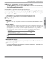
3.4 Setups required to use collector function (setting tag names,
alarms, name of person, and comment, and selecting input
channel(s))
To use the collector function, you need to set the tags in advance. A convenient way to do so
is to create a table of tags and logs, namely, a tag/log table. Once you create a tag/log table
and set it to the reference table, Thermo-Collector automatically replaces abbreviated tag
names* with more descriptive full names** when receiving the measured data from a TM20.
* Abbreviated names are 8-digit names that can be displayed on the TM20 screen.
** Full names can be displayed on the PC screen without any limitation in length.
■ Setup contents
● Tag name
● Input channel
Thermo-Collector has multiple input channels and probes for measuring temperatures of
substances in a vapor, solid, or liquid phase. Since the probe to be used depends on the
measuring object, it is necessary to set the available input channel on a tag in advance.
The following table shows the probe types and their corresponding input channels.
Probe type
Thermocouple types K, J, E, and T
±100 mV or ±1 V voltage output sensor (See TIP below.)
Input channel
A, B
[TIP]
To plug a voltage output sensor into channel A or B, use a U-shaped omega connector.
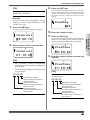
● Alarm
Set a limit temperature at which the alarm sounds.
• ON/OFF of the upper-limit alarm and upper-limit temperature
Make the following settings to sound an alarm when the temperature rises above a preset limit.
The upper-limit temperature cannot be set if the alarm function for the upper limit is set to OFF.
Setting the upper-limit alarm to ON and the upper-limit temperature to 70°C
Temperature
70°C
: Range in which the alarm sounds.
IM 54011-E
27
Preparing for
Measurement
Put a title for each tag.
3 Setting Up with the Personal Computer
• ON/OFF of the lower-limit alarm and lower-limit temperature
Make the following settings to sound an alarm if the temperature falls below a preset limit.
The lower-limit temperature cannot be set if the alarm function for the lower limit is set to OFF.
Setting the lower-limit alarm to ON and the lower-limit temperature to 50°C
Temperature
50°C
: Range in which the alarm sounds
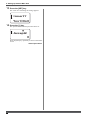
• Inverse alarm function ON/OFF
The settings of the alarm function can be inverted.
Specifically, if this inverse alarm functions is set to ON, an alarm will sound if the temperature falls
below the upper limit or if the temperature rises above the lower limit.
If “OFF”
If “ON”
Upper-limit alarm
Lower-limit alarm
70°C
50°C
Upper-limit alarm
Lower-limit alarm
Temperature
Temperature
70°C
70°C
50°C
50°C
70°C
50°C
: Range in which the alarm sounds
[TIP]
The alarm can also be set to turn off if the temperature exceeds the upper limit, or it can be set to turn
on if the temperature falls between the upper and lower limits.
● Operator name
Set the name of the operator.
See Also
For how to set the operator name, refer to “■ Registering the measurement operator name”.
28
IM 54011-E
3 Setting Up with the Personal Computer
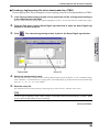
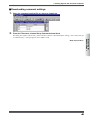
■ Setting tags
● Make settings using a tag/log table
A variety of tag settings can be set beforehand in a table, and from the table, you can select
settings to be downloaded to a TM20 as appropriate.
1.
Run Thermo-Collector.
After the Thermo-Collector main window opens, a document window entitled “Setup Tag/Logs - New” opens in it.
2.
From the File menu, choose Tag/Log Table then New to open the Tag/Log Table window
(a document window).
Tag/Log Table window
Enter the tag names in the Abbr. Name column with a maximum of eight alphanumeric
characters (for example, Burger).
4.
In the Full Name column, enter more descriptive tag names.
There is no limitation in length with full names. If you select this table as the reference tag/log table, ThermoCollector will replace the abbreviated names with the corresponding full names based on this table when receiving
measured data from a TM20.
IM 54011-E
29
Preparing for
Measurement
3.
3 Setting Up with the Personal Computer
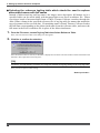
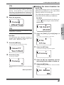
5.
Double-click in the “Channel” column.
The specified tag name is set and the pull-down menu appears.
6.
Select either A, B, D, or AB.
The specified channel is set.
7.
Click in the “Upper Limit” column
The cursor moves to a cell for the “Upper Limit”.
8.
Enter the “Upper Limit” with numeric characters (Example: 150.0).
[TIP]
Enter a value that does not exceed “Upper Limit” of the probe used for actual measurement. The
“Upper Limit” that can be measured varies according to the probe used for measurement.
The specified upper-limit temperature has been set.
30
IM 54011-E
3 Setting Up with the Personal Computer
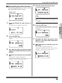
9.
Double-click in the “Hi Alarm” column.
The pull-down menu appears.
10. Select either ON or OFF.
11. Click in the “Lower Limit” column.
The upper-limit alarm ON/OFF setting is made and the cursor moves to the “Lower Limit” column.
Preparing for
Measurement
12. Enter the “Lower Limit” with numeric characters (Example: 135.0).
[TIP]
Enter a value that does not fall below the “Lower Limit” of the probe used for the actual measurement.
The “Lower Limit” that can be measured varies according to the probe used for the measurement.
The specified lower-limit temperature has been set.
13. Double-click in the “Lo Alarm” column.
The pull-down menu appears.
IM 54011-E
31
3 Setting Up with the Personal Computer
14. Select either ON or OFF.
The lower-limit alarm ON/OFF setting is made.
15. Click in the “Turn Alarm” column.
The pull-down menu appears.
16. Select either ON or OFF.
The alarm condition is set.
You can insert and add rows by either of the following ways:
•
Using a shortcut menu that opens by a right-click
•
Using keystrokes of CTRL+I and CTRL+R
Repeat steps 3-16 to set as many tags as necessary.
17. Save the table.
From the “File” menu, choose “Tag/Log Table” then “Save As” to save the table.
-End of procedure-
32
IM 54011-E
3 Setting Up with the Personal Computer
● Creating a tag/log setup file to be downloaded to a TM20
From a tag/log table, select settings to create a tag/log setup file to be downloaded to a TM20.
1.
In the Tag/Log Table window, double-click to select the cell No. of a tag whose setting is
to be downloaded to the TM20.
The row of the selected tag setting then appears highlighted in yellow. To clear the selection, double-click it again.
2.
From the File menu, choose Setup Tags/Logs then New to open the Setup Tags/Logs
window of a blank setup file.
3.
Click
. The selected tag setting is then copied to the Setup Tags/Logs window.
Preparing for
Measurement
Tag/log table
4.
Setup file
Select the measurement range.
The measurement range is selected as “K” (meaning thermocouple type K) by default. To set to a different range,
click “Channel A” or “Channel B” box, as appropriate, in the Setup Tags/Logs window and choose the desired range
from “K”, “J”, “E”, “T”, “1V”, and “100mV”.
5.
Save the setup file.
The setup file can be saved by choosing “Setup Tags/Logs” then “Save As” from the “File” menu.
[TIP]
A row of data in which the Abbr. Name column is left blank cannot be downloaded to a TM20. Make
sure the abbreviated names are set for all tags.
-End of procedure-
IM 54011-E
33
3 Setting Up with the Personal Computer
● Selecting the reference tag/log table which should be used to replace
abbreviated names with full names
Instead of abbreviated tag and log names, the longer, more descriptive full names set in a
specified table can be stored along with measured data to an Excel worksheet file. When
receiving a batch of measured data from a TM20, Thermo-Collector searches through the
Abbr. Name column in the specified reference file of tag/log table for names that match the
tag or log names of the received data. If a matching name is found, Thermo-Collector fetches
the full name corresponding to the abbreviated name from the reference table, and stores the
full name in the Excel worksheet file in place of the abbreviated name.
1.
From the File menu, choose Tag/Log Table then Select Reference Table.
Then, select the reference table in the dialog box that appears.
2.
Click Yes to confirm the selection.
Once the reference table is selected, its filename is displayed in the lower-left of the window and the aforementioned
automatic name replacement will take place.
[TIP]
Of course, you can directly set entries in a setup file instead of copying settings from a tag/log table.
Next, proceed to operator name setting.
- End of procedure -
34
IM 54011-E
3 Setting Up with the Personal Computer
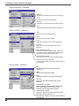
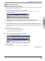
■ Setting operator names
● Make settings with a person table
A person table is a list of the set operator names. It is possible at any time to select whichever
settings from a person table you want.
1.
From the File menu, choose Person Table, then New.
A document window for setting operator names, entitled “Person Table - New” as shown below, then opens.
Person Table window
In the Abbr. Name column, enter operator names of up to eight characters.
Abbreviated names stand for shortened operator names of up to 8 alphanumeric characters that can be displayed on
the TM20 screen.
3.
In the Full Name column, enter the longer, more descriptive names of the operator.
Full names have no limitation in length. If you select this table as the reference person table, Thermo-Collector will
replace the abbreviated names with the corresponding full names based on this table when receiving measured data
from a TM20.
4.
Add and insert rows as necessary.
You can insert and add rows by either of the following ways:
5.
•
Using a shortcut menu that opens by a right-click
•
Using keystrokes of CTRL+I and CTRL+R
Click the Abbr. name cell of the next row and set.
Enter the abbreviated and full names again.
6.
Save the table.
From the File menu, choose Person Table then Save As to save the table.
- End of procedure -
IM 54011-E
35
Preparing for
Measurement
2.
3 Setting Up with the Personal Computer
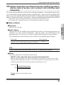
● Creating a person setup file to be downloaded to a TM20
From a person table, select settings to create a person setup file to be downloaded to a TM20.
1.
In the Person Table window, double-click to select the cell No. of an entry which is to be
downloaded to the TM20.
The row of the selected entry then appears highlighted in yellow. To clear the selection, double-click it again.
2.
From the File menu, choose Setup Persons then New to open the Setup Persons window of a blank setup file.
3.
Click
. The selected operator name entry is then copied to the Setup Persons
window.
- End of procedure -
● Selecting the reference person table which should be used to replace
abbreviated names with full names
1.
From the File menu, choose Person Table then Select Reference Table.
Then, select the reference table in the dialog box that appears.
When receiving a batch of measured data from a TM20, Thermo-Collector searches through the Abbr. Name column
in the specified reference file of person table for names that match the operator names of the received data. If a
matching name is found, Thermo-Collector fetches the full name corresponding to the abbreviated name from the
reference table, and stores the full name in the Excel worksheet file in place of the abbreviated name.
Once the reference table is selected, its filename is displayed in the lower-middle part of the window and the aforementioned automatic name replacement will take place.
[TIP]
• The person table can be saved by choosing Person Table then Save As from the File menu.
• Of course, you can directly set entries in a setup file instead of copying settings from a person table.
36
IM 54011-E
3 Setting Up with the Personal Computer
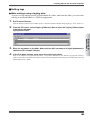
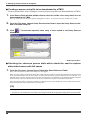
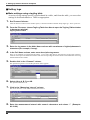
■ Setting comments
Comments for recording in a TM20 can be set. Up to 32 previously set comments can be
stored in the memory of a TM20 together with each measured value. For example, setting a
comment describing the action taken when the result of measurement is no good, such as
“Re-measure” or “Discard,” records the action that was performed consequently.
● Setting comments in a new comment table
1.
From the File menu, choose Comment Table, then New.
A document window titled “Comment Table,” as shown below, then opens.
Comment Table window
Enter comments.
Abbreviated comments can be up to eight characters long, whereas there is no limit to the number of characters for
full names. Set a descriptive comment for each full name. When uploading measured data from a TM20 to the PC,
the abbreviated comments are replaced with the corresponding full names.
Rows can be added and inserted using commands on the shortcut menu which opens by a right-click, or by using the
keystrokes CTRL+R and CTRL+I.
3.
Save the comment table.
To save the table of comments you set, click “File” and choose “Comment Table” then “Save As”.
- End of procedure -
IM 54011-E
37
Preparing for
Measurement
2.
3 Setting Up with the Personal Computer
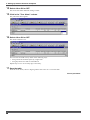
● Creating a comment setting file
Select a comment from a comment table and write (download) it to the connected TM20.
1.
In the Comment Table window, double-click to select the comment to be set in the
TM20.
The row of the selected comment setting then appears highlighted in yellow. To clear the selection, double-click it
again.
2.
Then, click
. The selected comment is then copied to the Setup Comments win-
dow.
- End of procedure -
● Selecting a reference table for replacing abbreviated comments with full
comments
1.
From the File menu, choose Comment Table then Select Reference Table.
Selecting the reference comment table enables the following automatic replacement.
When importing a batch of measured data from the TM20 into an Excel worksheet file, Thermo-Collector searches
through the Abbr. Comment column in the specified comment list file for those that match the comments in the
received data. If it is found, Thermo-Collector fetches the full comment corresponding to the abbreviated comment
from the list, and stores that full comment in the Excel worksheet file instead of the abbreviated comment.
Once the reference comment list file is selected, its filename is displayed in the lower left of the window.
- End of procedure -
● Downloading comments to TM20
To load the comments which have been set, click
38
.
IM 54011-E
3 Setting Up with the Personal Computer
3.5 Setups required to use the logging function
(setting the log name, input channel, measurement interval,
and measurement period)
Settings relating to the logging function must be made here.
A convenient way to do so is to create a table of tags and logs, namely, a tag/log table. Once
you create a tag/log table and set it to the reference table, Thermo-Collector automatically
replaces abbreviated tag names* with more descriptive full names** when receiving the
measured data from a TM20.
* Abbreviated names are 8-digit names that can be displayed on the TM20 screen.
** Full names can be displayed on the PC screen without any limitation in length.
■ Setup contents
Put a title to each log. A log name can consist of a maximum of eight alphanumeric characters.
● Input channel
Thermo-Collector has multiple input channels and probes for measuring temperatures of
substances in a vapor, solid, or liquid phase. Since the probe to be used depends on the
measuring object, it is necessary to set the available input channel on a tag in advance.
The following table shows the probe types and their corresponding input channels.
Probe type
Thermocouple types K, J, E, and T
±100 mV or ±1 V voltage output sensor (See TIP below.)
Input channel
A, B
[TIP]
To plug a voltage output sensor into channel A or B, use a U-shaped omega connector.
●Measurement interval
Set an interval at which the temperature is periodically measured. The interval can be set to
between 1 second to 24 hours.
●Measurement period
Set a period through which the temperature is measured continuously. The period can be
set to between 1 second to 999 days.
IM 54011-E
39
Preparing for
Measurement
●Log name
3 Setting Up with the Personal Computer
■ Setting logs
● Make settings using a tag/log table
A variety of tag settings can be set beforehand in a table, and from the table, you can select
settings to be downloaded to a TM20 as appropriate.
1.
Run Thermo-Collector.
After the Thermo-Collector main window opens, a document window entitled “Setup Tag/Logs - New” opens in it.
2.
From the File menu, choose Tag/Log Table then New to open the Tag/Log Table window
(a document window).
Tag/Log Table window
3.
Enter the log names in the Abbr. Name column with a maximum of eight alphanumeric
characters (for example, Convey).
4.
In the Full Name column, enter more descriptive tag names.
There is no limitation in length with full names. If you select this table as the reference tag/log table, ThermoCollector will replace the abbreviated names with the corresponding full names based on this table when receiving
measured data from a TM20.
5.
Double-click in the “Channel” column.
The specified log name is set and the pull-down menu appears.
6.
Select either A, B, D, or AB.
The specified channel is set.
7.
Click in the “Measuring interval” column.
The cursor moves to a cell for the measurement interval.
8.
40
Enter the measurement interval with numeric characters and colons “:” (Example:
00:10:00).
IM 54011-E
3 Setting Up with the Personal Computer
[TIP]
Use numeric characters and colons to enter a measurement interval. The input range is: hh < 25, mm
< 60, and ss < 60, where “hh” denotes hours, “mm” denotes minutes, and “ss” denotes seconds.
All the interval data must be eight characters or less (i.e. “hh:mm:ss”. h, m, and s are optional numeric
characters).
The specified measurement interval has been set.
9.
Click in the “Measuring period” column.
Enter the measurement period with numeric characters, a backslash, and colons
(Example: 003/20:30:00).
[TIP]
The specified measurement period has been set.
You can insert and add rows by either of the following ways:
•
Using a shortcut menu that opens by a right-click
•
Using keystrokes of CTRL+I and CTRL+R
10. Save the table.
From the “File” menu, choose “Tag/Log Table” then “Save As” to save the table.
-End of procedure-
IM 54011-E
41
Preparing for
Measurement
Use numeric characters, a backslash, and colons to enter a measurement period. The input range is:
ddd < 1000, hh < 24, mm < 60, and ss < 60, where “ddd” denotes the number of days, “hh” denotes
hours, “mm” denotes minutes, and “ss” denotes seconds.
All the period data must be twelve characters or less (i.e. “ddd:hh:mm:ss”. d, h, m, and s are optional
numeric characters).
3 Setting Up with the Personal Computer
3.6 Downloading the setup data to the main unit
If the setup operation for the personal computer has been completed, download the setup
data of the tag, log, and operator name to the main unit.
Tag setup data and log setup data is downloaded in a batch and as one file. The operator data
is downloaded separately.
NOTE
If the setup data is downloaded to the main unit, the setup data and measurement data
that existed in the main unit before download is deleted.
■ Preparation for downloading
1.
Confirm that the power to the personal computer and main unit is OFF.
2.
Connect the personal computer and main unit with the supplied cable.
See Also
For how to connect the personal computer and main unit, refer to “■ Connecting the personal computer and main unit” in Section 3.1.
3.
Turn on the power of the main unit.
See Also
For how to turn on the power to the main unit, refer to Chapter 4, “Turn ON/OFF of the Power Supply”
in the “Before Use” part.
4.
Turn on the power of the personal computer.
Now it is ready for downloading.
-End of procedure-
42
IM 54011-E
3 Setting Up with the Personal Computer
■ Downloading the tag and log setup data to the personal computer
1.
Initiate Thermo-Collector software.
After the main screen of Thermo-Collector software has been displayed, the “Setup Tags/Logs - New” screen is
displayed.
2.
Load a file in which the tag and log setup data is stored.
See Also
For how to load a file containing tag and log data, refer to “■ Loading a file containing the setup data”
in Section 3.2.
Preparing for
Measurement
3.
Select “Send” in the “Setup Tags/Logs” submenu accessed from the “File” menu.
The confirmation dialog box appears.
4.
Click on the [OK] button.
A dialog box indicating the progress of data downloading is displayed. At the same time, “Communicating ...” is
displayed on the main unit.
After the downloading of the tag and log setup data has been completed, the screen indicating the progress of data
downloading and the screen displaying the “Communicating ...” message on the main unit disappears.
-End of procedure-
IM 54011-E
43
3 Setting Up with the Personal Computer
■ Downloading the measurement operator name data
1.
Load a file in which the operator name to be downloaded is stored.
See Also
For how to load a file containing operator names, refer to “■ Loading a file containing the setup data”
in Section 3.2.
2.
Select “Send” in the “Setup Persons” menu accessed from the “File” menu.
A dialog box indicating the progress of downloading is displayed.
At the same time, “Communicating ...” is displayed on the main unit.
After the downloading of the operator data has been completed, the screen indicating the progress of data downloading and the screen displaying the “Communicating...” message on the main unit disappears.
-End of procedure-
44
IM 54011-E
3 Setting Up with the Personal Computer
■ Downloading comment settings
1.
Open the comment setting file you want to download.
2.
From the File menu, choose Setup Comments then Send.
The dialog box appears and informs you that Thermo-Collector is downloading the settings. At the same time, the
“Communicating...” message appears on the TM20’s LCD.
IM 54011-E
45
Preparing for
Measurement
- End of procedure -
4 Setting Up with the Main Unit
4
Setting Up with the Main Unit
4.1 Setups required to use col-
2.
A screen for selecting the tag name appears.
lector function (setting tag
names, alarms, name of
person, and comment, and
selecting input channel(s))
Burger
0
Before using the collector function, the following tag setups must be made.
[TIP]
■ Setup contents
If no tag has been created in the main unit,
[NewTag] is displayed on the screen.
See Also
For information about each setup item, refer to
Section 3.4, “Setups required to use collector
function (settintg tag names, alarms, name of
person, and comment, and selecting input
channel(s))”.
•
•
•
•
•
Tag name
Input channel
Alarm
Operator name
Comment
Press the [SET] key.
3.
Press the [▼] key repeatedly until
[NewTag] is displayed on the screen.
[NewTag]
0
4.
Use the [CH] key to select the input
channel.
The input channel of the [INPUT] gage changes.
■ Creating a new tag
Create new tags for recording the measurement data.
[NewTag]
Home screen
1.
0
18:54:27
[TIP]
22225.9°C
Select “A” and “B” at the two-channel simultaneous measurement.
Press the [FUNC], [1], and [3] keys, in
order.
The “Tag Ins” screen appears.
5.
Press the [SET] key.
A screen for entering a new tag name appears.
F13
Ta g I n s
46
[ N e w Ta g ]
IM 54011-E
4 Setting Up with the Main Unit
[TIP]
If a new tag is created while [NewTag] is displayed, the created tag is added to the end of
the list. If the [SET] key is pressed while
[NewTag] is not displayed, the created tag is
inserted immediately before the selected tag.
6.
■ Setting the alarm function for
each tag
The alarm function can be set according to
different tag conditions, or the same alarm
function can be set for all tags.
The following procedure is used to set the
alarm function for different conditions.
Enter the tag name.
See Also
To set the same alarm function for all tags, proceed to “■ Batch-setting the alarm function”.
Convey
Home screen
[ N e w Ta g ]
22225.9°C
A tag name can consist of a maximum of eight
alphanumeric characters.
1.
See Also
The “1File” screen appears on the LCD.
For information about entering a character or
number, refer to Chapter 6, “How to Input Characters” in the “ Before Use” part.
7.
F72
Press the [SET] key.
1File
A screen asks you to confirm the setting.
2.
Insert?
Press the [FUNC], [7], and [2] keys, in
order.
Press the [SET] key.
A screen for selecting a tag name appears.
Ye s 1 / N o 0
Convey
8.
Press the [1] key.
0
A new tag is created.
Convey
0
Press the [ESC] key repeatedly to return to the Home
screen.
-End of procedure-
3.
Press the [▼] key repeatedly until the
desired tag name number is called up.
4.
Press the [SET] key.
A screen for setting the “Hi Alarm” function ON/OFF
appears.
Hi Alarm
ON
IM 54011-E
47
Preparing for
Measurement
18:54:27
[TIP]
4 Setting Up with the Main Unit
5.
6.
Use either the [▼] or [▲] key to set the
upper-limit temperature alarm function
ON/OFF.
Lo Alarm
If ON has been selected, press the [SET]
key.
0000.0°C
The “Hi Alarm” setting screen appears.
If OFF has been selected in step 5, this screen will
not appear. In this case proceed to step 8.
Hi Alarm
0000.0°C
7.
11. Enter the lower-limit temperature.
Lo Alarm
0020.0°C
[TIP]
Enter the upper-limit temperature.
Hi Alarm
0020.0°C
To set a negative value, press either the [▼] or
[▲] key. “0” on the screen will change to a
“-” symbol.
12.Press the [SET] key.
The specified lower-limit temperature is set and the
“Turn” screen appears.
[TIP]
To set a negative value, press either the [▼] or
[▲] key. “0” on the screen will change to a
“-” symbol.
Turn
OFF
8.
Press the [SET] key.
The specified upper-limit temperature is set and the
screen for setting the “Lo Alarm” function ON/OFF
appears.
Lo Alarm
ON
9.
Use either the [▼] or [▲] key to set the
lower-limit temperature alarm function
ON/OFF.
10. If “ON” has
been selected, press the
13.Use either the [▼] or [▲] key to select
whether the operation of the alarm function is to be inverted. If ON is selected,
the alarm function will operate under the
inverse conditions.
14.Press the [SET] key.
The range in which the alarm sounds is displayed.
Then, the screen asks you to confirm the setting.
Change?
Ye s 1 / N o 0
[SET] key.
The “Lo Alarm” setting screen appears.
If “OFF” has been selected in step 9, this screen will
not appear. In this case proceed to step 12.
15.Press the [1] key.
The alarm function is set for each tag.
Press the [ESC] key repeatedly to return to the Home
screen.
-End of procedure-
48
IM 54011-E
4 Setting Up with the Main Unit
■ Batch-setting the alarm function
5.
The following procedure is used to set the
same alarm function for all tags.
Hi Alarm
0020.0°C
Home screen
1.
18:54:27
[TIP]
22225.9°C
To set a negative value, press either the [▼] or
[▲] key. “0” on the screen will change to a
“-” symbol.
Press the [FUNC], [7], and [1] keys, in
order.
The “All File” screen appears on the LCD.
6.
File
Lo Alarm
ON
Press the [SET] key.
A screen for setting the “Hi Alarm” function ON/OFF
appears.
Hi Alarm
ON
3.
Use either the [▼] or [▲] key to set the
upper-limit temperature alarm function
ON/OFF.
4.
If ON has been selected, press the [SET]
key.
The “Hi Alarm” setting screen appears.
If OFF has been selected in step 3, this screen will
not appear. In this case proceed to step 6.
7.
Use either the [▼] or [▲] key to select
ON/OFF of the lower-limit temperature
alarm function.
8.
When ON has been selected, press the
[SET] key.
The “Lo Alarm” setting screen appears.
If OFF has been selected in step 7, this screen will
not appear. In this case proceed to step 10.
Lo Alarm
0000.0°C
Hi Alarm
0000.0°C
IM 54011-E
49
Preparing for
Measurement
All
Press the [SET] key.
The specified upper-limit temperature is set and the
screen of selecting ON/OFF of the “Lo Alarm” function appears.
F71
2.
Enter the upper-limit temperature.
4 Setting Up with the Main Unit
9.
Enter the lower-limit temperature.
■ Registering the measurement
operator name
Home screen
Lo Alarm
0020.0°C
18:54:27
22225.9°C
[TIP]
In order to set a negative value, press either
the [▼] or [▲] key. “0” on the screen will
change to a “-” symbol.
1.
10.Press the [SET] key.
F83
The specified lower-limit temperature is set and the
“Turn” screen appears.
Turn
Press the [FUNC], [8], and [3] keys, in
order.
Entry
2.
Press the [SET] key.
A screen for registering an operator name appears.
OFF
1
11.Use either the [▼] or [▲] key to select
12.
whether the operation of the alarm function is to be inverted. If ON is selected,
the alarm function will operate under the
inverse condition.
Press the [SET] key.
The range in which the alarm sounds is displayed.
Then, the screen asks you to confirm the setting.
Smith
3.
Press the [▼] key repeatedly until the
desired operator name number is called
up.
2
Change?
Ye s 1 / N o 0
[TIP]
13.Press the [1] key.
The range in which the alarm function is active is set
for all tags as a batch.
Press the [ESC] key repeatedly to return to the Home
screen.
[TIP]
If another alarm function is batch-set for all
tags after one alarm function has been batchset, only the latest one is effective.
Up to 10 operators, which are serially numbered, can be set in a TM20.
See Also
For how to enter letters and numbers, refer to
Chapter 6, “How to Input Characters” in the
“Before Use” part.
-End of procedure-
50
IM 54011-E
4 Setting Up with the Main Unit
4.
Press the [SET] key.
2.
5.
Enter the operator name with a maximum of eight characters.
Press the [SET] key.
A screen for setting comments then appears.
1
2
Discard
3.
See Also
Press the [▼] key repeatedly until the
desired comment number is called up.
For how to enter a character or number, refer
to Chapter 6, “How to Input Characters” in the
“Before Use” part.
Press the [SET] key.
The screen for confirming the settings appears.
[TIP]
Up to 32 comments, which are serially numbered, can be set in a TM20.
Entry?
Ye s 1 / N o 0
See Also
7.
For how to enter letters and numbers, refer to
Chapter 6, “How to Input Characters,” in the
“Before Use” part.
Press the [1] key.
The specified operator name has been set.
Press the [ESC] key repeatedly to return to the Home
screen.
4.
Press the [SET] key.
5.
Enter a comment of up to 8 characters.
-End of procedure-
■ Setting comments
Home screen
2
18:54:27
22225.9°C
1.
6.
The screen asks you to confirm the setting.
Press the [FUNC], [0], and [2] keys in
order.
Entry?
Ye s 1 / N o 0
F02
Comment
Press the [SET] key.
7.
Press the [1] key.
The comment is then set.
Press the [ESC] key repeatedly to return to the home
screen.
- End of procedure -
IM 54011-E
51
Preparing for
Measurement
6.
2
4 Setting Up with the Main Unit
4.2 Setups required to use the
logging function
(setting the log name, input
channel, measurement interval, and measurement
period)
[TIP]
If no log has been created in the main unit,
[NewLog] is displayed on the screen.
3.
Press the [▼] key repeatedly until
[NewLog] appears on the screen.
[NewLog]
Before using the logging function, it is necessary to make logs settings.
0
■ Setup contents
See Also
For more information about each setup item,
refer to Section 3.2, “Setups required to use
the log (Setting the log name, input channel,
measurment interval, and measurement period)”
•
•
•
•
4.
The channel indication below “INPUT” changes accordingly.
Log name
Input channel
Measurement Interval
Measurement period
[NewLog]
0
[TIP]
■ Operation procedure
Select “A” and “B” at the two-channel simultaneous measurement.
Home screen
18:54:27
Use the [CH] key to select the input
channel.
5.
Press the [SET] key.
A screen for entering a new log name appears.
22225.9°C
1.
Press the [FUNC], [2], and [3] keys, in
order.
[ N ew L o g ]
The “Log Ins” screen appears on the LCD.
[TIP]
F23
If a new log is created while [NewLog] is displayed, the created log is added to the end of
the list. If the [SET] key is pressed while
[NewLog] is not displayed, the created log is
inserted immediately before the selected log.
Log Ins
2.
Press the [SET] key.
A screen for selecting the log name appears.
Accept1
Enter the log name.
Accept2
0
52
6.
[ N ew L o g ]
IM 54011-E
4 Setting Up with the Main Unit
9.
[TIP]
A log name can consist of a maximum of eight
alphanumeric characters.
Press the [SET] key.
The specified measurement interval is set and the
screen for setting the measurement period (select the
number of days from the options, which also includes
the number of hours, minutes, and seconds) is displayed.
See Also
For how to enter letters and numbers, refer to
Chapter 6, “How to Input Characters” in the
“Before Use” part.
7.
ProdDay
002
Press the [SET] key.
A screen for setting the measurement interval appears.
10. Enter the number of days.
Inter val
8.
The screen for setting the measurement period (select the
number of hours, minutes and seconds from the options,
which also includes the number of days) is displayed.
Enter the hour, minute, and seconds.
ProdTime
Inter val
01:15:30
00:00:00
12. Enter the number of hours, minutes, and
seconds.
[TIP]
• Set “2 seconds” or more as measurement
interval at the two-channel simultaneous
measurement.
• The definition and range of each input value
is given below.
00:00:00
01:30:00
[TIP]
The definition and range of each input value
are given below.
Indicates the seconds.
The input range is between 0
and 59 seconds
Indicates the minutes.
The input range is between 0
and 59 minutes
Indicates the hours.
The input range is between 0
and 24 hours.
IM 54011-E
ProdTime
00:00:00
Indicates the seconds.
The input range is between 0
and 59 seconds
Indicates the minutes.
The input range is between 0
and 59 minutes
Indicates the hours.
The input range is between 0
and 23 hours.
53
Preparing for
Measurement
00:00:10
11. Press the [SET] key.
4 Setting Up with the Main Unit
13. Press the [SET] key.
The screen for confirming the settings appears.
Insert?
Ye s 1 / N o 0
14. Press the [1] key.
The specified measurement period has been set.
Accept2
0
Press the [ESC] key repeatedly to return to the Home
screen.
-End of procedure-
54
IM 54011-E
5 Confirm, Modify, Clear, or Delete the Data with the Main Unit
5
Confirm, Modify, Clear, or Delete the Data with the Main Unit
5.1 Confirming the number of 5.2 Modifying the tag name
pieces of tag data
This section explains the procedure for confirming the number of pieces of tag data.
This section explains the procedure for modifying the tag name.
Home screen
Home screen
18:54:27
18:54:27
22225.9°C
22225.9°C
1.
Press the [FUNC], [1], and [1] keys, in
order.
Press the [FUNC], [1], and [2] keys, in
order.
The “TagChnge” screen appears on the LCD.
The “Curr Tag” screen appears on the LCD.
F12
F11
TagChnge
C u r r Ta g
2.
2.
Press the [SET] key.
Press the [SET] key.
Burger
Burger
12
12
3.
3.
Press the [▼] key repeatedly until the tag to
be confirmed is displayed on the screen.
Press the [▼] key repeatedly until the
tag to be modified is displayed on the
screen.
The tag name and the measurement data recorded in
association with the tag is displayed.
Beef
Beef
5
5
Press the [ESC] key repeatedly to return to the Home
screen.
4.
Use the [CH] key to select the input
channel.
The channel indication below “INPUT” changes accordingly.
-End of procedure-
IM 54011-E
55
Preparing for
Measurement
1.
5 Confirm, Modify, Clear, or Delete the Data with the Main Unit
5.
5.3 Clearing
the measurement
data associated with the tag
Press the [SET] key.
Beef
5
6.
This section explains the procedure used to
clear the measurement data obtained with the
collector function. However, the setup data
(tag name) will not be cleared.
Enter a new tag name to be modified.
Home screen
Pork
18:54:27
5
[TIP]
22225.9°C
1.
A tag name that has not been modified is displayed. If it needs to be modified, overwrite it
with a new tag name.
The “1TagFile” screen appears on the LCD.
F41
See Also
For how to enter letters and numbers, refer to
Chapter 6, “How to Input Characters” in the
“Before Use” part.
7.
1 Ta g F i l e
2.
Burger
12
Change?
Ye s 1 / N o 0
3.
Press the [▼] key repeatedly until a tag
with measurement data that is to be
cleared is displayed on the screen.
Press the [1] key.
The tag name after modification is displayed.
Chicken
27
Pork
5
The tag name has been modified.
Press the [ESC] key repeatedly to return to the Home
screen.
-End of procedure-
56
Press the [SET] key.
Press the [SET] key.
The confirmation dialog box appears.
8.
Press the [FUNC], [4], and [1] keys, in
order.
4.
Press the [SET] key.
The confirmation dialog box appears.
TagClr?
Ye s 1 / N o 0
IM 54011-E
5 Confirm, Modify, Clear, or Delete the Data with the Main Unit
5.
1.
Press the [1] key.
Press the [FUNC], [1], and [4] keys, in
order.
The “Tag Del” screen appears on the LCD.
Chicken
0
All the measurement data of the selected tag is
cleared.
Press the [ESC] key repeatedly to return to the Home
screen.
F14
Ta g D e l
2.
Press the [SET] key.
-End of procedure-
5.4 Deleting the tag
Burger
Note
12
3.
Before deleting the tag, save the measurement data associated with the tag
to a personal computer, etc.
Once the tag has been deleted, all the
measurement data associated with the
tag is completely lost.
See Also
For how to save the measurement data, refer to
Chapter 1, “Receiving the Data on the Personal
Computer” in the “Working with Measurement
Data” part.
Chicken
0
4.
22225.9°C
Press the [SET] key.
The confirmation dialog box appears.
Delete?
Home screen
18:54:27
Press the [▼] key repeatedly until the
tag to be deleted is displayed on the
screen.
Ye s 1 / N o 0
5.
Press the [1] key.
The selected tag and its associated measurement data
is deleted.
Press the [ESC] key repeatedly to return to the Home
screen.
-End of procedure-
IM 54011-E
57
Preparing for
Measurement
This section explains the procedure used to
delete the tag from the main unit.
5 Confirm, Modify, Clear, or Delete the Data with the Main Unit
5.5 Confirming
the log setup
5.
Press the [SET] key.
The current period (the number of days selected from
the options, including also the number of hours, minutes, and seconds) is displayed.
data
This section explains the procedure used to
confirm the log setup data.
ProdDay
Home screen
2
18:54:27
22225.9°C
1.
Press the [FUNC], [2], and [1] keys, in
order.
The “Curr Log” screen appears on the LCD.
Press the [SET] key.
The current period (the number of hours, minutes,
and seconds from the options including also the number of days) is displayed.
ProdTime
00:00:30
F21
Curr Log
2.
6.
[TIP]
If the [SET] key is pressed, the screen used to
confirm the interval set in step 4 is restored.
Press the [SET] key.
Press the [ESC] key repeatedly to return to the Home
screen.
Convey
-End of procedure-
12
3.
Press the [▼] key repeatedly until the
log to be confirmed is displayed on the
screen.
Accept
0
4.
Press the [SET] key.
5.6 Modifying
the log name
and setup data (measurement interval and period)
This section explains the procedure used to
modify the log name, measurement interval,
and measurement period.
Home screen
18:54:27
The current interval is displayed.
22225.9°C
Inter val
00:00:10
58
IM 54011-E
5 Confirm, Modify, Clear, or Delete the Data with the Main Unit
1.
Press the [FUNC], [2], and [2] keys, in
order.
Carry
The “LogChnge” screen appears on the LCD.
0
F22
[TIP]
LogChnge
2.
• A log name can consist of a maximum of
eight alphanumeric characters.
• A tag name that has not been modified is
displayed on the screen. If it needs to be
modified, overwrite it with a new tag name.
Press the [SET] key.
A screen for selecting a log is displayed.
Convey
See Also
3.
Press the [▼] key repeatedly until the
log to be modified is displayed on the
screen.
7.
A screen for modifying the measurement interval
appears.
Accept
Inter val
0
4.
Press the [SET] key.
Use the [CH] key to select the input
channel.
00:00:10
8.
Enter the hours, minutes, and seconds.
The input channel of the [INPUT] gage is modified.
5.
Inter val
Press the [SET] key.
A screen for modifying the log name is displayed.
Accept
[TIP]
0
6.
00:00:30
Enter a new log name to be modified.
The definition and range of each input value is
given below.
00:00:00
Indicates the seconds.
The input range is between 0
and 59 seconds
Indicates the minutes.
The input range is between 0
and 59 minutes
Indicates the hours.
The input range is between 0
and 24 hours.
IM 54011-E
59
Preparing for
Measurement
For how to enter letters and numbers, refer to
Chapter 6, “How to Input Characters” in the
“Before Use” part.
12
5 Confirm, Modify, Clear, or Delete the Data with the Main Unit
9.
Press the [SET] key.
The measurement interval is modified and a screen for
modifying the measurement period (the number of days
from the options, which also includes the number of
hours, minutes, and seconds) is displayed.
ProdDay
000
10. Enter the number of days.
[TIP]
Between 0 and 999 days can be inputted.
13. Press the [SET] key.
The confirmation dialog box appears.
Change?
Ye s 1 / N o 0
14. Press the [1] key.
The measurement period has been set.
Carry
0
11. Press the [SET] key.
A screen for modifying the measurement period (the
number of hours, minutes, and seconds from the options, which also includes the number of days) is displayed.
Press the [ESC] key repeatedly to return to the Home
screen.
-End of procedure-
ProdTime
00:00:30
12. Enter the number of hours, minutes, and
seconds.
ProdTime
00:00:45
[TIP]
The definition and range of each input value is
given below.
00:00:00
Indicates the seconds.
The input range is between 0
and 59 seconds
Indicates the minutes.
The input range is between 0
and 59 minutes
Indicates the hours.
The input range is between 0
and 23 hours.
60
IM 54011-E
5 Confirm, Modify, Clear, or Delete the Data with the Main Unit
5.7 Clearing
the measurement
data associated with the log
This section explains the procedure for clearing the measurement data obtained with the
logging function. However, the setup data
(log name, measurement interval, and measurement period) will not be cleared.
Home screen
5.
Press the [1] key.
Accept
0
All the measurement data of the selected log is
cleared.
Press the [ESC] key repeatedly to return to the Home
screen.
-End of procedure-
18:54:27
22225.9°C
Press the [FUNC], [4], and [2] keys, in
order.
The “1LogFile” screen appears on the LCD.
F42
1LogFile
2.
This section explains the procedure used to
delete the log from the main unit.
Note
Before deleting the log, save the measurement data associated with the log
to a personal computer, etc.
If the log has already been deleted, all
the measurement data associated with
the log is completely lost.
Press the [SET] key.
See Also
Convey
12
3.
Press the [▼] key repeatedly until a log
with measurement data that is to be
cleared is displayed on the screen.
For how to save the measurement data, refer to
Chapter 1, “Receiving the Data on the Personal
Computer” in the “Working with Measurement
Data” part.
Home screen
18:54:27
22225.9°C
Accept
3
4.
Press the [SET] key.
The confirmation dialog box appears.
LogClr?
Ye s 1 / N o 0
IM 54011-E
61
Preparing for
Measurement
1.
5.8 Deleting the log
5 Confirm, Modify, Clear, or Delete the Data with the Main Unit
1.
Press the [FUNC], [2], and [4] keys, in
order.
5.9 Batch-clearing
the measurement data associated
with both the tag and log
The “Log Del” screen appears on the LCD.
This section explains the procedure used to
clear all the measurement data associated
with both the tag and log. However, note
that the setup data will not be cleared.
F24
Log Del
2.
Press the [SET] key.
Home screen
Convey
18:54:27
12
3.
Press the [▼] key repeatedly until the
log to be deleted is displayed on the
screen.
22225.9°C
1.
The “All File” screen appears on the LCD.
Accept
F44
0
4.
Press the [SET] key.
The confirmation dialog box appears.
All
2.
Press the [SET] key.
Ye s 1 / N o 0
Ye s 1 / N o 0
3.
Press the [1] key.
The selected log and its associated measurement data
is deleted.
Press the [ESC] key repeatedly to return to the Home
screen.
-End of procedure-
62
File
DataClr?
Delete?
5.
Press the [FUNC], [4], and [4] keys, in
order.
Press the [1] key.
All the measurement data recorded in the main unit
is cleared.
Press the [ESC] key repeatedly to return to the Home
screen.
-End of procedure-
IM 54011-E
5 Confirm, Modify, Clear, or Delete the Data with the Main Unit
5.10 Initializing the main unit
3.
Press the [1] key.
The initialization process begins.
This section explains the procedure used to
initialize the main unit.
Initia··
Note
Before initializing the main unit, it is recommended to save the setup data and
measurement data in the main unit to a
personal computer, etc.
When the main unit is initialized, all the
setup data and measurement data recorded in the main unit is lost. However,
the instrument name, chime setup, and
time setup data will not be erased.
-End of procedure-
5.11 Confirming the current operator name
This section explains the procedure used to
confirm the operator name currently set.
For how to save the measurement data, refer to
Chapter 1, “Receiving the Data on the Personal
Computer” in the “Working with Measurement
Data” part.
Home screen
18:54:27
Home screen
22225.9°C
18:54:27
1.
22225.9°C
1.
Press the [FUNC], [8], and [1] keys, in
order.
The “CurrData” screen appears on the LCD.
Press the [FUNC], [0], and [1] keys, in
order.
F81
The “Initial” screen appears on the LCD.
CurrData
F01
Initial
2.
2.
Press the [SET] key.
The operator name currently set is displayed.
1
Press the [SET] key.
Smith
Initial?
Ye s 1 / N o 0
IM 54011-E
Press the [ESC] key repeatedly to return to the Home
screen.
-End of procedure-
63
Preparing for
Measurement
See Also
In two minutes, all the data set in the main unit is erased
and the “Initial” screen is restored,
Press the [ESC] key repeatedly to return to the Home
screen.
5 Confirm, Modify, Clear, or Delete the Data with the Main Unit
5.12 Modifying the operator
This section explains the procedure used to
switch the currently set operator.
Home screen
18:54:27
22225.9°C
1.
Press the [FUNC], [8], and [2] keys, in
order.
The “Change” screen appears on the LCD.
F82
Change
2.
Press the [SET] key.
A screen for modifying the operator is displayed.
1
Smith
3.
Press the [▼] key repeatedly until the
operator to be modified is displayed on
the screen.
Operator names assigned to numbers between 1 and
10 is sequentially displayed.
2
White
4.
Press the [SET] key.
The operator set on the main unit is changed.
Press the [ESC] key repeatedly to return to the Home
screen.
-End of procedure-
64
IM 54011-E
1 Input Channel and Probe
1
Input Channel and Probe
When measuring temperatures with Thermo-Collector, it is necessary to use an
appropriate input channel and probe. By combining these items in different ways,
it is possible to measure the temperature of various objects. The temperature of
the surface and center of a solid, and various types of liquids can be measured.
Thermocouple (Type K, J, E, T) or Output voltage (±100mV/±1V) can be plugged
into channels A and B.
The measured values of channels A and B can be recorded simultaneously.
Input channel A, B
Type
Thermocouple Type: K
Model
Standard sheathed probe for liquid
90020
Fast-response sheathed probe for liquid
90021
Long sheathed probe for liquid
90022
Fast-response injection-needle sheathed probe
90023
Standard injection-needle sheathed probe
90024
Standard surface-temperature straight probe
90030
Standard surface-temperature angle probe
90031
High-surface-temperature straight probe
90032
High-surface-temperature angle probe
90033
Bead TC
245907
Warning
Caution
• Handle the needle-type thermo probe carefully so that its stylus is only put into the
intended measuring object.
• Do not use this instrument in a location where it may be splashed or dropped in
water, otherwise it may malfunction.
IM 54011-E
65
Measuring
Temperatures
Do not point the tip of a needle-type thermo probe towards somebody. The needle tip
is very sharp and can cause injury.
1 Input Channel and Probe
Thermo probe
MEMORY
CH
ESC
LOGGING
POWER
FUNC
SET
CLEAR
ABC
DEF
GHI
JKL
MNO
PQRS
YUV
WXYZ
Symbol
An example of the thermo probe connected to input channel “A”
[TIP]
To plug a voltage output sensor into channel A or B, use a U-shaped omega connector.
xxxxxx
xxxxxxxxxxxx
Non-contact thermo probe
Model: 90003 (obsolete product)
POINTER MEASURE
MEMORY
CH
ESC
LOGGING
POWER
FUNC
SET
CLEAR
ABC
DEF
GHI
JKL
MNO
PQRS
YUV
WXYZ
Symbol
An example of the non-contact thermo probe connected to input channel “D”
66
IM 54011-E
2 Measuring Temperatures with the Collector Function
2
Measuring Temperatures with the Collector Function
This section explains the procedure for measuring temperatures with the collector function.
NOTE
3.
Condensation may occur if the instrument is moved to another place where
both ambient temperature and humidity are higher / lower, or if the room temperature changes rapidly. In such
cases, acclimatize the instrument to the
new environment for at least 30 minutes
before starting operation.
The tag name currently set is displayed.
Burger
24°C
4.
Home screen
If the operator name is not modified at this point,
the operator name assigned the registration number
“1” will automatically be set. Therefore, the factorysetting operator name must be modified if an operator other than that which is assigned the registration number “1” performs the measurement task.
25.9°C
[TIP]
1
Smith
A screen for modifying the operator name is displayed.
5.
2.
The LOG mark is turned off and the
collector mode is entered.
Connect the probe to the appropriate
input channel jack.
Press the [▼] key repeatedly until the
operator name to be selected is displayed on the screen.
2
White
See Also
For how to connect an input channel to a probe,
refer to Chapter 1, “Input Channel and Probe”.
IM 54011-E
67
Measuring
Temperatures
• This screen which indicates the current time
is referred to as the “Home” screen. Each
function in the main unit is accessed from
this screen.
• The [0] key is also used for switching the
unit of temperature display. If, for example,
this [0] key is pressed in the Home screen,
the unit is switched to “°F”. Another pressing of the same key will restore the unit to
“°C”.
Press the [LOGGING] key when the LOG
mark is displayed in the upper left corner of the screen.
If the operator name needs to be modified, press the [1] numeric key. If not,
proceed to step 7.
[TIP]
18:54:27
1.
Press the [▼] key repeatedly until the
tag to be selected is displayed on the
screen.
2 Measuring Temperatures with the Collector Function
6.
Press the [SET] key.
The confirmation screen appears.
The procedure below shows the way to
memorize the comments.
1.
Change?
Ye s 1 / N o 0
7.
Press the [▲] or [▼] key to display the
screen “Tag name”.
Burger
57°C
Press the [1] key.
The operator name is modified and the previous
screen displaying the tag name is restored.
2.
Press the [4] key.
The comment which are memorized appears.
Burger
24°C
8.
1
Discard
Press the [MEMORY] key.
A
mark is displayed in the measurement screen,
and the measurement is terminated as soon as the
buzzer sounds. The measured value is stored in
memory together with the current time.
3.
Press the [▲], [▼] key to select the comment.
4.
Press the [SET] key.
Burger
24°C
The
mark is turned off after the measurement
has been completed.
[TIP]
Memory?
Ye s 1 / N o 0
5. Press the [1] key.
• If the [MEMORY] key is pressed when
[NewTag] is being displayed, a new tag will
automatically be created. New tags will
automatically be assigned tag names such
as TAG01 and TAG02.
• If the measurement continues with the selected tag, perform step 7 again after step 8
has been performed. With 50 tags, a total
of 5,000 pieces of data can be recorded.
The comment is stored in memory, then the screen
displaying the tag name is restored.
-End of procedure-
Press the [ESC] key repeatedly to return to the Home
screen.
-End of procedure-
68
IM 54011-E
3 Measuring Temperatures with the Logging Function
3
Measuring Temperatures with the Logging Function
If a log has measured data remaining in it, it is not possible to record new measurement data additionally on the same log. To record new data in the log, it must
be cleared beforehand.
3.
Note
Condensation may occur if the instrument is moved to another place where
both ambient temperature and humidity are higher / lower, or if the room temperature changes rapidly. In such
cases, acclimatize the instrument to the
new environment for at least 30 minutes
before starting operation.
The log name currently set is displayed.
Carry
24°C
4.
Press the [MEMORY] key.
The interval at which the temperature measurement
is performed is displayed.
See Also
For how to clear the measured data in a log,
refer to Section 5.7, “Clearing the measurement
data associated with the log” in the “Preparing
for Measurement” part.
Inter val
Home screen
00:00:10
25.9°C
Press the [LOGGING] key when the LOG
mark is not displayed in the upper left
corner of the screen.
5.
Press the [MEMORY] key again.
Measurement begins. During measurement the
mark is displayed in the lower left corner of the
screen.
00:00:07
24°C
The LOG mark is turned on and the logging mode
is entered.
[TIP]
18:54:42
25.9°C
2.
Connect the probe to the appropriate
input channel jack.
See Also
For how to connect an input channel and a
probe, refer to Chapter 1, “Input Channel and
Probe”.
IM 54011-E
• During measurement the number of days or
time elapsed can be confirmed with the [▲]
key or [▼] key.
• If the [MEMORY] key is pressed when
[New Log] is being displayed, a new tag will
automatically be created. New tags will
automatically be assigned tag names such
as TAG01 and TAG02.
• To stop the measurement, hold down the
[ESC] key for about two seconds.
69
Measuring
Temperatures
18:54:27
1.
Press the [▼] key repeatedly until the
log to be selected is displayed on the
screen.
3 Measuring Temperatures with the Logging Function
If the measurement has been completed, the previous screen displaying the log name is restored.
Carry
24°C
Press the [ESC] key repeatedly to return to the Home
screen.
-End of procedure-
70
IM 54011-E
4 Measuring Temperatures of Channels A and B Simultaneously
4
Measuring Temperatures of Channels A and B Simultaneously
For a selected tag or log, the measured values of channels A and B can be recorded simultaneously. However, if data recorded by single-channel measurements remains in the selected tag or log, simultaneous two-channel recording
cannot be started. In this case, first delete the data from the record.
See Also
• For how to delete measured data, refer to
the following sections in the “Before Use”
part:
- Section 5.3, “Clearing the measurement
data associated with the tag”
- Section 5.7, “Clearing the measurement
data associated with the log”
• For basic operations of temperature measurements, refer to the following chapters
in the “Measuring Temperatures” part:
- Chapter 2, “Measuring Temperatures
with the Collector Function”
- Chapter 3, “Measuring Temperatures
with the Logging Function”
■ Plugging in probes
Plug probe cables into input channels A and
B.
■ Selecting input channels
Using the [CH] key to select two channels.
The channel indications below “INPUT” changes accordingly.
Burger
56.7°C
[TIP]
When data recorded by single-channel measurements remains in the selected tag or log,
you cannot choose channels A and B at the same
time. Or when data recorded by two-channel
measurements remains in the selected tag or
log, you cannot choose channel A, B, or D.
Delete the recorded data in either case.
Measuring
Temperatures
Note
Use a non-grounded probe for either
channel. If there is no choice other than
to use grounded probes for both channels, ensure that the potential difference
between the channels A and B will not
exceed ±1 V. Nevertheless, when performing real-time upload of measured
values, non-grounded probes must be
used for both channels.
IM 54011-E
71
4 Measuring Temperatures of Channels A and B Simultaneously
■ Recording measured values
1.
Press the [MEMORY] key to start recording the measured values.
The current measured value is then displayed.
2.
Press the [SET] key to call up a screen
for two-channel measurements.
Burger
56.7°C
← Measured value
of channel A
← Measured value
of channel B
Pressing [SET]
A-B
11.6 °C
Indication of
temperature
difference
Pressing [SET]
AVG
50.9°C
Indication of
temperature
average
[TIP]
To return to the original screen, press [ESC].
72
IM 54011-E
5 Measuring Temperatures with the Non-Contact Thermo Probe
5
Measuring Temperatures with the Non-Contact Thermo Probe
The measurement accuracy of the non-contact thermo probe(Model:90003;
Obsolete product) is not reliable below the decimal point. Therefore, before making a temperature measurement with the non-contact thermo probe, set this instrument so that it does not display a fraction of a temperature in the screen of
the main unit. The non-contact thermo probe, however, can be used with this
instrument to measure temperatures without performing the following setups, but,
if this is done, the accuracy of the decimal in the temperature measurement cannot be guaranteed.
■ Switching on/off the decimal
portion of the temperature display
3.
Press the [▼] key.
The decimal portion of the display is turned off.
Home screen
Digit
1°C
18:54:27
25.0°C
1.
[TIP]
Each time the [▼] key is pressed, the decimal
portion of the temperature is toggled on/off.
Press the [FUNC], [9], and [3] keys, in
order.
The “Digit” screen appears on the LCD.
The decimal portion of the temperature is no longer
displayed.
F93
Digit
2.
Press the [SET] key.
F93
Digit
Press the [SET] key.
A screen for switching on/off the decimal portion of
the temperature display is displayed.
5.
Press the [ESC] key three times.
The time display screen (i.e. Home screen) is restored.
Digit
0.1°C
18:54:57
25°C
-End of procedure-
IM 54011-E
73
Measuring
Temperatures
4.
5 Measuring Temperatures with the Non-Contact Thermo Probe
■ Measuring with the non-contact thermo probe
Warning
Do not look into the laser beam which is emitted from the non-contact thermo probe.
The laser can cause eye damage and other injuries.
Note
Before using the non-contact thermo probe, read the instruction manual supplied with
the non-contact thermo probe.
1.
Connect the “D” channel jack on the main unit and the non-contact thermo probe.
[TIP]
• Insert the connector plug so that the “←” mark on the cable grip faces upward.
• The “D” channel jack is located on the left side of the main unit bottom face.
Measuring in the collector mode
2.
Set the main unit to the collector mode, then select a tag and operator name for the
measurement.
See Also
For the collector mode, refer to Chapter 2, “Measuring Temperatures with the Collector Function”.
3.
Turn the non-contact thermo probe towards the measuring object, and press the [MEASURE] key.
A laser beam is emitted from the non-contact thermo probe and onto the measuring object.
[TIP]
If the laser beam is not being emitted, press the [POINTER] key on the non-contact thermo probe.
4.
While holding down the [MEASURE] key, press the [MEMORY] key on the main unit.
The temperature being displayed on the non-contact thermo probe screen will also be displayed on the screen of the
main unit. When the buzzer sounds on the main unit, the measured value and current time is stored in memory.
[TIP]
If the measurement continues with the selected tag, perform step 3 again after step 4 has been performed.
-End of procedure-
74
IM 54011-E
5 Measuring Temperatures with the Non-Contact Thermo Probe
Measuring in the logging mode
2.
Set the main unit to the logging mode, then select a log for the measurement.
See Also
For the logging mode, refer to Chapter 3, “Measuring Temperatures with the Logging Function”.
3.
While holding down the [MEASURE] key, turn the non-contact thermo probe towards
the measuring object.
A laser beam is emitted from the non-contact thermo probe and onto the measuring object.
[TIP]
If the laser beam is not being emitted, press the [POINTER] key of the non-contact thermo probe.
4.
Press the [MEMORY] key twice.
Measurement begins.
[TIP]
To stop the measurement, hold down the [ESC] key for about two seconds.
After the specified measurement period elapses, the previous screen displaying the log name is restored.
5.
Hold down the [MEASURE] key on the non-contact thermo probe until the measurement has been completed.
-End of procedure-
Measuring
Temperatures
IM 54011-E
75
6 Changing Measuring Range
6
Changing Measuring Range
The TM20 can display and record voltages from a sensor that can output a voltage
signal of ±100 mV or ±1 V (provided that a U-shaped connector is used and the
connector and the temperature input jacks are stabilized at the same temperature).
3.
6.1 Available ranges
A measuring range can be chosen from thermocouple types K, J, E, and T, and 1 V and
100 mV.
Channel Sensor
External sensor 1 °C
B
**
External sensor 2 °C
D
**
°C
Non-contact
thermo probe
Channel
Unit
A
(thermocouple
input)
(voltage input)
(thermocouple
input)
(voltage input)
ChA
4.
5.
Range
6.2 Changing a range
1V
Follow the procedure below to change a
measuring range.
6.
Press the [FUNC], [9], and [9] keys in
order.
Press the [SET] key.
If you select K, J, E, or T, the screen changes to the
one shown in step 8. Or if you select 1V or 100mV,
it changes to the one shown in the next step.
18:54:25
1.
Using the [▼] and [▲] keys, call up the
desired range.
The displayed range changes from K, J, E, T, 1V, and
then 100mV in order.
For the unit of voltage input represented by the
asterisks, see Section 6.3, “Scaling a voltage
input range.”
25.9°C
Press the [SET] key.
The screen changes to allow you to change the range
of the selected channel.
See Also
Home screen
Using the [▼] and [▲] keys, call up the
channel for which you want to change
the range.
7.
The name of the scaling setting and unit
set using Thermo-Collector (PC software) are then displayed.
These settings cannot be made or modified via the
TM20 itself.
“RangSet” is displayed on the screen.
Lux
F99
1x
RangSet
2.
Press the [SET] key.
The screen changes to allow for channel selection.
76
IM 54011-E
6 Changing Measuring Range
8.
Press the [SET] key.
The screen asks you for confirmation.
Change?
Ye s 1 / N o 0
9.
Press the [1] key.
The setting is changed as you made and the menu
screen returns.
To cancel the change, press [0] in place of [1]. The
menu screen returns.
-End of procedure-
Measuring
Temperatures
IM 54011-E
77
6 Changing Measuring Range
6.3 Scaling a voltage input range
The scaling settings for voltage inputs from channels A and B can be made using ThermoCollector (PC software).
■ What scaling is
The value Y converted from the input voltage level X according to the following equation is
displayed:
Y = aX + b.
Scaling setting means to set gain a and bias b.
200
Display at TM20
For example, if you want to display:
• “0” when the input level is 0 V
• “200” when the input level is 1 V
then the gain and bias should be set as
• a = 200
• b = 0.
The resulting equation is
Y = 200X.
When X is 0, Y is 0. When X is 1, Y is 200.
0
Input from sensor 1V
■ Setting procedure
See Also
For how to start Thermo-Collector on the PC, refer to Chapter 3, “Setting Up with the Personal Computer” in the “Preparing for Measurement” part.
1.
From the File menu, choose Voltage Range Settings to open the Voltage Range Settings dialog box.
[TIP]
The following shows the default settings.
Range
Name
Unit
Gain a
1V
1V
V
1.0
100mV
100mV
mV
1.0
78
Bias b
0
0
IM 54011-E
6 Changing Measuring Range
2.
Select the voltage range from 1V or 100mV.
3.
Double-click the Name box.
Type the name up to 8 alphanumeric characters long.
In the respective boxes below, type the unit (up to 2 characters), gain (6 digits), and bias (6 digits). Only alphabetical letters, percent signs, and spaces are allowed for the unit.
4.
From the File menu, choose Voltage Range Settings then Send to download the settings to the TM20 connected.
-End of procedure-
Measuring
Temperatures
IM 54011-E
79
7 Other Useful Functions
7
Other Useful Functions
■ To instantly confirm or clear the measured data on the main unit
There is a function on the main unit to clear the recorded measurement data.
If the measured data recorded in the main unit is not required anymore or if it needs to be
cleared instantly, use this function.
1.
2.
3.
Bring up the Home screen.
Press the [▼] key repeatedly until the tag to be deleted is displayed.
Use either the [<] or [>] key to select the measured data to be deleted.
[TIP]
Press the [<] key once to bring the last piece of measured data recorded for the tag up on the screen.
The measured data is displayed.
4.
Press the [FUNC] key.
The confirmation screen appears.
5.
Press the [1] key.
The measured data is cleared.
[TIP]
If the [FUNC] key is pressed while the tag name display screen is active, all the data associated with
the currently selected tag is cleared (this function can also be applied to logs).
-End of procedure-
■ To start a measurement in the logging mode at a specified time
(timer function)
The main unit has a function (timer function) to start logging measurement at a specified
time. This is useful to, for example, start logging measurements after one hour.
[TIP]
If the selected log has measurement data remaining in it, this timer function cannot be used. If this is
the case, either clear the measured data from the log or select another log.
See Also
For how to clear the measured data in a log, refer to Section 5.7, “Clearing the measurement data
associated with the log” in the “Preparing for Measurement” part.
1.
2.
Bring up the Home screen.
Press the [FUNC], [2], and [5] keys, in order.
The “Timer reserve” screen appears.
3.
4.
5.
Press the [SET] key.
Press the [▼] key repeatedly until the log to record temperatures are displayed.
Press the [SET] key.
The measurement interval set for the selected log is displayed.
80
IM 54011-E
7 Other Useful Functions
6.
Press the [SET] key.
[TIP]
It is also possible to modify the measurement interval setting before pressing the [SET] key.
7.
Press the [SET] key.
The measurement period (the number of days from the options which also include the number of hours, minutes, and
seconds) is displayed.
[TIP]
It is also possible to modify the number of days setting before pressing the [SET] key.
8.
Press the [SET] key.
The measurement period (the number of hours, minutes, and seconds from the options which also includes the
number of days) is displayed.
[TIP]
It is also possible to modify the number of hours, minutes, and seconds settings before pressing the
[SET] key.
9. Set the date (year/month/day) and time when logging starts.
10. Press the [SET] key.
The confirmation screen appears.
11. Press the [1] key.
21:30:20
S t a n d by
[TIP]
To cancel the wait state, hold down the [ESC] key for about two seconds.
-End of procedure-
IM 54011-E
81
Measuring
Temperatures
The
mark and“Stand by” is displayed in the screen, and the instrument will enter the wait state. When the time
set in step 9 is reached, the measurement will automatically begin.
7 Other Useful Functions
■ To quickly search for a tag or log
The main unit has a function to search for a tag or log using a number as the key.
This function is useful if there are many logs and tags set in the main unit and is faster than
using the [▼] key.
1.
Bring up the Home screen.
2.
Press the [▼] key.
3.
Press the [POWER] key.
4.
Enter a two-digit number.
[TIP]
A two-digit number entered is displayed in the “No.” field of Thermo-Collector screen. It is recommended to make a note of which tag or log corresponds to which number.
5.
Press the [SET] key.
The tag (or log) that corresponds to the entered number is displayed on the screen.
-End of procedure-
■ To record measured data if the tag or log has not been set
In addition to the function for creating a tag or log from the Function menu, the main unit has
a useful way to create them during measurement.
This is very useful when, for example, the temperature of a steel plate needs to be measured,
but a tag for that steel plate has not been set beforehand.
1.
Bring up the Home screen.
2.
Press the [▼] key repeatedly until [NewTag] or [NewLog] appears on the screen.
[NewTag] or [NewLog] appears on the screen.
3.
Press the [MEMORY] key.
The temperature is measured.
[TIP]
Tags (or logs) is temporally assigned a specific name using sequential numbers (Examples: Tag01,
Tag02, Log01, Log02....). In this case, the measurement interval for the log is automatically set to 10
seconds, and the measurement period of the log is set to 2 days. However, these temporary tag names
and log names can be modified later as required.
See Also
For how to modify tag or log names, refer to Chapter 5, “Confirm, Modify, Clear, or Delete the Data
with the Main Unit” in the “Preparing for Measurement” part.
-End of procedure-
82
IM 54011-E
7 Other Useful Functions
■ To record the start time and finish time of an operation (only with the
collector function)
The main unit has a function to record the start time and finish time of measurement operation.
This is useful when, for example, creating a daily report, since the start time and finish time
can be included in Microsoft Excel files or printouts.
● Recording the start time
1.
Press the [▼] key repeatedly until the tag to record temperatures is displayed.
2.
Press the [2] key.
The confirmation screen appears.
3.
Press the [1] key.
The start time is recorded.
-End of procedure-
● Recording the finish time
1.
Press the [3] key if selecting a tag.
The confirmation screen appears.
2.
Press the [1] key.
The finish time is recorded.
-End of procedure-
The main unit has a function called the key lock function that disables all the panel keys for input.
This function is used if the main unit is used only for temperature measurement and a temperature
record does not need to be retained, or when the main unit is used as a clock.
This function can be set by pressing the [FUNC], [9], and [5] keys in order and in the Home screen.
While this function is active, the “Key” mark is displayed in the upper right corner of the screen.
[TIP]
In order to cancel this function, hold down the [ESC] key for about two seconds.
IM 54011-E
83
Measuring
Temperatures
■ To restrict inputs from the panel keys (the key lock function)
7 Other Useful Functions
■ To enable only the panel keys (yellow keys) requied for mesurement
(FUNC lock function)
The main unit has a function called the FUNC lock function that enables only the panel keys
required for measurement. The keys used with this function are given below :
• [MEMORY]
• [▼] and [▲]
• [CH]
• [LOGGING]
• [POWER]
• [ESC]
• [SET]
• [>], [<], [1], [2], [3], and [0] (only if the collector function is on)
This function can also be used when the setup information on the main unit is not to be
modified due to an operation error.
This function can be set by pressing the [FUNC], [9], and [6] keys, in order when the Home
screen is displayed.
When this function is active, the “Key” mark is displayed in the upper right corner of the
screen.
[TIP]
To cancel this function, hold down the [ESC] key for about two seconds.
■ To automatically turn off the power supply if no operation is performed
in a specified period of time (Auto Power Off function)
The main unit has a function called Auto Power Off to automatically turn off the power if the
main unit is not used in a given period of time (5, 10, 20, or 30 minutes).
This function is useful if you forget to tun off the power.
This function can be set by pressing the [FUNC], [9], and [4] keys, in order when the Home
screen is displayed.
When this function is active, the “AUTO OFF” mark is displayed in the upper right corner of
the screen.
■ To determine how much more data can be recorded
The main unit has a function to display how much more measurement data can be recorded
for the tag or log on the screen.
To activate this function, press the [FUNC], [3], and [1] keys, in order when the Home screen
is displayed. Press the [SET] key to display the remaining memory capacity. If the [SET] key
is pressed again, the number of measurement data pieces that can be used with the collector
function, if selected, is displayed. Furthermore, if the [SET] key is pressed another time, the
number of measurement data pieces that can be used with the logging function, if selected, is
displayed.
■ To see the number of measured data pieces recorded on the tag or log
The main unit has a function to display the number of measured data pieces recorded on the
tag or log.
To activate this function, press the [FUNC], [3], and [3] keys, in order when the Home screen
is displayed.
84
IM 54011-E
7 Other Useful Functions
■ To see the average of the measured data
The main unit has a function to calculate the average of the measured data recorded on the
tags or logs. This is useful when pieces of data have been collected and the average is required.
To activate this function, press the [FUNC], [3], and [2] keys, in order when the Home screen
is displayed.
Also, to obtain the maximum and minimum values, press the [FUNC], [3], and [2] keys, in
order when the Home screen is displayed.
■ To sound a chime at the specified time (the chime function)
The main unit has a function called the chime function to sound a chime at a time specified by the
operator. This function is similar to an alarm clock.
The chime can be made to sound so as to signal the operator to start temperature measurement.
To activate this function, press the [FUNC], [6], and [2] keys, in order when the Home screen
is displayed.
■ To view the screen in a dark place (the backlight function)
The main unit has a backlight function, which provides a light source so that the operator can
view the screen in a dark place. To activate this function, press the [FUNC], [9], and [1] keys,
in order when the Home screen is displayed.
The backlight is turned off if no operation is performed on the main unit for about 10 seconds.
■ To turn off the electronically generated sound
■ To view the comments set
To view a list of the comments set in your TM20, press the [FUNC], [0], and [2] keys in order
when the Home screen is displayed.
IM 54011-E
85
Measuring
Temperatures
The main unit has a function to turn off the key operation sound and the alarm. Use this
function if the electronically generated sound is disturbing you.
To activate this function, press the [FUNC], [9], and [2] keys, in order when the Home screen
is displayed.
7 Other Useful Functions
■ To correct measured temperatures (using the simplified input
correction function)
For each of channels A and B, you can set input correction suitable for the thermocouple type
that has been selected for the input range. The correction setting for a channel is applied to all
values measured by that channel. When the correction is effective, the unit is underlined in
the display, such as “°C.”
1.
When the Home screen is displayed, press the [FUNC], [9], and [8] keys in order.
“Adjust” is displayed on the screen.
Press the [CH] key and choose the channel for which you want to set a correction. (A correction can only be set for
channels A and B.)
2.
Press the [SET] key.
3.
Select ON and press the [SET] key.
The screen changes to allow for correction setting.
4.
Enter the correction value.
The range of the correction value is -20.0°C to +20.0°C in units of one tenth of a degree.
The correction value is always added as a bias to the input value. For instance, if you set 1.5°C, the measured value
at the input of 100°C is displayed as 101.5°C.
5.
Press the [SET] key.
The screen asks you for confirmation.
6.
Press the [1] key.
The setting is complete and the menu screen returns.
To cancel the change, press [0] in place of [1]. The menu screen returns in this case, too.
86
IM 54011-E
7 Other Useful Functions
■ To transmit measured values to a PC in real-time
Once real-time transmission is switched on when your TM20 has been connected to a personal computer, pressing the [MEMORY] key immediately starts uploading the measured
data to the computer in real-time. To receive these values, run an appropriate application at a
computer, such as Hyper Terminal in Accessories of Windows 98.
To switch on real-time transmission in your TM20, follow the procedure below.
1.
When the Home screen is displayed, press the [FUNC], [5], and [4] keys in order.
2.
Press the [SET] key.
3.
Using the [▼] or [▲] key, select ON.
4.
Press the [SET] key.
A down-arrow (↓) appears in the lower left of the screen. In this state, starting measurements and pressing the
[MEMORY] key to start recording transmits the measured values to the personal computer in real-time.
Caution
Since the PC interface is not isolated, be sure to use non-grounded probes when transmitting measured values to a PC in real-time.
Measuring
Temperatures
IM 54011-E
87
1 Receiving the Data on the Personal Computer
1
Receiving the Data on the Personal Computer
This section explains the procedure used to receive data, such as measurement
data with the main unit, on the personal computer. The following data items can
be received:
● Measured data associated with tags and logs
● Tag and log setup data
● Operator name data
Received tag and log data can be transferred to Microsoft Excel95 or Microsoft
Excel97 (hereinafter referred to as Excel) when the data is received on the personal computer.
■ Preparation before reception
1.
Make sure that the power to the personal computer and main unit is turned off.
2.
Connect the personal computer and main unit with the supplied cable.
See Also
For how to connect the personal computer and main unit, refer to “■ Connecting the personal computer and the main unit” in Section 4.1 of the “Preparing for Measurement” part.
3.
Turn on the power to the main unit.
See Also
For how to turn on the main unit, refer to “■ Turn the power supply to ON” in Chapter 4 of the “Before
Use” part.
4.
Turn on the power to the main unit.
Now it is ready for reception.
-End of procedure-
88
IM 54011-E
1 Receiving the Data on the Personal Computer
■ Receiving the data
1.
Initiate Thermo-Collector software.
The main screen of Thermo-Collector software is displayed.
2.
Select “Receive” from the “Comm” menu.
A screen for selecting the data to be received is displayed.
3.
Select the data to be received.
[TIP]
The following data items can be received
• Measured Datas ........ Measured data obtained with the main unit for tags and logs
• Setup Tags/Logs ....... Tags and logs setup data recorded in the main unit
• Setup Persons ........... Measurement operator data in the main unit
• Setup Comment ........ Comment data in the main unit
Working with
the Measured Data
IM 54011-E
89
1 Receiving the Data on the Personal Computer
4.
If the received data is to be transferred to Excel, double-click on the “Transfer” tab. If
not, proceed to step 6.
A screen for selecting to which Excel file and in which format the data is transferred is displayed.
5.
When there is a need to transfer the received measurement data to Excel, select either
"Transfer to the new file" or "Transfer to the specified file".
If "Transfer to the specified file" is selected, click on the "Browse..." tab and select the
Excel file to which the data is transferred. (It is also permitted to enter the specified file
name.) Then, it is allowed to select "Sheet Form" for designating the data format by
which the measurement data is transferred to Excel.
6.
Click on the [Start] button.
A screen showing the progress of data reception is displayed. “Communicating ...” is also displayed on the screen of
the main unit.
When data reception has been completed, the received data is displayed on the personal computer as follows.
(Two-channel simultaneous
for A channel
for B channel
measurement)
If “Transfer to Excel” is selected in step 5, Excel will automatically be initiated and the received data is transferred
to Excel.
- End of procedure
90
IM 54011-E
2 Outputting Directly from the Main Unit to the Printer
2
Outputting Directly from the Main Unit to the Printer
This chapter explains the procedure to directly output the data from the main unit
to the printer (Model name: 970 10, optional).
2.1 Output preparation
Before starting output to the printer, confirm that the printer is connected to the main unit
and the setup conditions of the printer.
■ Printer-main unit connection
A dedicated cable must be purchased (Model name: 910 10, round DIN 8-pin to D-sub 9-pin
straight cable) to connect the printer and this instrument.
Follow the procedure below to connect the printer and main unit.
1.
Turn off the power to the printer.
The power lamp is turned off.
2.
Refer to the following figure to connect the printer to the main unit.
Main unit
Printer
MEMORY
CH
ESC
LOGGING
POWER
FUNC
SET
CLEAR
ABC
DEF
GHI
JKL
MNO
PQRS
YUV
WXYZ
Symbol
Power switch
Bottom of the main unit
On-line switch
Printer serial port (9-pin)
Round DIN 8-pin to D-sub 9-pin straight cable (optional)
- End of procedure
IM 54011-E
91
Working with
the Measured Data
D
2 Outputting Directly from the Main Unit to the Printer
■ Confirming the printer setup conditions
1.
While holding down the [On-line switch] on the printer, turn on the power to the printer.
The printer setup conditions is outputted to the printer.
2.
Make sure that the contents are identical to that shown in the following figure. If they
are different, correct the setup conditions.
See Also
For how to modify the printer setup, refer to the operation manual supplied with the printer.
[DIP SW setting mode]
Dip SW-1
1 (OFF)
2 (ON)
3 (ON)
4 (OFF)
5 (ON)
6 (OFF)
7 (ON)
8 (ON)
Dip SW-2
1 (OFF)
2 (ON)
3 (ON)
4 (ON)
5 (ON)
6 (ON)
7 (ON)
8 (ON)
Dip SW-3
1 (ON)
2 (ON)
3 (ON)
4 (OFF)
5 (OFF)
6 (ON)
7 (ON)
8 (ON)
3.
: Input = Serial
: Printing Speed = High
: Auto Loading = ON
: Auto LF = OFF
: Setting Command = Enable
: Printing
: Density
: = 100%
: Printing Columns = 80
: User Font Back-up = ON
: Character Select = Normal
: Zero = Normal
: International
: Character
: Set
: = Japan
: Data Length = 8 bits
: Parity Setting = No
: Parity Condition = Odd
: Busy Control = XON/XOFF
: Baud
: Rate
: Select
: = 9600 bps
Turn off the power to the printer.
- End of procedure
92
IM 54011-E
2 Outputting Directly from the Main Unit to the Printer
2.2 Outputting the measured
data to the printer
[TIP]
If the [▼] key is pressed repeatedly, “NewTag”
appears. Existing tags is displayed before
“NewTag” appears. Existing logs are displayed
after “NewTag” appears.
[TIP]
Connect the main unit and the printer before
turning on the power to the printer. If this is
not done, the measured data cannot be outputted to the printer.
4.
Press the [SET] key.
The confirmation screen appears.
Home screen
Print?
18:54:27
22225.9°C
1.
5.
Press the [1] key.
Printout is performed.
Press the [FUNC], [5] and [2] keys, in
order.
The “1File” screen appears on the LCD.
[TIP]
To output all the data recorded on the main unit,
press the [FUNC], [5], and [3] keys, in this order, and then press the [SET] and [1] keys.
F52
Press the [ESC] key repeatedly to return to the Home
screen.
1File
2.
Ye s 1 / N o 0
- End of procedure
Press the [SET] key.
Burger
11
3.
Press the [▼] key repeatedly until the
tag or log to be outputted is displayed.
Working with
Measured Data
The tag name or log name and the number of pieces
of measured data recorded in the tag or log is displayed.
Convey
11
IM 54011-E
93
2 Outputting Directly from the Main Unit to the Printer
An output example from the printer
[Line A ]
HiAlarm=0080.0 LoAlarm=0060.0
No.
Date
00001
00002
00003
00004
00005
00006
00007
00008
00009
00010
99/10/08/18:00:00
99/10/08/18:00:11
99/10/08/18:00:25
99/10/08/18:00:35
99/10/08/18:00:45
99/10/08/19:00:00
99/10/08/19:00:11
99/10/08/19:00:26
99/10/08/19:00:34
99/10/08/19:00:47
Temp.
Start
56.0°C
57.5°C
59.8°C
61.2°C
62.0°C
62.0°C
70.0°C
75.0°C
81.0°C
Hi
OK
OK
OK
OK
OK
OK
OK
OK
OK
Lo
Person
NG
NG
NG
NG
OK
OK
OK
OK
OK
Smith
Smith
Smith
Smith
Smith
Smith
Smith
Smith
Smith
Smith
NG=No Good
Output example (tag)
[Line B ]
Interval=00:00:10
No.
Date
00001
00002
00003
00004
00005
00006
00007
00008
00009
00010
99/10/09/20:00:00
99/10/09/20:00:10
99/10/09/20:00:20
99/10/09/20:00:30
99/10/09/20:00:40
99/10/09/20:00:50
99/10/09/20:01:00
99/10/09/20:01:10
99/10/09/20:01:20
99/10/09/20:01:30
Temp.
-10.5°C
-10.5°C
-11.0°C
-10.5°C
-10.5°C
-11.0°C
-10.5°C
-10.5°C
-11.0°C
-10.5°C
Output example (log)
94
IM 54011-E
■ Thermo-Collector specifications
● Features
Measuring ranges
Thermocouple types K, J, E, and T, and ±100 mV and ±1 V
Input channels
2 channels (A and B) or single channel (D)
Potential difference between channels
Must not exceed ±1 V (when the RS-232-C cable is not connected).
Measured temperature ranges and resolutions
For input channels A and B at a TM20 (not at a PC)
Range setting
Measured temperature range
Thermocouple
Voltage input
type K
type J
type E
type T
100 mV
1V
–200.0 to 1372.0°C
–200.0 to 1000.0°C
–200.0 to 700.0°C
–200.0 to 400.0°C
–100.0 to 100.0 mV
–1.000 to 1.000 V
Resolution
0.1°C
0.1°C
0.1°C
0.1°C
0.1 mV
0.001 V
Channel D — Non-contact thermo probe (Model 900 03)
• Measured temperature range: –20.0 to 400.0°C
• Resolution: 1°C
Accuracy
Input channels A and B:
(under the ambient temperature of 23 ±5°C and relative humidity of 20 — 80%, when the low battery alarm is not
occurring, and excluding the accuracy of reference junction compensation)
Input type
Range
Accuracy
Thermocouple
Reference junction compensation
Voltage
≥ –100°C
< –100°C
—
100 mV or 1 V
±(0.1% of reading + 0.3°C)
±(0.1% of reading + 0.6°C)
±0.4°C (when the temperature at input jacks are stabilized)
±(0.1% of reading + 0.2% of range)
Accuracy (error of reading) of input from non-contact thermo probe (channel D):
The error of reading of the input from a non-contact thermo probe that can be connected to the TM20 (i.e., Model
900 03) is ±1°C excluding the error of the probe itself. (For the error of the non-contact thermo probe, see the
respective specifications.)
Effects of ambient conditions
Effects of ambient temperature changes on thermocouple inputs (channels A and B):
±(0.01% of reading + 0.03°C)/°C or less
Effects of ambient temperature changes on reference junction compensation:
±0.03°C/°C or less (at ambient temperature of 0 – 50°C)
Effects of ambient temperature changes on voltage inputs (channels A and B):
±(0.01% of reading + 0.02% of range)/°C or less
Effects of humidity changes (at relative humidity of 20 – 80%):
±1 digit or less
Battery life
(when not using the backlight of the LCD)
When using collector function:
Approx. 2 days (under continuous 24-hour operation) (when the RS-232-C
cable is not connected.)
Approx. 5 days (8 hours of measurements and 30 minutes of communication
every day)
When using logging function:
Approx. 2 days (measurement intervals < 10 seconds) (when the RS-232-C
cable is not connected.)
IM 54011-E
95
Approx. 1 month (measurement intervals = 1 minute) (when the RS-232-C
cable is not connected.)
Approx. 1.5 months (measurement intervals = 10 minutes) (when the RS-232C cable is not connected.)
TIP
Approx. 1 day when the RS-232-C cable is connected using collector or logging function.
(The battery life varies greatly with the quality of batteries used and the operating conditions. Shown here are
references for the case when ANSI AA (IEC LR6) alkaline batteries of the same model as those that come with the
TM20 are used and the when TM20 is used under room temperature.)
●Functions
Measurement mode and interval
Collector mode
While the [LOG] sign is off, measurements will be saved in the internal memory if the [Memory] key is pressed
under a condition where an optional tag is being displayed on the screen. A tag name must consist of maximum
eight alphanumeric characters. The maximum number of tags is 50. Measurement intervals: Minimum 0.5 second
when using only 1 channel; minimum 1 second when using 2 channels.
Person (operator) names: Up to 10 names of up to 8 alphanumeric characters can be set.
Logging mode
While the [LOG] sign is on, measurements will be saved in the internal memory if the [Memory] key is pressed
under a condition where an optional log is being displayed on the screen. A log name must consist of maximum
eight alphanumeric characters. The maximum number of logs is 10. The measurement period depends on the
remaining capacity of the internal memory. The measurement interval should be greater than 1 second and less
than 24 hours.
Capacity of the internal memory
5000 pieces of data with the collector function solely. If using only the logging function, the maximum data
capacity is 20000 pieces.
However, the measured data collected either with the collector function or with the logging function can co-exist
in the internal memory.
Display
Semi-transmission type liquid crystal display (LCD)
8 characters x 2 lines dot matrix display section and icon display section
Display light
Two backlight LEDs for the display section. 10 seconds of duration from the moment when any key is operated
(factory setting: OFF).
Clock function
Controls the date (internal data) and time (internal data and display). The accuracy is within 1 minute per month.
Alarm function
This function can be set to the upper-limit temperature and lower-limit temperature. In both cases, it can be set so
either the alarm is turned on if the temperature falls within or outside the specified range.
Calculation function
The maximum, minimum, or average within the same tag or log file can be calculated.
The difference between values simultaneously sampled from channels A and B can be displayed.
Key operation sound function
Possible to set on or off of the buzzer sound when the keys are operated (factory setting: ON).
Auto power-off time
Selectable from 5, 10, 20, and 30 minutes, or infinite (factory setting: 5 minutes)
Low battery voltage alarm
A battery symbol turns on if the set LR6 alkaline dry cell almost expires.
96
IM 54011-E
Auto Operation Stop at a low battery voltage
When the set LR6 alkaline dry cell is almost used up, the system power will be automatically turned off after the
“BatteryEmpty” message appears.
Do not leave the used battery being set in the main unit. This may cause operation errors or battery liquid leakage.
Backup battery
A backup battery backs up the measured data and clock setting when the ANSI AA (IEC LR6) alkaline batteries
are not installed. The typical life of the backup battery is approximately 6 years under room temperature (23
±5°C). After the voltage of the backup battery drops, “Backup.B Empty” appears on the LCD whenever the power
is turned on. This message disappears whichever key is pressed. This message indicates that backup may no
longer be performed. Please inquire about backup battery replacement service promptly.
Key lock and FUNC lock
Disables the operation keys and function keys other than the Power key (factory setting: OFF).
Least significant digits of display values
The least significant digit of the display values can be selected from the first decimal (0.1°C) and the least digit of
the integer (1°C). However, it is fixed for the voltage inputs as the first decimal for the 100-mV range (100.0 mV)
and as the third decimal for the 1-V range (1.000 V). (The factory setting of the least significant digit of displayed
temperature values is 0.1°C.)
Degree of protection provided by enclosures
Equivalent to IP54 (When using the waterproof cover)
I P 5 4
Splashing (protection for being subjected to splash)
Dust-protected (protection for being subjected to dust)
Protection characteristic symbol (International Protection)
Communication function
RS-232C communication function
•
•
•
•
•
•
Electrical characteristics ..... Conforms to EIA RS-232C standard
Baud rate .............................. 1200, 2400, 4800, 9600, 19200 [bps]
Data length ........................... 7, 8 [bit]
Parity .................................... Odd parity (odd), Even parity (even), or None (None)
Stop bit ................................. 1, 2 [bit]
Flow control ......................... Hardware handshake (RTS, CTS) or no flow control
Connector ............................. Round DIN connector with 8 pins (requires a dedicated cable)
*The underline shows the factory settings.
Connector pin assignment
Control lines
Pin No.
1
2
3
4
5, 6
7
8
Signal line name
CTS (Clear to Send)
RXD (Received Data)
RTS (Request to Send)
TXD (Transmitted Data)
(N.C.)
(SENS) *Note
SG (Signal Grounding)
1
2
4
3
6
5
7
8
Note: Pin No.7 senses if the RS-232C Connector is plugged.
This is connected to No.8 pin of the dedicated cable.
Since the RS-232-C interface is not isolated, use non-grounded probes and voltage output sensors when using this
interface.
Digital serial communication function (Note: this is not a USB port)
The digital serial I/O port (D ch) is capable of logging the non-contact thermo probe data.
IM 54011-E
97
Simplified input corrections
A bias within a range between –20.0°C and 20.0°C can be set for the measured values of a thermocouple input.
The bias is added to (or subtracted from) all values measured by each specified channel. When the correction is
effective, the unit is underlined in the display, such as “°C.”
Scaling of voltage inputs
Using the PC application (Thermo-Collector) that comes with the TM20, an input value X can be converted to a
display value Y according to the equation [Y = aX + b] and a 2-digit unit of alphabetical letters, percent signs, and
spaces can be set for each channel for which a voltage input range is selected.
●External dimensions
Approx. 151 (H) x 56 (W) x 33 (D) mm (excluding the projecting sections)
●Weight
Approx. 180 g (including 2 ANSI AA (IEC LR6) alkaline batteries as standard)
●Approvable standards
EMC standards
EMI (interference signal)
EMS (immunity)
EN55011, EN61326-1 (Class B, Group 1)
EN50082-1, EN61326-1
Effect of EMS immunity:
Type K, J, E and T range
±5% of span
1V and 100mV range
±5% of range
(for electromagnetic field with a radio-frequency of 3V/m, under standard use)
Conditions of EMC:
Use External probe and RS-232 cable (less than 3m)
●Battery (reccommeded)
ANSI AA (IEC LR6) alkaline battery, 1.5V (two)
●Operation and storage enviroment
Operation temperature/humidity range: 0 to 50⬚C, 20 to 80%RH (no condensation)
Storage temperature/humidity range: -10 to 60⬚C, 5 to 95%RH (no condensation)
The operation and storage environment must be free from organic solvent or corrosive gases.
●Accessories
Instruction manual (including the descriptions of the application software)
ANSI AA (IEC LR6) alkaline battery
Application software (on 1.44 MByte floppy diskette)
Dust-proof seal (for sealing the screw holes on the back face of the main unit)
Waterproof cover
1 copy
2 units
3 diskettes
2 pieces
1 piece
●Probe (option) specifications
Type (Thermocouple Type: K)
Model
Measuring ranges
Accuracy
Standard sheathed probe for liquid
90020
-50 to 600°C
0.4% or ±1.5°C
Fast-response sheathed probe for liquid
90021
-50 to 600°C
0.4% or ±1.5°C
Long sheathed probe for liquid
90022
-50 to 600°C
0.4% or ±1.5°C
Fast-response injection-needle sheathed probe
90023
-50 to 500°C
0.4% or ±1.5°C
Standard injection-needle sheathed probe
90024
-50 to 500°C
0.4% or ±1.5°C
Standard surface-temperature straight probe
90030
-20 to 250°C
0.75% or ±2.5°C
Standard surface-temperature angle probe
90031
-20 to 250°C
0.75% or ±2.5°C
High-surface-temperature straight probe
90032
-20 to 500°C
0.75% or ±2.5°C
High-surface-temperature angle probe
90033
-20 to 500°C
0.75% or ±2.5°C
Bead TC
245907
-40 to 260°C
0.75% or ±2.5°C
98
IM 54011-E
■ Operation environment of Thermo-Collector software
CPU
OS
FDD
Required space on the HDD
Recommended memory capacity
Serial I/O capability
Software
: i486DX or higher
: Windows95/Windows98/WindowsNT4.0
: 3.5", 1.44 MB-formatted
:10 MB or greater
:16 MB or greater
:A serial port conforming to RS-232C standard should be available.
:Microsoft Excel95, Microsoft Excel97
■ External view and dimensions
Unit: mm
32.5
151
Measuring
temperature ranges
MEMORY
CH
ESC
LOGGING
POWER
FUNC
SET
CLEAR
ABC
DEF
GHI
JKL
MNO
PQRS
YUV
WXYZ
WARNING
Made in
Japan
NO.
Yokogawa M&C Corporation
Symbol
56
D
IM 54011-E
29
RS232C
99
■ Using the waterproof cover (Model 93011 coming with TM20)
We recommend using a waterproof cover to enhance water resistance (splash-proofing capability) and to keep the instrument clean.
1.
Detach the strap attached to the instrument.
2.
Plug the probe (connector) cable into sensor mounting location (A) on the body (and
another to mounting location (B) when using two probes), and then put the cover on
the instrument.
3.
Lift the probe cable(s) up to fasten it (them) under the Velcro-secured flap. Make sure
that the flap is tightly fastened so that the cover will remain closed.
4.
Fold the upper part of this flap down and secure it with the Velcro [1].
[1]
Caution
• The degree of protection (Dust-protected/Splash-proof) provided by enclosures of
this instrument is equivalent to IP54 when using the waterproof cover.
• Be sure to use a waterproof cover in atmospheres of steam (water vapor) and greasy
fumes (oil), or when water is being used near the TM20, otherwise the instrument
may fail.
100
IM 54011-E
■ Function keys quick reference
Menu No.
1
2
3
4
5
Tag Set
Log Set
CurrData
Data Clr
Comm
6
Clock
7
AlarmSet
8
9
0
IM 54011-E
Menu
Staff
Others
Initial
Description
Submenu No. Submenu
1
Curr Tag
2
TagChnge Modifying the tag name
3
Tag Ins
Inserting a tag
4
Tag Del
Clearing the tag
1
Curr Log
Confirming the log
2
LogChnge Modifying the log name
3
Log Ins
Inserting a log
4
Log Del
Clearing the log
5
Reserve
Timer function
1
Capacity
Confirming the remaining memory capacity
2
Calc
Confirming the maximum/minimum/average data
3
Measure
Confirming the number of tag data/log data pieces
1
1TagFile
Clearing the measured data associated with the tag
2
1LogFile
Clearing the measured data associated with the log
3
1TagData
Clearing one piece of measured data associated
with the tag/log
Clearing all measurement data
Confirming the tag
4
All File
1
Comm Set Setting the communication environment
2
1File
Outputting the tag/log data for the printer
3
All File
Outputting all data for the printer
4
RealTime
Switching on/off real-time data transmission
1
ClockSet
Setting the date and time
2
ChimeSet
Setting the chime function to ON/OFF and the time
at which it is turned on/off.
1
All File
Batch-setting the alarm function for all tags
2
1File
Setting the alarm function for the specified tags
1
CurrData
Confirming the currently selected operator
2
Change
Modifying the operator
3
Entry
Registering the operator name
1
BkLight
Backlight ON/OFF
2
KeySound Key operation sound ON/OFF
3
Digit
4
APOff
On/Off of the temperature fraction display
Setting the Auto Power Off function
5
KeyLock
Key lock ON/OFF
6
FuncLock
FUNC lock ON/OFF
7
Name
Setting the instrument name
8
Adjust
Setting simplified input corrections
9
RangeSet Setting measuring ranges
1
Initial
Initializing the setup data and measured data
2
Comment
Setting comments
101
Yokogawa Meters & Instruments Corporation
International Sales Dept.
Tachihi Bld. No.2, 6-1-3, Sakaecho, Tachikawa-shi,Tokyo 190-8586 Japan
Phone: 81-42-534-1413, Facsimile: 81-42-534-1426
YOKOGAWA CORPORATION OF AMERICA (U.S.A.)
Phone: 1-770-253-7000 Facsimile: 1-770-251-2088
YOKOGAWA EUROPE B. V. (THE NETHERLANDS)
Phone: 31-334-64-1611 Facsimile: 31-334-64-1610
YOKOGAWA ENGINEERING ASIA PTE. LTD. (SINGAPORE)
Phone: 65-6241-9933 Facsimile: 65-6241-2606
YOKOGAWA AMERICA DO SUL S. A. (BRAZIL)
Phone: 55-11-5681-2400 Facsimile: 55-11-5681-1274
YOKOGAWA MEASURING INSTRUMENTS KOREA CORPORATION (KOREA)
Phone: 82-2-551-0660 to -0664 Facsimile: 82-2-551-0665
YOKOGAWA AUSTRALIA PTY. LTD. (AUSTRALIA)
Phone: 61-2-9805-0699 Facsimile: 61-2-9888-1844
YOKOGAWA INDIA LTD. (INDIA)
Phone: 91-80-4158-6000 Facsimile: 91-80-2852-1441
YOKOGAWA SHANGHAI TRADING CO., LTD. (CHINA)
Phone: 86-21-6880-8107 Facsimile: 86-21-6880-4987
YOKOGAWA MIDDLE EAST E. C. (BAHRAIN)
Phone: 973-358100 Facsimile: 973-336100
LTD. YOKOGAWA ELECTRIC (RUSSIAN FEDERATION)
Phone: 7-095-737-7868 Facsimile: 7-095-737-7869
IM3E-2006.2
L4005AE