1
UEENEEE102A Fabricate, assemble and dismantle utilities
industry components
Student Note
T2 – T12
Bracken Ridge Electrical
Version 4 – February 2013
Student Name: _______________________
E102A Notes T2-T12 Version 4 (BG).doc
23 January 2014
Page 1 of 254
Table of Contents
T2 Workshop planning and materials
encompassing: ................................................ 13
Safety.......................................................... 13
Manual Handling........................................ 16
Safety and tools .......................................... 17
Use of machines ......................................... 17
Machine guards .......................................... 17
Work Area .................................................. 17
Care in the Use of Hand Tools ................... 17
Risk Assessment......................................... 18
Materials Used In The Electrotechnology
Industry....................................................... 18
Planning Process......................................... 18
Safe Work Method Statement..................... 19
T3 Measuring and marking out encompassing:
........................................................................ 20
Measurement .............................................. 20
Steel Rule ................................................... 24
Ref: http://www.tractorsupply.com ............ 25
Rule Depth Gauge ...................................... 26
Marking Out Tools ..................................... 27
Types of Marking-out Lines ....................... 28
Engineer’s Scriber ...................................... 32
Protractor and Bevel Gauges ...................... 33
Protractors .................................................. 33
Engineer’s Square or Tri-Square ................ 34
Combination Set ......................................... 35
Dividers ...................................................... 36
Jenny Calliper............................................. 37
Outside and Inside Callipers....................... 38
Marking Out Equipment............................. 38
Marking-Off Table ..................................... 39
Scribing Block (Surface gauge).................. 40
Centre Punch .............................................. 41
Prick Punch ................................................ 41
Chalk Line .................................................. 42
Plumb Bob.................................................. 43
Spirit Level................................................. 43
T4 Holding and cutting encompassing: .......... 44
Files ............................................................ 44
File Card..................................................... 50
Emery Paper ............................................... 50
De-burring Tool.......................................... 50
File Safety .................................................. 50
Handsaws ................................................... 51
Hacksaw ..................................................... 51
Junior hacksaw ........................................... 55
Pad Handle ................................................. 55
Coping Saw ................................................ 55
Keyhole Saw............................................... 56
Hand Saw (Wood) ...................................... 56
Hole Saw .................................................... 57
Fly Cutter.................................................... 57
Wad Punch ................................................. 57
Metal Punch (Chassis Punch) ..................... 58
E102A Notes T2-T12 Version 4 (BG).doc
23 January 2014
Cold Chisel .................................................58
Wood Chisels..............................................60
Bolster Chisel..............................................60
Star Drill .....................................................60
Tin-Snips.....................................................61
Clamps ........................................................62
‘G’ Clamps..................................................62
Adjustable Vice Grips.................................63
Multi-Grip Pliers or Slip Joint Pliers ..........63
Stillson ........................................................63
Footprint Pipe Wrench................................64
Torque Wrench (Tension Wrench) .............64
Bench Vice..................................................65
Vice Jaws ....................................................66
Workshop Equipment .................................66
Off-Hand Grinding......................................67
Pedestal grinder...........................................68
Bench Grinder.............................................69
Truing and Dressing a Griding Wheel ........70
Hand Tool Maintenance..............................71
Sharpen Centre Punches and Scribers.........71
Sharpen Cold Chisels..................................72
Engineering Lathe.......................................74
Abrasive Saw ..............................................78
Cold Saw.....................................................79
Vertical Band Saw ......................................81
Power Hacksaw...........................................82
T5 Drills and drilling encompassing:..............84
Drills and Drilling Techniques....................84
Twist Drill (or Drill Bit) .............................84
Twist Drill Speed ........................................87
Lubricant and Cutting Fluids ......................88
Sharpening a Twist Drill suitable for Drilling
Brass or Perspex..........................................91
Possible Faults Due to Incorrect Drill
Sharpening ..................................................91
Countersink Bit ...........................................92
Preparing Work for Drilling........................92
Centre Drill .................................................93
Masonry Drill..............................................93
Spade bit .....................................................94
Fixed Drilling Machines .............................94
Always select the most suitable drilling
machine for a given task as it makes the task,
much easier, more accurate and much safer!
....................................................................94
Bench Drill..................................................95
Pillar Drilling Machine ...............................98
Radial Arm Drilling Machine .....................99
T6 Tapping and threading encompassing: ....101
Tapping and Tap Wrenches ......................101
Threads and Terminology .........................104
Thread Identification.................................104
Pipe Vice...................................................104
Cutting External Threads ..........................105
Page 2 of 254
Die Nut ..................................................... 107
Screw Extractor ........................................ 107
Thread Inserts ........................................... 107
Pipe Cutter or Tube Cutter ....................... 108
Burr Reamer ............................................. 108
Tap / Drill Chart ....................................... 109
T7 General Hand Tools encompassing:........ 110
Screwdrivers............................................. 110
Screwdrivers for Recessed Head Screws.. 111
Torx Driver............................................... 112
Angle Screwdrivers .................................. 112
Impact Screwdriver .................................. 113
Hexagon Socket Wrench .......................... 114
Ball Pein Hammer .................................... 116
Peining Hammers ..................................... 116
Claw Hammer........................................... 117
Lump Hammer (Mash or Masons Club
Hammer)................................................... 117
Sledge Hammer ........................................ 118
Soft Faced Mallet ..................................... 118
Types of Soft Face Mallets....................... 119
Open End Spanner.................................... 120
Ring Spanner ............................................ 121
Adjustable Spanners ................................. 121
Socket Spanner ......................................... 122
Tightening Lock Nuts............................... 123
Reversible Ratchet Spanner...................... 124
Tube Spanner or Box Spanner.................. 124
T8 Joining techniques encompassing: .......... 125
Types of Machine Screws and Nuts ......... 125
Machine Screw Applications.................... 126
Common Screw Head Types .................... 128
Washers and Nut Types............................ 128
Head Driving Types ................................. 129
Machine Screw Threads Types and Sizes 130
ISO Metric Thread Designation ............... 131
Machine Nuts ........................................... 131
Various Nut Types.................................... 131
Machine Screws and Tapped Holes.......... 132
Nut Inserts ................................................ 132
Cage Nut................................................... 133
Spring Steel Captive Nuts ........................ 134
Lock nuts .................................................. 134
Nylon Insert Locknut (Nyloc Nut) ........... 134
Serrated Flange Locknuts ......................... 135
Washer Applications ................................ 135
Machine Screw Joints............................... 136
Selecting Fasteners ................................... 137
Metallurgical Bonding Processes ............. 138
Welding .................................................... 138
Manual Metal Arc .................................... 138
MIG (Metal Inert Gas).............................. 143
TIG (Tungsten Inert Gas) ......................... 146
Spot Welding............................................ 148
Oxygen-Acetylene Welding ..................... 151
Brazing ..................................................... 154
Soldering .................................................. 156
Silver Solder ............................................. 156
E102A Notes T2-T12 Version 4 (BG).doc
23 January 2014
Soft Soldering ...........................................157
T9 Portable electric power tools encompassing:
......................................................................162
Portable Power Tools................................162
Cutting Tools ............................................163
Pneumatic Power Tools ............................165
Electric Powered Tools .............................168
Portable grinding machines.......................168
Angle Grinders..........................................168
Straight Grinder ........................................171
Die Grinder ...............................................171
Sanding Machines.....................................171
Portable Mains Powered Drill...................172
Cordless Drill............................................172
Heavy Duty Drill.......................................172
Power Saw (Circular Saw)........................174
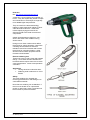
Heat Gun ...................................................175
Electric Soldering Iron..............................175
Portable Power Tool Safety ......................176
Care and Maintenance Portable Power Tools
..................................................................176
Hazards .....................................................177
Portable Power Tool Insulation.................177
Single Insulated (Class I) Equipment........177
Double Insulated (Class II) Equipment.....178
Legislative Requirements..........................178
Type of electrical equipment to be inspected
and tested includes: ...................................178
Construction Work....................................178
Section 3 – Verification and Testing.........179
T10 Sheet metal work encompassing:...........182
Sheet Metal Work Safety ..........................182
Sheet Metal Characteristics.......................183
Types of Sheet Material used in
Electrotechnology .....................................183
Electrotechnology Sheet Metal Tasks.......184
Sheet Metal Work Hand Tools..................185
Sheet Metal Work Power Tools ................189
Sheet Metal Work - Plan Activities ..........203
Safe Handling of Materials .......................203
Marking Out..............................................204
Cutting Sheet Metal ..................................206
Making a Lap Joint ...................................206
Folding Sheet Metal..................................208
Self-Secured Joints....................................212
Job Inspection ...........................................212
Clean up ....................................................212
Joining Lengths of Cable Duct..................213
Making a Turn Down................................214
Mitres or Angle Joints...............................216
Making Tee-Joints ....................................218
Drilling and Cutting Holes In Sheet Metal219
Sustainable Energy Work Practices ..........220
T11 Low tolerance measurement encompassing:
......................................................................222
Vernier Calliper (Vernier Gauge) .............222
Outside Micrometer ..................................228
Large Purpose Micrometers ......................231
Page 3 of 254
Digital Micrometers ................................. 232
Inside Micrometer .................................... 234
Depth Micrometer .................................... 235
Care of Micrometers................................. 236
T12 Dismantling and assembly techniques
encompassing: .............................................. 237
Dismantle and Assembly.......................... 237
Pliers......................................................... 237
Diagonal Cutting Pliers ............................ 238
Long Nose Pliers (Long Taper Nose)....... 238
Wire Strippers........................................... 239
Circlip Pliers............................................. 240
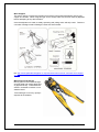
Crimping Tool .......................................... 241
Parallel Pin Punches ................................. 242
Feeler Gauge............................................. 242
Bearing Puller........................................... 243
Care and Maintenance of Hand Tools ...... 244
Disassembly Sequencing .......................... 246
Disassembly of an Electric Motor ............ 247
Reassembly of a Motor............................. 248
Importance of marking/labelling and storing
parts .......................................................... 249
Storing Parts during Disassembly............. 249
Machines with Close Fitting Parts............ 250
Temperature Variations ............................ 250
Gasket....................................................... 253
E102A Notes T2-T12 Version 4 (BG).doc
23 January 2014
Page 4 of 254
UEE11 ELECTROTECHNOLOGY TRAINING PACKAGE (Version 4)
UEENEEE102A Fabricate, assemble and dismantle utilities industry components
Modification History
Not Applicable
Unit Descriptor
Unit Descriptor 1)
1.1) Descriptor
This unit covers basic fitting and fabrication techniques as they apply in the various
utilities industry work functions. It encompasses the safe use of hand, fixed and
portable power tools; cutting, shaping joining and fixing using metallic and non-metallic
materials; dismantling and assembling equipment; basic mechanical measurement and
marking-out and reading drawings/diagrams.
Application of the Unit
Not Applicable
Licensing/Regulatory Information 1.2)
License to practice
During Training: Competency development activities are subject to regulations directly
related to licencing, occupational health and safety and where applicable contracts of
training such as apprenticeships.
In the workplace: The application of the skills and knowledge described in this unit
require a license to practice in the workplace where work is carried out on electrical
equipment or installations which are designed to operate at voltages greater than 50 V
a.c. or 120 V d.c.
Other conditions may apply under State and Territory legislative and regulatory
requirements.
Pre-Requisites
Prerequisite Unit(s) 2)
2.1) Competencies
Granting competency in this unit shall be made only after competency in the following
unit(s) has/have been confirmed.
UEENEEE101A Apply Occupational Health and Safety regulations, codes and
practices in the workplace
2.2) Further Information:
For the full prerequisite chain details for this unit please refer to Table 2 in Volume 1,
Part 2
Employability Skills Information
Employability Skills
3)
This unit contains Employability Skills
The required outcomes described in this unit of competency contain applicable facets
of Employability Skills. The Employability Skills Summary of the qualification in which
this unit of competency is packaged will assist in identifying Employability Skill
requirements.
E102A Notes T2-T12 Version 4 (BG).doc
23 January 2014
Page 5 of 254
Application of the Unit 4)
4.1) General Application
This unit applies to persons entering work in utilities industry and may be used in
school-based vocational programs.
4.2) Importation
RTOs wishing to import this unit into any qualification under the flexibility provisions of
NQC Training Package Policy
Elements and Performance Criteria Pre-Content 6)
Elements describe the essential outcomes of a unit of competency
Performance criteria describe the required performance needed to demonstrate
achievement of the Element. Assessment of performance is to be consistent with the
evidence guide.
Elements and Performance Criteria
1 Prepare for dismantling, assembling and fabrication work.
1.1 OHS procedures for a given work area are obtained and understood through
established routines and procedures.
1.2 Established OHS risk control measures and procedures in preparation for the work
are followed.
1.3 Safety hazard not previously identified are reported and advice on risk control
measures is sought from the work supervisor.
1.4 The nature of the work is obtained from documentation and from work supervisor to
establish the scope of work to be undertaken.
1.5 Advice is sought from the work supervisor to ensure the work is coordinated
effectively with others.
1.6 Materials required for the work are obtained in accordance with established
routines and procedures.
1.7 Tools, equipment and measuring devices needed to carry out the work are
obtained and checked for correct operation and safety.
1.8 Cutting tools such as drills and chisels are sharpened to suit the material on which
they are to be used.
2 Dismantle and assemble utilities industry apparatus.
2.1 Established OHS risk control measures and procedures for carrying out the work
are followed.
2.2 Circuits/machines/plant are checked as being isolated where necessary in strict
accordance OHS requirements and procedures.
2.3 Appropriate tools are selected and used correctly and
2.4 Manufacturer apparatus dismantling and assembling guides are used where
applicable.
2.5 Components are marked or tagged during the dismantling to help ensure correct
and efficient reassembly.
2.6 Dismantled components and parts are stored to protect them against loss or
damage.
2.7 Apparatus is dismantled and assembled efficiently without waste of materials and
energy and/or damage to apparatus and the surrounding environment or services.
2.8 Procedures for referring non-routine events to immediate supervisor for directions
are followed.
2.9 Routine quality checks are carried out in accordance with work instructions.
2.10 OHS risk control work completion measures and procedures are followed.
E102A Notes T2-T12 Version 4 (BG).doc
23 January 2014
Page 6 of 254
2.11 Work site is cleaned and made safe in accordance with established procedures.
2.12 Work supervisor is notified of the completion of the work in accordance with
established procedures.
3 Fabricate utilities industry components.
3.1 Established OHS risk control measures and procedures for carrying out the work
are followed.
3.2 Circuits/machines/plant are checked as being isolated where necessary in strict
accordance OHS requirements and procedures.
3.3 Appropriate tools are selected and used correctly and safely in fabricating
components.
3.4 Drawings and instruction for the fabrication of components are followed.
3.5 Component dimensions are determined directly or by calculation from information
given in job drawings and instructions.
3.6 Components are fabricated efficiently without waste of materials and energy and/or
damage to the surrounding environment or services.
3.7 Procedures for referring non-routine events to immediate supervisor for directions
are followed.
3.8 Routine quality checks are carried out in accordance with work instructions.
3.9 OHS risk control work completion measures and procedures are followed.
3.10 Work site is cleaned and made safe in accordance with established procedures.
3.11 Work supervisor is notified of the completion of the work in accordance with
established procedures.
Required Skills and Knowledge
REQUIRED SKILLS AND KNOWLEDGE 7)
This describes the essential skills and knowledge and their level, required for this unit.
Evidence shall show that knowledge has been acquired of safe working practices and
fabricating, dismantling, assembling of utilities industry components.
The knowledge and skills shall be contextualised to current industry standards,
technologies and practices.
KS01-EE102A Hand and power tools and their application
Evidence shall show an understanding of hand and power tools and their application to
an extent indicated by the following aspects:
T1 Mechanical drawing interpretation and sketching encompassing:
¾ drawing standards and conventions used in drawings of mechanical
components as specified in AS1100
¾ basic abbreviations and symbols used in drawing of mechanical components
¾ interpretation of mechanical drawings commonly used in the electrotechnology
industry (orthogonal projection, third angle - detail and assembly drawings,
pictorial views)
¾ laying out a drawing of mechanical components using engineering drawing
convention.
¾ freehand drawings of mechanical components showing all information needed
for its manufacture/fabrication
T2 Workshop planning and materials encompassing:
¾ methods used to work safely in an industrial work environment.
¾ typical non-electrical hazards in the workplace
¾ control measures for dealing with hazards identified.
E102A Notes T2-T12 Version 4 (BG).doc
23 January 2014
Page 7 of 254
¾ Conducting a risk assessment on a given work environment, documenting and
assessing the risks identified
¾ type of metallic and non-metallic materials used in the electrotechnology
industry and application of the common materials
¾ planning process
T3 Measuring and marking out encompassing:
¾ reasons for measuring and marking out
¾ tools used for marking out
¾ measuring and marking out a project accurately following correct procedures.
¾ sustainable energy work practices related to reducing waste when marking out.
T4 Holding and cutting encompassing:
¾ common tools for holding (bench vices, multi-grips, vice grips, wrenches).
¾ common tools for cutting metallic and non-metallic material (hacksaws, wood
saws, chisels, pliers, files)
¾ procedure for using a range of tools for cutting, shaping, and finishing metallic
and non-metallic materials
¾ safety procedures when using holding and cutting tools
T5 Drills and drilling encompassing:
¾ types of drills used in the electrotechnology industry
¾ sharpening twist drills
¾ drilling metallic and non-metallic components
¾ safe use of a bench drill
T6 Tapping and threading encompassing:
¾ type and size of commonly used threads used in electrotechnology work
¾ taps and tap wrenches
¾ tapping metallic and non-metallic components
¾ stock and die tools
¾ threading metallic and non-metallic components
T7 General Hand Tools encompassing:
¾ hammers used in electrotechnology work
¾ screwdrivers used in electrotechnology work
¾ spanners and sockets used in electrotechnology work
¾ pliers used in electrotechnology work
¾ assembling components applicable to electrotechnology industry using a variety
of hand tools.
T8 Joining techniques encompassing:
¾ types of machine screws and nuts
¾ forms of welding (Oxy-acetylene, electric arc welding).
¾ forms of brazing and hard soldering
¾ process of soft soldering
¾ joining components using machine screws
¾ joining components using welding, brazing or soldering techniques
T9 Portable electric power tools encompassing:
¾ portable electric power tools (grinders, drills, jigsaws, saws)
¾ applications of portable electric power tools used in the electrotechnology work.
¾ using portable power tools.
E102A Notes T2-T12 Version 4 (BG).doc
23 January 2014
Page 8 of 254
¾ fabricating components using power tools (drills, grinders)
T10 Sheet metal work encompassing:
¾ types of sheet metal materials used in the electrotechnology work.
¾ names and applications of the types of fabrication materials.
¾ tools used with sheet metals in electrotechnology work (hacksaw, tinsnips,
guillotines, punches, notching tools, folding machines)
¾ techniques used in fabricating sheet metal (cutting, bending, drilling/punching,
joining, cutting mitres).
¾ marking out, cutting, bending, drilling and/or cutting and/or punching holes,
joining and cutting mitred joints using sheet metal.
¾ sustainable energy work practices to reducing waste when fabricating using
sheet metal.
¾ fabricating components using sheet metal and fabrication tools.
T11 Low tolerance measurement encompassing:
¾ tolerance
¾ techniques in using vernier callipers
¾ techniques in using micrometers.
¾ using vernier callipers to measure engineering components
¾ using micrometers to measuring engineering components
T12 Dismantling and assembly techniques encompassing:
¾ tools used in dismantling and assembling electrotechnology equipment
(spanners, screwdrivers, bearing pullers, etc).
¾ procedures for ensuring the safe treatment of dismantled components.
¾ dismantling electrical, electronic, instrumentation or refrigeration/air conditioning
piece of equipment using correct procedures.
¾ assembling electrical, electronic, instrumentation or refrigeration/air conditioning
piece of equipment using correct procedures.
EVIDENCE GUIDE 9)
The evidence guide provides advice on assessment and must be read in conjunction
with the Performance Criteria, Required Skills and Knowledge, the Range Statement
and the Assessment Guidelines for this Training Package.
The Evidence Guide forms an integral part of this unit. It must be used in conjunction
with all parts of the unit and performed in accordance with the Assessment Guidelines
of this Training Package.
Overview of Assessment 9.1)
Longitudinal competency development approaches to assessment, such as Profiling,
require data to be reliably gathered in a form that can be consistently interpreted over
time. This approach is best utilised in Apprenticeship programs and reduces
assessment intervention. It is the industry-preferred model for apprenticeships.
However, where summative (or final) assessment is used it is to include the application
of the competency in the normal work environment or, at a minimum, the application of
the competency in a realistically simulated work environment. It is recognised that, in
some circumstances, assessment in part or full can occur outside the workplace.
However, it must be in accordance with industry and regulatory policy.
Methods chosen for a particular assessment will be influenced by various factors.
These include the extent of the assessment, the most effective locations for the
E102A Notes T2-T12 Version 4 (BG).doc
23 January 2014
Page 9 of 254
assessment activities to take place, access to physical resources, additional safety
measures that may be required and the critical nature of the competencies being
assessed.
The critical safety nature of working with electricity, electrical equipment, gas or any
other hazardous substance/material carries risk in deeming a person competent.
Sources of evidence need to be 'rich' in nature to minimise error in judgment.
Activities associated with normal everyday work have a bearing on the decision as to
how much and how detailed the data gathered will contribute to its 'richness'. Some
skills are more critical to safety and operational requirements while the same skills may
be more or less frequently practised. These points are raised for the assessors to
consider when choosing an assessment method and developing assessment
instruments. Sample assessment instruments are included for Assessors in the
Assessment Guidelines of this Training Package.
Critical aspects of evidence required to demonstrate competency in this unit 9.2)
Before the critical aspects of evidence are considered all prerequisites must be met.
Evidence for competence in this unit shall be considered holistically. Each element and
associated performance criteria shall be demonstrated on at least two occasions in
accordance with the 'Assessment Guidelines - UEE07'.
Evidence shall also comprise:
¾ A representative body of work performance demonstrated within the timeframes
typically expected of the discipline, work function and industrial environment. In
particular this shall incorporate evidence that shows a candidate is able to:
o Implement Occupational Health and Safety workplace procedures and
practices, including the use of risk control measures as specified in the
performance criteria and range statement
o Apply sustainable energy principles and practices as specified in the
performance criteria and range statement
o Demonstrate an understanding of the essential knowledge and
associated skills as described in this unit. It may be required by some
jurisdictions that RTOs provide a percentile graded result for the
purpose of regulatory or licensing requirements.
o Demonstrate an appropriate level of skills enabling employment
o Conduct work observing the relevant Anti Discrimination legislation,
regulations, polices and workplace procedures
¾ Demonstrated consistent performance across a representative range of
contexts from the prescribed items below:
o Fabricate, dismantle, assemble of utilities industry components as
described in 8) and including:
A Selecting and using hand tools appropriate to a task correctly and
safely
B Selecting and using power tools appropriate to a task correctly and
safely
C Sharpening at least two drill bits each for use different types of
material.
D Interpreting mechanical drawings/diagrams and instructions
correctly.
E Dismantle and assemble an apparatus relevant to utilities industry
discipline in which competency is sought.
E102A Notes T2-T12 Version 4 (BG).doc
23 January 2014
Page 10 of 254
F Fabricate a component relevant to the utilities industry discipline in
which competency is sought.
G Dealing with unplanned events
Context of and specific resources for assessment 9.3)
This unit should be assessed as it relates to normal work practice using procedures,
information and resources typical of a workplace. This should include:
¾ OHS policy and work procedures and instructions.
¾ Suitable work environment, facilities, equipment and materials to undertake
actual work as prescribed in this unit.
These should be used in the formal learning/assessment environment.
Note: Where simulation is considered a suitable strategy for assessment, conditions
for assessment must be authentic and as far as possible reproduce and replicate the
workplace and be consistent with the approved industry simulation policy.
The resources used for assessment should reflect current industry practices in relation
to dismantling, assembling and fabricating utilities industry components.
Method of assessment 9.4)
This unit shall be assessed by methods given in Volume 1, Part 3 'Assessment
Guidelines'.
Note: Competent performance with inherent safe working practices is expected in the
Industry to which this unit applies. This requires that the specified essential knowledge
and associated skills are assessed in a structured environment which is primarily
intended for learning/assessment and incorporates all necessary equipment and
facilities for learners to develop and demonstrate the essential knowledge and skills
described in this unit.
Concurrent assessment and relationship with other units 9.5)
For optimisation of training and assessment effort, competency development in this unit
may be arranged concurrently with unit:
Range Statement
RANGE STATEMENT 8)
This relates to the unit as a whole providing the range of contexts and conditions to
which the performance criteria apply. It allows for different work environments and
situations that will affect performance.
This unit shall be demonstrated in relation to installation, fault finding, maintenance,
repair or development work functions in any of the following disciplines:
¾
¾
¾
¾
Electrotechnology Disciplines
Gas industry Disciplines
ESI Transmission, Distribution and Rail Disciplines
ESI Generation Disciplines
Generic terms used throughout this Vocational Standard shall be regarded as part of
the Range Statement in which competency is demonstrated. The definition of these
and other terms that apply are given in Volume 2, Part 2.1.
E102A Notes T2-T12 Version 4 (BG).doc
23 January 2014
Page 11 of 254
Unit Sector(s)
Not Applicable
Competency Field 2.3)
Literacy and numeracy skills
Participants are best equipped to achieve competency in this unit if they have reading,
writing and numeracy skills indicated by the following scales. Description of each scale
is given in Volume 2, Part 3 'Literacy and Numeracy'
Reading 3 Writing 3 Numeracy 3
2.3) Literacy and numeracy skills
Competency Field 5)
Utilities industry
E102A Notes T2-T12 Version 4 (BG).doc
23 January 2014
Page 12 of 254
Introduction
Tools are designed to make a job easier and enable you to work more efficiently and safely.
Without the proper tools and the knowledge of how to use them, a tradesperson wastes time,
reduces efficiency and may even cause themselves an injury.
The aim of this note is to explain the function, the correct and safe use and proper care of the
tools you will use while working in the electrotechnology industry.
T2 Workshop planning and materials encompassing:
¾
¾
¾
¾
¾
¾
Methods Used To Work Safely In An Industrial Work Environment.
Typical Non-Electrical Hazards In The Workplace
Control Measures For Dealing With Hazards Identified.
Conducting A Risk Assessment On A Given Work Environment, Documenting And
Assessing The Risks Identified
Type Of Metallic And Non-Metallic Materials Used In The Electrotechnology Industry
And Application Of The Common Materials
Planning Process
Safety
The Workplace Health and Safety (WHS) Act 2011 requires the PCBU (Person conducting a
business or undertaking) to ensure the health and safety of workers, so far as is “reasonably
practicable”. In addition, while at work, workers are required to take reasonable care for their
own health and safety and that of others who may be affected by their actions or omissions.
They must also cooperate with any reasonable instruction given by the PCBU and any
reasonable policy or procedure of the PCBU to comply with the WHS Act 2011 and WHS
Regulation 2011. This means that you have a responsibility to ensure that any decisions or
actions on your part do not put yourself or others at risk. This means:
•
•
•
Avoid unsafe practices,
Follow your supervisor’s instructions,
Use correct methods.
Workplace injuries can be caused by many factors including:
• Poor design of factories, equipment and work areas.
• Poor management and organisational practice.
• Lack of instruction provided on safe use of equipment.
• Failing to provide or failure to use personal protective equipment (PPE).
• Using tools and equipment incorrectly.
• Distracting others from their work.
• Individual unsafe practices such as fooling around in workshop areas.
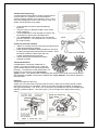
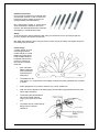
Hazards in the Workplace
“Hazard” is a term used to describe something that has the potential to cause harm, and a
“risk” is a measure of the possibility of a specific harmful effect in given circumstances. It is
important to know the difference between these two terms. Types of workplace hazards
include:
Electrical: Exposure to electrical energy from, direct contact with exposed conductors or
indirect contact with a faulty piece if equipment,
Gravity: Falls, trips and slips of a person, struck by falling objects,
Kinetic energy: Hitting objects with a part of the body or being hit by moving objects,
Radiation (ionising and non-ionising): Exposure to ultraviolet (UV) radiation, arc flashes,
infrared radiation, microwaves and lasers etc
Vibration: Exposure to whole of body vibration or vibration to parts of the body only, such as
hands,
E102A Notes T2-T12 Version 4 (BG).doc
23 January 2014
Page 13 of 254
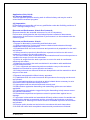
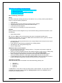
Noise: Exposure to single, sudden sound
or long term exposure to sound.
Chemical: Exposure to products such as
solvents, glues, cleaning agents,
thinners, etc.
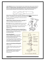
Body stressing: Muscular stress while
lifting, carrying or putting down objects,
muscular stress while handling objects
other than lifting, carrying or putting down
or muscular stress with no objects being
handled, repetitive movement, low
muscle loading,
Ergonomics: Fatigue or workplace
design causing stress, causing errors,
Substances: Single contact with
chemical or substance or long-termcontact with chemicals or substances,
reptile, insect or spider bites and stings,
other unspecified contact with chemical
or substance, fire and explosion,
Airborne: Exposure to dusts eg. wood,
asbestos, silica, gases eg. carbon
monoxide, fumes eg. metal fume,
vapours eg. Solvents, mists eg. acids,
solvents
Skin contact: (absorption) Contact with
eg. Pesticides, corrosive substances eg.
acid, alkali, solvents; photosensitisation
eg. Creosote; affected skin exposed to
sunlight; allergic eg. nickel, epoxy,
Biological (microbial) substances: Exposure to
bacterial, fungal, viral, parasitic
Mechanical: Refers to being caught between, struck by
or against, mobile or fixed plant, and vehicles, powered
equipment, tools and appliances, non-powered hand
tools, appliances and equipment.
Psychological hazards: Those situations that cause
stress to a worker. This kind of hazard troubles an
individual to an extent that their general well-being is
affected.
Identifying Workplace Hazards
• Study workplace injury and illness records,
• Stay current on WHS trends,
• Analyse all new work procedures for WHS,
• Investigate all workplace incidents and near
misses,
• Conduct regular safety audits and inspections,
• Improve consultation and feedback procedures.
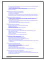
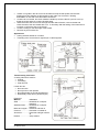
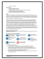
Hazard Control Measures to Reduce Risk
There are “five” categories of control measures:
E102A Notes T2-T12 Version 4 (BG).doc
23 January 2014
Page 14 of 254
“elimination”, “substitution”, “engineering controls”,
“administrative controls” and “personal protective
equipment”.
1. Elimination of the hazard is the most effective
means of hazard control as it involves the physical
removal of the hazard. Eg: If employees are
required to work high above the ground, the hazard
can be eliminated by moving the piece they are
working on to "ground level" to eliminate the need to
work at heights.
2. Substitution involves removing something that
produces a hazard (similar to elimination) but
replacing it with something that does not produce a
hazard. An example of substitution is replacing an
existing chemical cleaner with a less toxic type.
3. Engineering controls do not eliminate hazards, but
rather keep people isolated from hazards.
Examples are better guards on machines etc.
4. Administrative controls are changes to the way
people work. Examples of administrative controls
include procedure changes, employee training, and
installation of signs and warning labels.
Administrative controls do not remove hazards,
rather limit or prevent people's exposure to the
hazards. Eg: Completing a task out-of-hours when
all electrical power can be isolated.
5. Personal Protective Equipment (PPE) is the least
effective way to control hazards. PPE is the method
of last resort because of the high potential for the
PPE to become ineffective due to damage or aging
etc.
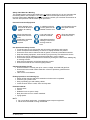
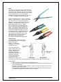
Wear Appropriate PPE (Personal; Protective
Equipment)
It is essential to safety that you always wear the
appropriate personal protective equipment assigned to
the task you are performing. This may include some of
the following items:
•
•
•
•
•
•
•
•
Suitable clothing
Safety shoes or boots,
Safety glasses,
Goggles,
Hair net or cap,
Hearing protection,
Gloves,
Breathing apparatus.
Clothing
Suitable clothing should always be worn in the
workshop. Loose sleeves and other loose clothing
can easily catch on parts of a vehicle or tangle in
E102A Notes T2-T12 Version 4 (BG).doc
23 January 2014
Page 15 of 254
workshop equipment. Rotating parts, such as fans, belts and drills, are particularly dangerous
as these could catch a loose sleeve and quickly pull a hand into a moving part. Long hair that is
not under control can become tangled in rotating parts. This can cause severe personal injury.
Always tie back long hair or wear a cap or other headgear such as a hair net.
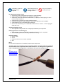
NB: An example of an unsafe work practice is an operator with “long hair” using rotating
machinery without using some form of a hair protector.
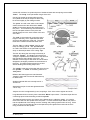
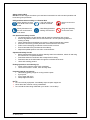
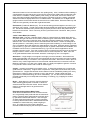
Footwear
Boots and shoes should be of stout safety design.
Safety footwear is designed with reinforced toecaps to
provide some level of protection against some falling
objects.
Safety glasses and
shields
Eyes need special
protection. Clear safety
glasses should be worn
when using a grinding
wheel, or for any
workshop job where dust
or metal particles are
prevalent.
Manual Handling
Manual tasks can contribute to injuries affecting all
parts of the body, particularly the back, shoulder and
wrist. These are commonly called musculoskeletal
disorders. Extra care is needed when performing
manual tasks. If the task is beyond your capabilities,
then either:
•
•
•
Seek help,
Use a mechanical lifting aid, (eg: bar)
Use a mechanical lifting device (eg:
Crane.)
Over time, damage can build up in your body through
things such as:
•
•
•
•
•
Handling loads - frequent lifting with the back
bent and/or twisted, or pushing or pulling
loads
Repetitive work - using the hand or arm, or
gripping tools or loads tightly
Static work of the whole body - working in a
fixed position with the back bent, continuous
sitting or standing, or driving vehicles for long
periods
Static work of the upper limb - working with
the neck, shoulders and arms in a fixed
position (such as using tools and handling
heavy loads)
Vibration – using tools or coming into contact
with vibrating surfaces while undertaking manual tasks (such as sitting on a large
machine).
E102A Notes T2-T12 Version 4 (BG).doc
23 January 2014
Page 16 of 254
Safety and tools
Small hand tools should be kept clean and tidy. Always return hand tools back to their storage
area when they are no longer required. They should be used correctly and maintained in good
condition. Larger tools should be kept under control and not scattered about. Keep equipment
out of aisles and working spaces where they would become a hazard.
Use of machines
Before using any machine, know how it works. Always check the SOP (Standard Operating
Procedure) for the machine which should be clearly displayed beside the machine.
It is important to carry out checks and minor maintenance before a machine is used so that it
always remains in a serviceable condition. Always keep your hands away from moving parts.
When using a machine tool, NEVER attempt to “feel” the finished surface with the machine still
in operation. Machines should be completely stopped before any checks or measurements are
made.
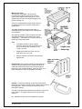
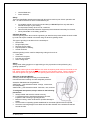
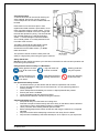
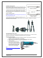
Machine guards
Guards should be fitted to machines that have external moving parts. If the guard is missing
from a machine, then it MUST NOT be used. The guards are there to protect the operator, who
should make sure that the guards are correctly in place. Eg: Grinders should have covers over
the grinding wheels to prevent grindings from being thrown towards the operator. The tool rests
should always be adjusted close to the edges of grinding wheels. This will prevent an article
that is being ground from jamming between the tool rest and the grinding wheel. This could
easily injure the operator, damage the wheel, or ruin the article being ground.
Work Area
A clean and tidy area is safer than an untidy work
area. Practice good housekeeping in your work area
by keeping the area clean, ordered and tidy.
Always immediately report any damaged, worn or
inoperative items or any unsafe conditions.
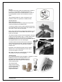
Care in the Use of Hand Tools
Hand tools can cause injuries when an incorrect,
improvised or defective tool is used. It is important to
observe and carry out the following points:
•
•
•
•
•
•
Make sure you select the correct type and
size of tool for the job,
Check the condition of any tool before you
use it,
Do not use tools that are worn
out or damaged,
Maintain tools in good condition
and remember that cutting tools
need to be sharp to be safe,
Make sure that you use each tool
in the correct manner,
Store and carry your tools safely.
E102A Notes T2-T12 Version 4 (BG).doc
23 January 2014
Page 17 of 254
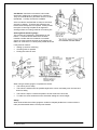
Risk Assessment
A risk assessment must be completed before commencing any practical task. Its purpose is to
discover the “realistic” risks to be managed and then prioritize the risks inherent in the task.
This usually involves walking around the intended work zone, imagining the task to be
performed and determining what could be reasonably expected to cause harm.
Then, based on the level of risk, put control measures in place to reduce the risk level. The risk
level is determined by the consequences if it does occur, and the probability that it will occur. A
safe work plan means listing all of the control measures needed to either eliminate the identified
hazards or at least, reduce the risk to an acceptable level.
Note:
Workshop and tool safety is such an important topic; some of the points discussed
above will be reinforced in each of the topic areas.
Materials Used In The Electrotechnology Industry
Materials used in the electrotechnology industry can be grouped under three main categories:
¾
¾
¾
Electrical conductors
Electrical insulators
Equipment construction and support
Electrical Conductors
Most conductors are metals because they have a relatively low resistance to current flow. While
“silver” and “gold” are the best conductors, their high cost makes them unsuitable for most
practical applications. Copper, aluminium and brass are the most commonly used materials
due to their good conductivity and cost. Copper and aluminium are used for both general circuit
conductors and for large capacity busbars. Brass is used for its hardness when is used for
neutral and earth links in switch boards.
Electrical Insulators
There are many insulating materials available that can be used as electrical insulators.
Electrical insulation is used in an electrical system to prevent unwanted flow of electric current
to the earth or between phases. An insulating material must be mechanically strong, have a
high dielectric strength to withstand the voltage stresses, high insulation resistance to prevent
leakage current to the earth and it must also be free from unwanted impurities.
The physical as well as electrical properties must be independent of temperature changes.
There are many materials in common use including PVC (Polyvinyl Chloride), Nylon, Porcelain,
Mica, Fibre glass, Perspex, Bakelite, Densified wood and Insulpanel (Phenolic resin
impregnated paper base laminated sheet) used in switchboard construction.
Each material is application specific.
Equipment Construction and Support
Materials used for construction and support are extremely varied. Materials include steel (mild
and stainless), aluminium, brass and copper are well as a full range of plastics etc.
Planning Process
Planning a job correctly involves coordinating all of the tasks from start to finish. Information
can be derived from plans and specifications, quality assurance requirements and occupational
health and safety requirements. This understanding enables problems to be avoided and also
helps:
¾ Increase workplace safety,
¾ Reduce damage to tools and equipment,
¾ Reduce costly mistakes,
¾ Avoid processes which do not comply with the job plans or specifications, Australian
Standards or codes of practice.
E102A Notes T2-T12 Version 4 (BG).doc
23 January 2014
Page 18 of 254
Planning:
¾ Helps ensure the safety of workers and equipment,
¾ Ensures that quality assurance requirements will be met,
¾ Ensures that the type of tools and equipment needed to complete the tasks are
identified and are available,
¾ Ensures that the types of personal protective equipment needed for safe working are
identified.
Task Scheduling
Time management and the amount of materials required for the job are key elements of the
planning process. The practical difficulties of estimating times are considerable. The important
point to consider is that the time allocated to each activity should be realistic rather than
desirable. In practice, the estimation of times for each activity for a small job or a large project
is derived from a person (or persons) with previous experience in performing or managing
similar tasks. Alternatively, the duration of particular activities may be extracted from records
concerning similar tasks carried out in the past.
Each individual task must be allocated an appropriate amount of time, suitable equipment and
materials required and a work method statement and risk analysis.
Safe Work Method Statement
Work method statements detail how each work related activity can be carried out safely. They
are required for all work related tasks - from the most basic task, such as using an electric drill
to a more difficult task, such as the use of a lathe. Besides the process they also detail the
Personal Protective Equipment (PPE) which will be required for each task. For example:
• safety helmets
• safety shoes
• safety glasses
• respirator
• gloves
• ear plugs / ear muffs
• wet weather gear
• sun protection
• fall arrest systems
• back braces etc
E102A Notes T2-T12 Version 4 (BG).doc
23 January 2014
Page 19 of 254
T3 Measuring and marking out encompassing:
¾
¾
¾
¾
reasons for measuring and marking out
tools used for marking out
measuring and marking out a project accurately following correct procedures.
sustainable energy work practices related to reducing waste when marking out.
Measurement
The system of measurement in use in Australia and in most countries of the world is the SI
(System International) Metric system. The “metre” is the standard unit for length, with subdivisions and multiples of the metre being based on the decimal system.
All engineering measurements, however, are made in millimetres, and all dimensions shown on
engineering drawings are given in millimetres. There are 1000 (103) millimetres in a metre. The
abbreviation for metres is the lower case “m” and the abbreviation for millimetres is lower case
“mm”.
Precision, Tolerance and Accuracy of Measurement
The “precision” of a measurement system, also called “reproducibility” is the degree to which
repeated measurements under unchanged conditions show the same results. In practical
terms, this equates to the minimum size “unit” being used to take a measurement. The smaller
the “unit” used, the more “precise” the final measurement.
eg: If we attempt to go beyond the base unit of measurement and attempt to estimate by using
just a part of the smallest graduation, then there is a high probability that the reading cannot be
repeated. Ie: We have taken a “guess”, which is “imprecise”.
An engineering “tolerance” is the “predefined” permissible limit(s) of variation in a physical
dimension etc. eg: The tolerance of a job may be given as, “±1mm” which means “1mm” more
or “1mm” less than the originally set value. It is the “client” or the nature of the task which
defines the tolerance to which you are to work. For example, if you are required to fit a bearing
to the shaft of an electric motor, then the tolerance may be stated as “±0.01mm.
The “accuracy” of measuring equipment defines its ability to take an exact reading. The degree
of closeness of the measurement to the quantity's actual (or true) value reflects the “accuracy” it
can achieve. The bigger the “difference”, the more “inaccurate” it is. The accuracy of
measuring equipment is determined by the “smallest unit” available to it. Eg: The accuracy of
a standard engineering ruler is “0.5mm” or “0.1mm”; a vernier “0.02mm” and a “micrometer
“0.01mm”.
Measuring Tools
The process of measuring is one of aligning an unknown physical quantity, the “work piece”,
against a known “standard”, (ie: the measuring tool), and gauging the size.
The graduated measuring instruments typically used by a tradesperson are a tape and steel rule
and depth gauges. High precision measuring tools such a vernier and micrometer are covered
in a later topic.
Care of Measuring Equipment
Measuring tools are precision instruments and are easily damaged. They should be stored in
locations or containers where they will be protected from corrosion, dirt contact and also from
harmful contact with heavier tools, such as hammers, chisels and files.
The best way to ensure they are not damaged is to return them to their protective cases when
they are not in use. Also, never leave the jaws of the instrument firmly closed as they will
stretch and loose accuracy. They should always be stored with the jaws slightly apart to allow
for physical changes due to temperature variations. While the equipment is in use, you should
always guard against:
E102A Notes T2-T12 Version 4 (BG).doc
23 January 2014
Page 20 of 254
•
•
•
•
Dropping the instrument.
Dropping other equipment onto the measuring instrument.
Allowing it to come into contact with filings, grinding grit or dirt.
Taking measurements whilst the machinery is still running.
To protect instruments from corrosion, they should be cleaned and lightly coated with suitable
oil at the completion of the day’s work. At regular intervals these instruments should be
dismantled, cleaned, checked and if necessary
re-calibrated.
If contact surfaces are scored or burred; if
spindles are bent, or if the frames are strained,
then the accuracy of the instrument can be
compromised and the continued use of the tool
will result in faulty work.
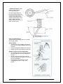
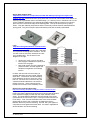
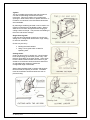
Tape Rule or Tape Measure
A measuring tape consists of a flexible blade of
steel housed in a metal or plastic case.
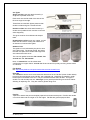
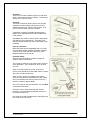
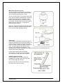
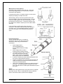
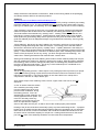
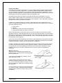
Long Tape
This instrument is used to measure very long
lengths, typically up to30m but longer designs up
to 50m are available. An application could be
measuring the route length for
a conduit or cable duct run.
The “flexible” tape may be
made of either nylon coated
steel or fibre glass. The measuring tape is returned into the case by operating a turning
mechanism with a handle as shown to the right. On some
designs the handle can be folded away when not in use. An
example is shown to the right.
Ref: http://www.surveyequipment.com
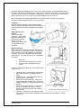
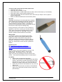
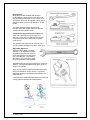
Steel Tape
This tape is used to measure shorter lengths up to about 8 to 10
metre lengths.
Tape rules have a power return spring which automatically
returns the tape blade into the housing. Do not
allow the tape to return in an uncontrolled fashion
as the tip hook will break off. A lock button is
usually included to secure the blade in the open
position as well as slow its return into the case.
Danger
Because steel is an excellent conductor of
electricity, NEVER use a “steel tape” in close
proximity to live electrical terminals.
Tape Maintenance
Correctly maintained steel tapes and tape rules will
last for many years. Follow these steps:
•
Keep the blade free from grit and moisture.
E102A Notes T2-T12 Version 4 (BG).doc
23 January 2014
Page 21 of 254
•
•
Slide the blade between a slightly oiled rag when returning it into the case.
Avoid leaving the blade exposed to the direct rays of the sun as this can buckle it.
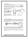
Using Tapes
Tapes can be graduated in either all metric or a combination of metric and imperial (feet and
inches) measurements.
A steel tape can be used in most situations, but it is best used for on-site setting out and for
taking on-site measurements.
The fixed end hook on a steel tape can move to compensate for the thickness of the metal
when taking inside or outside measurements, so it is important to place it correctly in position.
The tape rule is used for all types of measuring and setting out tasks within its length. Its
flexibility enables it to be used for measuring around curved surfaces.
E102A Notes T2-T12 Version 4 (BG).doc
23 January 2014
Page 22 of 254
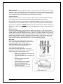
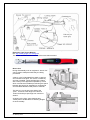
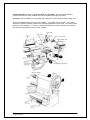
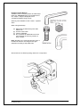
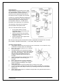
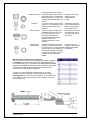
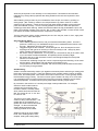
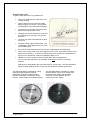
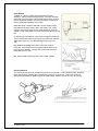
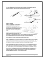
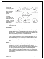
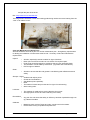
Distance Measuring Wheel
Ref: http://www.laserlevel-tripod.com
A distance measuring wheel, (also called a
surveyor’s wheel) is an excellent tool for
measuring longer distances with reasonable
accuracy. They are ideal when measuring the
route length of underground cable or aerial
cable runs such as when estimating costs or
cable quantities etc.
Each revolution of the wheel measures a
specific distance, such as a “metre” and as the
revolutions are automatically counted with a
device attached to the wheel it measures the total distance directly.
The design will provide reasonable accuracy on a smooth surface, such as pavement, but on
rough terrain, wheel slippage and bouncing can reduce the accuracy somewhat. Soft sandy or
muddy soil can also affect the rolling of the wheel. As well, obstacles in the way of the path may
have to be accounted for separately. When using keep track of any circumstance on the path
that can influence the accuracy of the distance measured and either measure that portion with
an alternative technique, such as a measuring tape, or make a reasonable estimate of the
correction to apply.
To use the device, first reset the counter and locate the wheel at the point you want to start
measuring, and roll in a straight direction to the stopping point, then read distance travelled
directly off the counter.
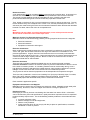
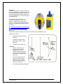
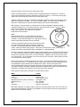
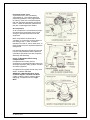
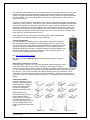
Laser Range Meters
Ref: www.ehud-engel.co
A laser distance meter uses a laser beam to
determine the distance from a fixed starting point
to another object. The distance is measured
along a laser beam emitted by the tool to the
point at which the beam strikes a reflective
surface. The target from which the measurement
is taken is clearly identified by the red laser
measuring spot. The range of the tool depends
on the reflectance and structure of the target surface from which measurements are taken.
Measurements taken through glass or from plastic foam materials such as polystyrene foam or
from highly reflective surfaces (mirrors, glass, etc.) may produce inaccurate results.
The most common form of laser meter operates on the “time-of-flight” principle by sending a
laser pulse in a narrow beam towards the object and measuring the time taken by the pulse to
be reflected off the target and returned to the sender. This measuring principle permits highly
accurate and reliable measurement of distances to objects without need for special reflectors.
The specifications for these devices vary between manufacturers, but the Hilti PD42 (as shown
above) will measure from 0.05m to 200m with an accuracy of ± 1mm.
Laser Safety: Depending on the model purchased, generally these tools comply with Laser
Class 2 in accordance with IEC825 -1:2003 / EN60825-1:2003 and may be used without need
for further protective measures. The eyelid closure reflex protects the eyes when a person
looks into the beam unintentionally for a brief moment. Nevertheless, as with the sun, one
should not look directly into sources of bright light and NEVER direct the laser beam toward
persons.
E102A Notes T2-T12 Version 4 (BG).doc
23 January 2014
Page 23 of 254
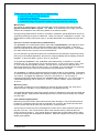
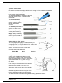
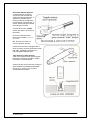
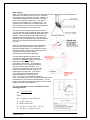
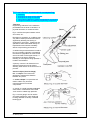
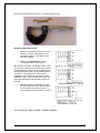
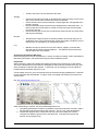
Steel Rule
(Engineer’s Rule)
Steel rules are designed to accurately measure lengths in the range between 0 to 300mm to
2000mm. For lengths longer than 2m, then a steel tape is used. An example of a steel rule is
shown below:
The ends and edges of the rule form important reference points, as it is from these surfaces that
accurate measurements are to be taken. If the rule were to be used as a scraper, a
screwdriver, a lever or as a piece of packing, then the resultant damage would make it
unreliable as a reference tool for future accurate measuring.
“Errors” in measurement can occur from any or a
combination of the following:
•
•
•
•
•
Wear on the end of the rule,
Graduation errors in the manufacture
of the rule,
Poor light conditions,
Rule not held parallel or at right
angles to the work piece,
“Parallax error” which is a
displacement or difference in the
apparent, position of an object when
viewed along two different lines of
sight.
An engineer’s rule is graduated in 1mm increments
on one side and 0.5 mm increments on the other.
This means its accuracy is “0.5mm”.
To achieve reading accuracy and “reduce
“parallax error” when reading this tool, always
align the eye carefully with the point or edge of the
work piece where the measurement is being taken,
and then look closely at the rule graduations.
Positioning the Rule
• Correct use of steel rules is necessary for accurate reading. Proceed as follows: • Place yourself and the article to be measured in the best reading light.
• Position the rule at right angles to your line of sight.
• Make certain the rule that you use has fine clear graduations cut right to the edge.
E102A Notes T2-T12 Version 4 (BG).doc
23 January 2014
Page 24 of 254
Edge of Rule Method
If the steel rule is worn on the end
then the following method is
suggested.
•
•
•
•
•
•
Steady the work with your left
hand.
Hold the rule with your right
hand and steady it with your
right thumb against the work.
Place the end of the rule on
the surface so that the face of
the rule is at right angles to
the work.
Place the edge of the rule on
the surface so that the face of
the rule is at right angles to
the work and square across
it.
Sight up the first numbered
graduation with the left hand
edge of the work.
Sight up the nearest
graduation in line with the
right hand edge of the work
and take the reading.
NB: Remember to subtract the first
number graduation from your final
reading to obtain the accurate
measurement required.
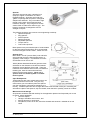
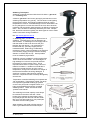
Other Uses for the Steel Rule
A steel rule can also be used as a:
•
•
•
Guide to draw or scribe a
straight line
Straight edge to test the
accuracy of a flat surface
Scale for setting dividers and
other marking out tools
Ref:
http://www.tractorsupply.com
E102A Notes T2-T12 Version 4 (BG).doc
23 January 2014
Page 25 of 254
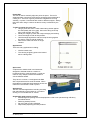
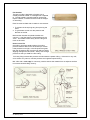
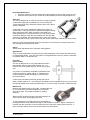
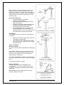
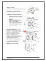
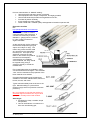
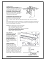
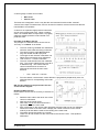
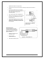
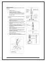
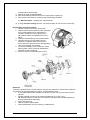
Rule Depth Gauge
A depth gauge is a measuring tool developed
from a steel rule. Depth gauges are used to
measure:
•
•
•
Depths of holes
Depths of recesses and slots
Distances in from the edges of work
The depth gauge consists of a narrow
graduated steel rule, fitted with a sliding frame
that may be clamped along the rule.
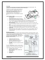
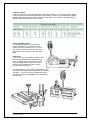
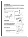
Using a Depth Gauge
Use a depth gauge to measure the depth of a
recess as follows: •
•
•
•
•
•
•
•
Hold the frame of the depth gauge
between the thumb and finger of one
hand.
Loosen the locking screw with the
thumb and first finger of your other
hand.
Hold the frame base firmly down on the
surface across the recess of the work to
be measured.
Hold the gauge square to the work by
steadying the rule with the first finger of
one hand.
Use the first finger of your other hand to
press the sliding rule down until you feel
the lower end touch against the bottom
of the recess.
Tighten the locking screw.
Lift the gauge carefully out of the recess
and away from the work.
Turn the gauge into a position where you
can read the depth of the recess directly
from the rule scale.
E102A Notes T2-T12 Version 4 (BG).doc
23 January 2014
Page 26 of 254
Marking Out Tools
Marking out is the preliminary work needed to establish the guide lines and centre marks
required for cutting, drilling and machining. It is necessary to ensure that the finished job
precisely meets the job specifications. For “manual tasks” an engineering drawing is typically
provided which contains the details necessary for the tasks to follow.
For “automatic tasks”, the marking-out is first created as a drawing using Computer Aided
Drawing (CAD) software and the custom designed “program” is then used to direct appropriate
machines to perform the engineering tasks to follow.
Marking Out Procedure
Marking out or lining is the process of placing accurate lines on metal surfaces in order to
establish limits for the work. Ie: File, cut and drill etc. Marking out also establishes definitively if
the work piece will accommodate the intended task.
Inspection of the Work Prior to Marking Out
Begin by checking:
•
•
•
The physical size of the raw stock material to be certain that it will accommodate the
finished size following all of the machining and filing that you will need to perform,
The stock material itself for signs of cracks, flaws, surface defects, warps and twists etc,
That this stock is the correct material for the job.
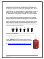
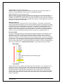
Marking Medium
To ensure scribed lines show up clearly on the work piece, the relevant area of the work should
be pre-coated with a suitably coloured marking-off medium. Commonly used marking mediums
include:
•
Chalk
•
Whitewash
•
Copper sulphate solution
•
Spirit-based metal marking dye
•
White water-based acrylic paint
The marking-off medium selected should contrast in colour with the colour of the working
surface.
•
Chalk is ideal for small areas on rough surfaces of castings
•
White water-based acrylic paint would be more effective on larger areas of rough
surfaces of castings etc.
•
Bright steel or machined steel is best suited to spirit-based marking dye. An
alternative to the marking dye is copper sulphate solution.
•
A dark permanent felt marking pen is also acceptable.
A thin coating is more preferable than a thick coat. Lines will show up sharp and clean with a
thin coat.
NB: For a small piece of stock material, it is easier to coat the entire job. For a large object,
strategically coat only those areas that are to be worked on.
E102A Notes T2-T12 Version 4 (BG).doc
23 January 2014
Page 27 of 254
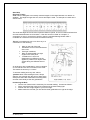
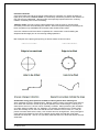
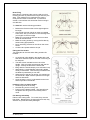
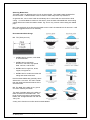
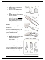
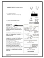
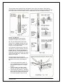
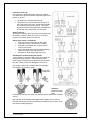
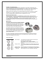
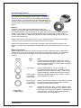
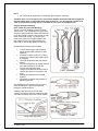
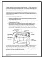
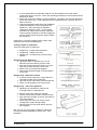
Types of Marking-out Lines
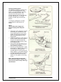
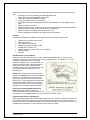
Datum Lines
The word "datum" is used to indicate a valid starting point such as line(s), edge(s) or surface(s).
A “datum edge” is a straight edge running the length of the material. It provides the starting or
reference position to begin marking out. The marking out for a job can originate from one or
more datum points, lines or surfaces. The datum may be a manufactured edge of the stock
material or if the existing edges on the material are too rough, the datum may be scribed line(s)
that are drawn near the edges. In some situations, the datum point may two intersecting lines
established to locate an important feature such as a centre lines for a hole.
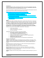
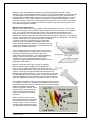
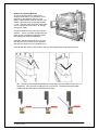
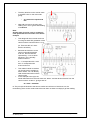
The images below show three examples of how a “datum” enables the marking out process to
proceed.
E102A Notes T2-T12 Version 4 (BG).doc
23 January 2014
Page 28 of 254
Centre Lines
Centre lines are often scribed at required distances from the datum features to establish the
positions of holes, slots, radii, and other details. Holes and radii centres require two centre
lines.
Outlines
Outlines show the dimensions of the work-piece and indicate the location and amount of metal
to be removed. Lengths, widths, thicknesses, angles, diameters, and radii are outlines, which
determine the finished shape.
Finally carefully check all dimensions against the drawing.
Remember, “Measure twice and cut, ONCE!”
NB: If an error in the marking out is found after the fitting operations have commenced, the
probable consequences are wasted time and wasted material.
E102A Notes T2-T12 Version 4 (BG).doc
23 January 2014
Page 29 of 254
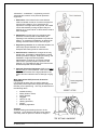
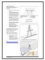
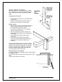
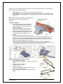
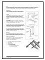
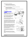
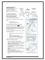
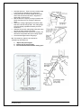
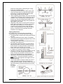
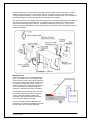
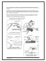
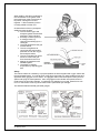
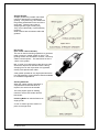
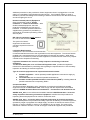
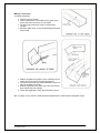
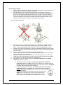
Marking Out from a Datum Edge
If the stock material supplied has an existing
true edge which can be used as a datum then
the development can proceed directly from
this edge as shown to the right.
If there is no true edge, then:
• A datum edge may be a ruled line on
the material as shown above, or,
• Create a true edge by, either:
o Cutting a straight edge using tin
snips for thin gauge sheet metal,
or
o Filing an edge straight for thicker
materials.
Once the datum has been established:
• An engineer’s tri-square is used to
project a “vertical datum line” line at
right angles (90o).
• A steel ruler is then used to develop
from this scribed line.
• A Jenny calliper is used in the bottom
sketch to develop parallel lines.
NB: The key point is that development of the
work piece cannot proceed until firm datum
edges or lines have been established.
NB: The “V” mark is typically used to denote
the “datum line”.
E102A Notes T2-T12 Version 4 (BG).doc
23 January 2014
Page 30 of 254
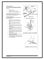
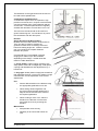
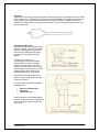
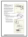
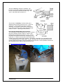
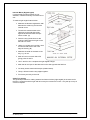
Permanent Outlines
Once the marking out and the checking of dimensions is complete, it is usually necessary to
lightly prick punch fine “witness marks” to permanently indicate the position of the outlines, as
they may become obliterated. Witness marks are especially important when the “marking
medium” eventually rubs off due to handling.
“Witness marks” are light, uniform indents made with a fine prick punch, and punched
accurately on the line work indicating the outlines. When the required fitting or machining has
been completed, only one-half of each witness mark should remain visible.
Once the “witness marks” have been completed, the “centre marks” used for drilling are
deepened at this stage prior to commencing drilling operations.
NB: Examples of the placing and spacing of witness marks are shown below.
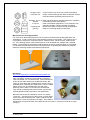
Sustainable energy work practices related to reducing waste when marking out.
Stock materials are sold in standard sizes. Efficient ordering means purchasing stock sizes so
as to obtain the maximum number of job pieces (blanks) out of a stock length. The key is to
eliminate the amount of “off-cuts” which invariably is wasted. When performing the calculation
on usage, always consider the “cut” wastage. For example, a guillotine has a “shear action”
which has virtually no loss, but a saw will have a loss of about 2 mm for each cut. If the job
pieces are small, and there are many “cuts” and this loss can be significant. If the job length is
small, always pre-determine if the stock material can be safely secured after it has been
reduced to a small size. That is, can you safely make the final cut or does this section become
waste also.
E102A Notes T2-T12 Version 4 (BG).doc
23 January 2014
Page 31 of 254
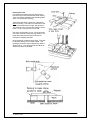
The method used to mark out a sheet will depend on whether it is a one-off task or a production
run. For a “one-off-task” always attempt to use up an off-cut from a previous job if possible and
avoid cutting a “new” sheet. For a production run involving a full sheet, always consider how the
sheet is to be cut. For example, a guillotine will only make complete cuts across the sheet, but
a “gas”, “water” or “laser” cutter can cut virtually any length or shape.
•
•
•
•
If using a guillotine, common edge cutting is a more efficient method as the one action
can produce a number of pieces. But it may also lead to wastage.
Computer controlled machines are able to obtain the optimum cut from a sheet.
Other techniques include, nesting small parts in cut-out holes and making use of
suitable off-cuts where possible.
Always re-check all marking out measurements prior to cutting to ensure no error
wastage.
Tooling
The term “tooling” as applied to the engineering trades refers to any equipment that helps in
the production of a product or any related activity. It ranges from the most fundamental type of
hand tool such as a file to the very complex machine tools such as a computer controlled
machines.
The basic hand tools include:
• Engineer’s Scriber
• Tape measure and Steel rule
• Square, Protractor and Bevel gauge
• Combination square
• Dividers and Jenny callipers
• Scribing block
• Vernier height gauge
• Hammers
• Centre punch and prick punch
Engineer’s Scriber
This tool is designed to scribe (scratch)
very fine marking out lines on to a metal
work piece in preparation for fitting
tasks. It is made from hardened tool
steel which has been ground to a needle
sharp point. The scriber’s point should
be frequently restored so that all
marking out lines are sharp and clear.
When a grinding wheel is used to sharpen a scriber, care must be taken because if temper
colours are raised due to overheating, the point will be softened.
It is better to use an oil stone to sharpen a scriber to avoid spoiling the hardness of the scriber’s
point. A scriber is generally used in combination with a rule, square or straight edge to draw a
single, firm line.
Correct Use
The steps in the correct use of the scriber are as follows:
1. Hold the straight edge firmly in the required position (e.g. steel rule, square, etc.)
2. Incline the scriber away from the straight edge to bring the sharp tip as close to the
straight edge as possible.
3. Incline the scriber slightly toward you in the direction of the stroke.
4. Draw the scriber toward you in one firm stroke.
E102A Notes T2-T12 Version 4 (BG).doc
23 January 2014
Page 32 of 254
Scriber Safety
• Never use a scriber as a substitute for a centre punch.
• Any hand tool which has sharp points or a sharp edge should be guarded when the tool is
stored in the tool storage area. Use either a hardened pouch/sheath or a cork or similar
soft object to protect both the tool and the person who retrieves it.
Protractor and Bevel Gauges
Angular measurement is closely associated with
linear (straight line) measurement. Parts that are
manufactured may have angles or tapers that are
required to fit accurately into mating parts.
Various measuring tools have been designed to
measure angles or tapers in degrees or even
parts of a degree.
Protractors
Protractors have a dial face graduated in
degrees, with a straight blade that can be
swivelled to a specific angle, and then locked in
position.
They are used for:
•
•
•
Setting work to an angle
Testing angles
Marking out the position of holes
Because they are graduated only in degrees,
protractors have limited accuracy.
Bevel Gauges
A bevel gauge consists of a body with an
adjustable sliding blade that may be set and
clamped at an angle to the body of the work
piece.
Use a bevel gauge as follows: •
•
•
•
Set the blade of the gauge to the angle
required
Lock the blade to the body with the
clamping screw
Transfer the gauge on to the work
Compare the setting of the gauge against
the angle on the work
Bevel gauges are used mainly to transfer and to
compare the angle from part to another.
Note how in the illustration above it is being used to compare the drill point angles.
E102A Notes T2-T12 Version 4 (BG).doc
23 January 2014
Page 33 of 254
Engineer’s Square or Tri-Square
This tool consists of a thick body called a “stock”
and a “blade” set to a true right angle (90o) to the
stock. The blade is straight, flat and has parallel
edges.
Tri-Squares are used for:
•
•
Checking that surfaces are at right angles (90o)
to each other,
Setting up work square to another surface a
guide when scribing lines at right angles.
Using a square
• Before using a square, it is important to remove
any burrs from the work and ensure that the
work surface and square are clean.
• Face towards a light source so the light will
•
•
•
•
shine from behind the work.
With your right hand, hold the inside of the
stock of the square against one finished edge
to be tested.
Leave a light gap between blade and the
other edge.
Lower the stock carefully until the blade
comes into contact with the edge of the work.
If the surfaces are square all light will be
excluded.
The adjacent illustration shows a tri-square being
used to check the squareness of a face. This test
should be also carried out frequently so that even
during the roughing down stage the surfaces will
be kept reasonably square with each other and
you will maintain control of the work.
Practical Uses for a Tri-Square
(i) Guide a scriber when marking out lines at right-angles
to the edge of work.
(ii) Determine if two surfaces are at right angles to each
other.
(iii) Check the flatness of surfaces.
E102A Notes T2-T12 Version 4 (BG).doc
23 January 2014
Page 34 of 254
Combination Set
This is a multi function tool comprised of a
“blade”, a “square head”, a “protractor
head”, and a “centre head”.
The “square head” has one face that
forms a right angle (90o) with the blade
and another face which forms a 45o angle
with the blade. The square head and
blade can be used as a:
•
•
•
•
Depth gauge to measure from the
square face to the end of the blade,
Height gauge by setting the square
face flush with the end of the blade,
Square to set work at right angles,
Bevel gauge to set work at 45o
The “protractor head” allows the blade to be set at an angle to the flat face. It is used for
setting up or measuring angles.
The “centre head” is designed to allow one edge of the blade to pass through the centre of two
faces which are at right angles. It can also be used to find the centre of a round object or
checking 450 angles. The images below illustrate how the tool can be used in different
applications.
The examples below illustrate of how the “Centre head” can be used to create an accurate
centre mark for a piece round stock bar. The intersection of the two lines is the “centre” of the
bar.
E102A Notes T2-T12 Version 4 (BG).doc
23 January 2014
Page 35 of 254
The illustration to the right shows how the tool can
be used to draw parallel lines.
Combination Set Maintenance
A combination square set is an expensive, high
precision tool and as such, requires commensurate
care and protection from rough treatment and the
environment. Individual parts should be regularly
cleaned and returned to its case when not in use.
The ruler from the set should not be used as a
generic measuring tool. Its real value is as part of
the combination with the other parts.
Dividers
Spring Dividers and Wing Dividers
Dividers are tools used to scribe circles and arcs.
They can also be used for marking-out
geometrical tasks such as dividing circles and
lines and creating angles etc. Another common
use is to transfer and compare distances
between two points.
Commercially they are available in lengths
ranging from 100mm up to about 300mm
depending on the design. Smaller sizes are
used for smaller dimensions.
A “spring divider” (upper image) consists of two
sharp points at the end of straight legs, held apart by
a spring and threaded rod and adjustment is by a
knurled nut.
A “wing-type” divider (bottom image) has a steel bar
that separates the legs, a lock nut for setting a rough
measurement, and an adjustment screw for fine
adjustments.
Use
•
Set the desired radius on the dividers using
the appropriate graduations on a rule.
•
When setting dividers against a rule,
the points should be kept parallel to the
edge of the rule and set to the centre of
the required graduation.
•
When scribing a circle or arc, lean the
dividers in the direction of movement
and scribe the circle by revolving the
dividers.
Maintenance
• Keep dividers clean and dry,
•
Regularly oil to ensure that it does not
rust,
E102A Notes T2-T12 Version 4 (BG).doc
23 January 2014
Page 36 of 254
•
Protect the points against damage,
•
Store dividers where they will not become bent or broken,
•
Keep the hardened points sharp and care must be taken to keep the two legs at an
equal length.
Jenny Calliper
(Also called odd-leg calliper)
This tool is commonly used to measure and scribe a
development line onto a job surface from an adjacent edge.
It consists of one divider leg and one inside calliper leg
designed to pivot about a point. The tightness of the two
arms is set by a metal thread and flat nut. This is used to
adjust tension the arms.
Practical Uses
(Examples are illustrated in the images
below)
1. To set distances from an edge or
shoulder,
2. For marking out lines parallel to an
edge,
3. For finding the centre of circular
work.
Setting up Jenny Callipers
1. Hold the inward curving leg with
one hand and place it against the
end of the rule,
2. With your other hand, position the
scriber point in the required
graduation,
3. Make sure the ends of both legs
are at equal lengths.
Care:
Always keep the tool well oiled to prevent
rust build-up and protect the needle point
against damage.
E102A Notes T2-T12 Version 4 (BG).doc
23 January 2014
Page 37 of 254
Marking or Scratch Gauge
Ref: http://toolboxes.flexiblelearning.net.au
Practical uses: To set distances from an
edge or shoulder and marking out lines
parallel to an edge.
Using a marking gauge:
¾ Loosen the lock screw on the
headstock.
¾ Hold the headstock with one hand
against the end of the rule.
¾ Move the scriber point to the
required graduation on the rule.
¾ Lock the screw on the headstock.
¾ Hold the headstock against the reference edge of the material.
¾ Draw the gauge along the edge to scribe a parallel line.
Outside and Inside Callipers
These are both precision measuring tools typically used for “fitting” type applications.
They are used in one of two ways:
• The calliper ends are preset to a
definite measurement using a steel
ruler as reference and then the calliper
is compared to the work surface, or
•
The calliper is set to the spacing of the
work surfaces and then compared to
the graduations on the ruler.
Use
To adjust a calliper to a scale dimension, first one
leg of the calliper should be held firmly against
one end of the ruler and the other leg adjusted to
the desired dimension. To adjust a calliper to the
work, open the legs wider than the work spacing
and then bring them down to the work very gently.
Caution
Never place a calliper on work that is revolving in
a machine such as a lathe
Marking Out Equipment
The following basic equipment is used for marking
out:
•
•
•
•
•
•
The marking-off table
Angle plates
Clamps
Vee blocks
Parallel strips
Marking medium
Care:
Always keep these tools well oiled to prevent rust build-up and protect the needle point against
damage.
E102A Notes T2-T12 Version 4 (BG).doc
23 January 2014
Page 38 of 254
Marking-Off Table
The function of the table is to provide an
accurate, flat surface that becomes a datum
surface with respect to the work piece. It also
supports the work at a convenient height for the
person marking-out.
They are constructed from either heavy cast iron
or granite which is then machined and ground
perfectly flat.
The table should be located so that there is
adequate lighting and freedom from obstructions
from all sides.
The marking-off table is used in conjunction with
specialized marking-out equipment such as an
“angle plate” , “vee blocks” or a “scribing block” to
perform precision fitting work.
Care
•
The table’s surface is to be used for
precision work only and you should never
use it for hammering or welding or any
“rough” work etc.
•
Replace the protective cover over the
table when it is not in use.
•
Always protect the surface of a metal table
against rust.
Angle Plates: The working surface of angle plates are
machined at right angles to their adjacent surfaces in
order that work pieces may be held at right angles to
the surface of a marking-off table. Cast iron is the most
likely material from which angle plates are made.
Clamps: To allow the marking out process to take place
without any movement, clamps can be used to secure work to
the angle plate. Light work may be clamped by using
toolmaker’s clamps.
The size of the work piece determines whether to use one or
more clamps. Only light clamping forces are normally
required.
Nb: Magnetic clamps are also available for this task.
E102A Notes T2-T12 Version 4 (BG).doc
23 January 2014
Page 39 of 254
Vee Blocks: Vee blocks are used to hold circular
work when marking out or setting up for machining.
They are manufactured in pairs from cast iron or steel
(hardened). A variety of sizes are available.
Some vee blocks are fitted with a clamp to hold work
securely in position. There are also magnetic vee
blocks where clamps are not required. These provide
the option of securing flat plate at 90 degrees to
working surface or locating round bar for marking out.
Scribing Block (Surface gauge)
This consists of a solid base, machined flat on the
bottom. A vertical column attached to the base
includes a scriber which is located in a moveable
clamp. Its most common purpose on the marking-off
table is to scribe lines on a work piece parallel to the table surface.
It may also be used for:
• Setting up work for machining
• Checking work for parallel
• Finding the centre of work
When using a surface gauge it is important to ensure:
• The scriber point is sharp,
•
The scriber is held as short as possible against the column and always turn the bent end
down for safety,
•
The scriber is kept in a horizontal position as this will be more accurate,
•
To make one clean stroke across the work after setting the correct height,
Safety
When finished with the surface gauge the scriber is clamped parallel to the column with the
main point downward and the curved point inwards.
E102A Notes T2-T12 Version 4 (BG).doc
23 January 2014
Page 40 of 254
Punches
These are made from hardened tool steel.
There are two main types of punches commonly
used in marking out. A “centre punch” and a
“prick (dot) punch”.
Centre Punch
Centre punches are used to locate a centre
position for a hole and make it easier to start a
drill point cutting accurately at that position.
The centre punch has a point angle of between
60-90o and it is used for making an indent on a
work piece to locate the drill point at start.
Prick Punch
Prick punches are used to make light (witness) marks
to better identify scribed lines.
The prick punch makes it easier to:
•
See marking out lines.
•
Check the accuracy of centre positions
before centre punching.
•
Locate the pivot points of dividers for scribing
circles of arcs.
Compared to the centre punch, a “prick punch” has a
sharper point angle of 60o or less and it is used to
make only small marks on a reference line or outline
of a work piece.
E102A Notes T2-T12 Version 4 (BG).doc
23 January 2014
Page 41 of 254
Chalk Line
A chalk line is a piece of string or cord that
is heavily coated with a coloured chalk. The
line is stretched tightly between two points
and then snapped to release a chalky line
onto the target surface. The unit shown is a
self-chalking line.
A mechanical self-chalking line is a
container with the line on a reel. The
container is filled with coloured chalk
powder. The line is automatically chalked
each time it is pulled out and can be 20 to
30m long.
Ref: http://www.toolstop.co.uk/stanley-047-681-fatmax-chalk-line-set-p42363
Application
This is a tool commonly used by an electrical mechanic during installation work.
Applications include:
•
Marking out fixing points for a
cable run,
•
A straight line guide when
installing long rows of light
fittings or;
•
Levelling duct or cable tray.
Technique
• Stretch a taut string line
between the ends of the
proposed run by using
suitable means of fastening,
eg., nails or existing fixings.
This ensures a straight line is
produced.
•
Pull the line perpendicular
away from surface about
100mm and then release.
This action should ensure a
crisp line is produced.
•
The chalk will gradually disappear.
E102A Notes T2-T12 Version 4 (BG).doc
23 January 2014
Page 42 of 254
Plumb Bob
This tool is used to vertically align two points in space. The tool is
weighted object (commonly brass) with a pointed tip that is attached to
a string line. The force of gravity causes the weighted line to hang
vertically, or plumb. Plumb bobs are made in different weights. Always
take care when using it outdoors as their accuracy is affected by the
wind.
To mark a vertical line on a wall
• Hang a plumb bob from a chalk-coated string almost against
the wall (ideally with a tiny gap). Secure the string at the top
point, near the wall, with a nail.
• Steady the weight by hand until it stops swinging and twirling.
• Leave the weight to find its final position.
• Hold the weight against the wall and snap the string against
the wall to create a vertical chalk line.
• Remove the chalk line when no longer
needed.
Applications
There are many applications including:
•
•
Vertical conduit runs
The centring of lighting point to be located
above a dining table.
Spirit Level
A spirit level or bubble level is an instrument
designed to indicate whether a surface is
horizontal (level) or vertical (plumb). Levels are
made in many shapes, sizes and materials to
suit the different trades.
They have in common, a small glass bulb filled
with a liquid which has a small air bubble. When
the bubble is located precisely between the two set
marks then the surface is level or plumb.
Applications
The are countless applications including checking
that switchboards, socket outlets or a conduit or
ducting run is mounted level or vertical.
Sustainable work practice involves
• Maintaining and repairing tools and equipment so that it can operate at high efficiency
and effectiveness,
• Reducing waste products,
• Re-using and recycling materials,
• Responsibly disposing of waste products.
E102A Notes T2-T12 Version 4 (BG).doc
23 January 2014
Page 43 of 254
T4 Holding and cutting encompassing:
¾
¾
¾
¾
common tools for holding (bench vices, multi-grips, vice grips, wrenches).
common tools for cutting metallic and non-metallic material (hacksaws, wood saws,
chisels, pliers, files)
procedure for using a range of tools for cutting, shaping, and finishing metallic and nonmetallic materials
safety procedures when using holding and cutting tools
The electrotechnology industry covers a vast array of tasks and as such there are many types of
hand and power tools that you are expected to recognize, know the characteristics, and use
safely and efficiently. The tools shown in this note are the more common types, but, as you
progress through the industry you will undoubtedly encounter many other specialized tools.
Files
Files are tools used to accurately shape materials by abrading away some part of its surface.
This may be to make the stock match the measurements from an engineering drawing or to
reduce the size of one metal part so that it will fit into or around another. Sometimes, filing is
used to remove rough tool marks left by chipping or machining and produce a high quality
finished surface. Files are made of high grade, carbon tool steel. There are many types in use
with each suited to a specific application.
Parts of a File
The diagram below illustrates the principal parts of a file.
Ref:
https://www.dlsweb.rmit.edu.au/toolbox/electrotech/toolbox1204/resources/03workshop/05hand
_tools/08files.htm
Classification of Files
Files are classified by the following features:
•
•
•
•
•
•
Length
Type of cut
Grade of cut
Longitudinal shape
Cross-sectional shape
Its most common use
Length of a File
This is measured from the “point” to the “shoulder” and does not include the tang which is
inserted into the handle. (See image above). Common types are made in various lengths
ranging from about 150mm up to about 300mm depending on the usage.
E102A Notes T2-T12 Version 4 (BG).doc
23 January 2014
Page 44 of 254
Cut Types
Single cut files have their teeth formed by a
single set of parallel chisel cuts.
Each tooth runs the full width of the side of the
file at an angle to its edge.
These files are used with lighter pressure than
double-cut files and give a smoother finish.
Double cut files have their teeth formed by a
double set of parallel chisel cuts that cross each
other diagonally.
This gives a series of small diamond shaped
teeth.
Dreadnought cut files have very coarse, curved
teeth and are used for cutting soft metals such
as aluminium, lead and fibre glass.
Grades of Cut
The grade of cut is indicated by the pitch or size
of the file’s teeth. The longer the file, the further
the teeth are apart which means that longer files
are coarser than short ones.
The common grades used are “flat smooth”, flat
second cut” and “flat bastard”.
Note: A “bastard file” is a file whose teeth
configuration is rougher than a 'second cut' file and is ideal for quickly removing excess metal
on a surface.
File Shapes
Ref: http://www.pferdusa.com/products/201a/201a15/201a1503P.html
Hand file
The “hand file” has the same cross-sectional dimensions as the “flat file” (shown further below)
but has a blunt end shape as the “flat file” has a tapered end. Hand files are parallel in width,
but do taper in thickness to the end. They are somewhat thicker than flat files. This type is
double cut, and normally has one “safe edge” (uncut) which permits filing one surface without
affecting an adjoining one. They are used for general filing work.
Flat File
Tapered in width at the point and slightly tapered in thickness at the point. Flat files are double
cut on both sides and are single cut on the edges. Flat files are general-purpose files.
E102A Notes T2-T12 Version 4 (BG).doc
23 January 2014
Page 45 of 254
Mill File
This type has two square edges. Mill files are tapered in both width and thickness. One edge
has no teeth. Ie. “Safe edge”. Mill files are used for smoothing work, draw-filing, and other fine
precision work. Mill files are always single-cut.
Warding File
This file can be used for narrow slotting and working on intricate shapes. It is double cut,
parallel in thickness, tapered in width, and quite thin. Like a hand or flat file that comes to a
point on the end. Used for flat filing work.
Round (Also called a Rat Tail file)
This file is used for enlarging circular holes or rounded grooves that are too small for a half
round file. It tapers toward the point making it adaptable for use on various size holes. Round
files are gradually tapered and are used for many tasks that require a round tool.
Half Round File
This file is used for filing out concave surfaces and crevices, and for rounding out holes. The
spiral cut enables them to remove metal rapidly and leaves a smooth finish. Some half round
files taper in width and thickness, coming to a point, and are narrower than a standard half
round file.
Square File
This file is used for filing slots, keyways, and rectangular as well as square holes and for surface
work, this file has four equal sides. Double cut, it tapers toward the point.
Triangular (Three Square or Three Cornered) File
Three square files are triangular in cross-section and are double cut and have fairly sharp
corners that are slightly set and cut. These files are used for filing internal angles more acute
than the right angle. Three corner files (triangular) have a triangular cross-section, which
gradually tapers. Some files taper all the way to a point (especially small ones). They are used
for many cuts, such as cutting angles less than 90 degrees. They are often employed to
sharpen the teeth of wood saws.
E102A Notes T2-T12 Version 4 (BG).doc
23 January 2014
Page 46 of 254
Rasp
Rasp files are tanged for blacksmith type work. They are flat with a rasp cut on one side
(upstanding teeth arranged in rows with curved cutting edges of generally pyramidal shape and
have a cutting face with a positive rake or slope) and a double cut file on the reverse side. They
are used for removal of soft materials such as wood.
Dreadnought File
Dreadnought files typically have very coarse curved teeth. They are used for rapidly removing
large quantities of material from thick aluminium alloy, copper or plastic epoxy filler materials.
NB: A tradesperson’s toolkit is not complete unless it contains an assortment of file types.
Jeweller’s Files
Kits of small files, often called "Swiss Pattern" or "Jeweller’s" files, are used to fit parts of
delicate mechanisms, and for filing work on instruments. Always handle these small files
carefully because they break easily.
E102A Notes T2-T12 Version 4 (BG).doc
23 January 2014
Page 47 of 254
File Handles
The tang of a file is designed to fit tightly into a
suitably sized file handle. It is designed as a tapered
fit. The file handle is typically made of strong highimpact material, contoured to fit the hand for straight
or draw filing.
Each file must be fitted with a handle for two reasons:
1. To prevent the sharp long tang from piercing the
hand.
2. To give better control over the pressure and
direction of the file.
Both wooden handles and plastic handles are
common. Long files require a long handle and vice
versa. The handle must fit firmly onto the tang and
must not be loose.
How to use a File
Cross filing. Use long steady strokes of medium
pressure made at about 40 to 50 strokes per minute.
If the pressure is too light, or the file speed too great,
then the file tends to slip over the work without cutting.
Slipping damages the file’s teeth. Always use enough
pressure so that you “feel” the file cutting.
For heavy filing increase the pressure and decrease the speed of filing. If the work is very soft,
or its surface very narrow, use less pressure and a greater speed of filing.
NB: A file with a “safe edge” is commonly used to ensure that material from an adjacent surface
is not removed while filing close by.
E102A Notes T2-T12 Version 4 (BG).doc
23 January 2014
Page 48 of 254
Draw Filing
Draw filing is a technique that can be used as a final
finishing process on parts that are longer than they are
wide. This method is only used when the work is
nearly flat and close to its final size. It produces a
smooth, even surface with all the file marks running in
one direction.
To “draw file” use the following procedure:
•
•
•
•
•
•
Balance the file across the work at right angles to
its length.
Grip the file with both hands as close as possible
to the work, with your thumbs on the rear edge and
your fingers on the front edge.
Make sure you keep the file level and move both
hands at the same time.
Make the cutting stroke by moving the file directly
forward using light pressure.
Don’t use heavy pressure on the file on the return
stroke.
Continue at a speed suited to the job.
Fitting the File Handle
Two methods can be used when fitting wooden file
handles: •
•
•
•
•
•
An axial hole is first drilled in the handle with a drill
that has a diameter equal to the width of the tang at
its mid point.
The tank is then inserted into the hole of the
handle. With one hand hold the body with the file
upright. Steady the file with the other hand.
Bring down the handle sharply on a solid bench top.
Alternatively, a small diameter pilot hole is drilled
axially in the handle. Then the tang is heated while
the blade is protected by a wet cloth.
When the tip of the tang is red hot, it is pushed into
the handle to a depth of three quarters of its length
and then withdrawn.
Once the tang is cool, it is reinserted into the hole
and firmly fixed in the handle.
Inserting a file in a plastic handle
• File three grooves in the tang
• Heat the tang until it is cherry red
• Push it into the plastic handle. The heat will melt
the plastic into the grooves and solidify when it
cools.
File Storing and Safety
Files are fine cutting tools. To cut well, they must be
kept clean. Because they are tempered and hard, they
are also very brittle and easily damaged.
E102A Notes T2-T12 Version 4 (BG).doc
23 January 2014
Page 49 of 254
To care for files ensure that you follow these rules
• Keep files clean and dry,
• Never put oil on the teeth of a file!,
• Never strike a file on a solid metal surface or strike it with a metal object, (it could shatter).
• Never bend a file or exert excessive pressure on it,
• Store files separately from each other and from other tools, (ie: Wrap in cloth or paper to
protect cutting teeth)
• Make sure that file handles are sound and firmly fitted.
File Card
“Pinning” (Scratching) occurs when particles of metal or
other material become wedged in between the teeth of a
file. These particles stand higher than the teeth and
cause scratches in the work surface. The effects of
pinning can be minimized by rubbing soft teacher’s chalk
into the face of the file prior to starting filing.
Pinning commonly occurs when too much pressure is
applied to a “new” file. If pinning is occurring, then the
“pins” can be removed from the file’s teeth by using a
small stiff brush known as a “file card”. Brush in a
direction “parallel” with the teeth for best results.
Emery Paper
To achieve an extra-smooth finished surface after
filing, place a piece of emery paper (abrasive cloth)
length-ways under the file with its rough-side-out.
Then use the file such that the work surface “grain” is
directed in one direction. To finish, reverse the emery
paper, (ie. smooth side out) and “burnish” (polish) the
surface.
De-burring Tool
Ref: http://www.rapidonline.com/ToolsEquipment/Deburring-Tool-with-Spare-Blade302092
The tool shown to the right is designed to “de-burr” the
edge of a hole after filing or drilling. It has a solid
carbide blade. The technique is to run the cutting
edge of the tool along the edge of the work piece to form a small bevel and make the edge
smooth. This model works equally well for curved surfaces.
File Safety
• Always wear eye protection when filing.
• Never use a file unless it is equipped with a tight-fitting
handle. A file without a handle could result in the tang
being driven into your hand. The file handle also will
also give you better control and a more accurate cut.
• Never use a file with a loose handle as it may come off
while in use.
• Never use a file as a lever or hammer. The hardened
steel is very brittle and will snap and this could cause
personal injury.
E102A Notes T2-T12 Version 4 (BG).doc
23 January 2014
Page 50 of 254
Handsaws
There are a number of different types of hand saws
used in the electrotechnology industry. Listed below
are the more common ones.
Hacksaw
The basic hacksaw is used to hand cut most solid
materials including metals and other dense nonmetallic materials. Eg: Plastics and Perspex, They
are not effective when used to cut timber.
A hacksaw consists of a flexible hardened steel
blade and an adjustable frame with the blade held
under tension.
Saw blades are made of carbon steel or high speed
molybdenum (more expensive). The teeth of the
saw are hardened while the back of the blade is just
annealed.
Parts of a hacksaw
Most hacksaws have an adjustable frame so it may
accommodate blades of different lengths of blades.
A set screw or catch allows the bow to be set in
different positions in the handle.
Hacksaw blades
General purpose blades are made in lengths of
230mm, 250mm and 300mm.
The number of teeth per inch (25mm) also varies for
each application. This ranges from 18 to 32 teeth
per inch.
When choosing a blade for a task, as a rule of
thumb, there should be at least “two” teeth in contact
with the cut surface at all times.
When cutting, employ long steady slow strokes,
using as many teeth as is possible to do the cutting.
Short, fast strokes with uneven pressure will only
result in a dulled or broken blade.
The cut is made on the forward stroke, only and NOT
on the backward stroke.
Therefore, when cutting mild steel with a hand
hacksaw, you should apply downward pressure on
the forward stroke only.
Do not twist or bend the blade when cutting because
this could cause it to break.
E102A Notes T2-T12 Version 4 (BG).doc
23 January 2014
Page 51 of 254
Selecting Blade Pitch
The blade “pitch” for different types of work is shown below. The blade’s teeth should be flat
across the work. A blade with the correct number of teeth will provide chip clearance.
As general rule, “two-or-more” teeth should always be in contact with the work surface while
cutting. If a coarse blade is used on a thin section, then the teeth will straddle the work making
cutting difficult and cause the teeth to break. Eg: This is very common when cutting thin walled
pipe.
But, if the tooth pitch is too fine then the blade cannot “clear” the material as it is removed. It will
become clogged and will not cut efficiently.
Recommended Pitch Usage
NB: TPI (Teeth per Inch)
• 14 TPI Use for machine, cold-rolled,
or structural steel..
• 18 TPI Use for solid stock,
aluminium, tool steel, high-speed
steel, cast iron, and the like.
• 24 TPI Use for angle iron, brass,
copper, iron pipes etc.
• 32 TPI Use for conduit and other thin
tubing and sheet metal work.
Hand hacksaw blades are generally 12mm
wide and 0.7 mm thick. The “kerf” is wider
than the blade’s thickness because of the
set of the teeth.
NB: The “kerf” is the width of cut, groove
or incision made by the blade.
The “set” of a blade refers to the offset of
teeth outward from the blade itself. Two
kinds of sets are found on hand hacksaw
blades; the “straight/alternate” set and the
“wavy” set.
A wavy set is found on most fine-tooth hacksaw blades.
E102A Notes T2-T12 Version 4 (BG).doc
23 January 2014
Page 52 of 254
Fitting a blade
NB: A hacksaw blade should be inserted into the frame
with its “teeth” points facing “forward” to enable it to cut on
the forward stroke. Ie: Teeth point away from the handle.
•
•
•
•
•
•
•
•
Set the frame to the correct length to suit the blade.
Hold the handle in one hand and check that both pins
face the same direction.
Hold the front of the blade in the other hand with the
teeth facing towards the front of the frame.
Fit the blade on the pin near the handle and steady it
with your thumb then fit the blade on the other pin.
Use your thumbs to press the blade hard against the
flats of the blade holders and tension the blade with
the wing nut. Take up the slack then give three full
turns on the tensioning nut.
Check the tension – the blade should “ring” sharply
when the back of the blade is plucked with your thumb
nail. If the blade flexes sideways when cutting, more
tension is needed.
The saw blade may break if it is too loose in the frame
or if the work piece slips in the vice while sawing. Too
much pressure may also cause the blade to break.
A badly worn blade, one which the set has been worn
down, will cut too narrow a kerf, which will cause
binding and perhaps breakage of the blade.
NB: If you are forced to use a new blade to finish a cut,
turn the work piece over and start with the new blade from
the opposite side and make a cut to meet the first one. The
set on the new blade will be wider. Forcing the new blade
into an old cut will immediately ruin it by wearing the set
down.
Cutting with a hacksaw
Holding the hacksaw
At all times control the hacksaw with both hands and keep
it straight and upright. Do not allow the blade to twist or
move sideways.
Stance
• Stand in a comfortable, well balanced position
approximately 400 – 500mm behind the vice with the
right foot perpendicular to the line of the cut.
• Allow the body to rock forward and back with each
stroke keeping the right arm close to the body with the
forearm in line with the blade.
• At the beginning of each stroke most of the pressure
will be directed from the left hand.
• Gradually transfer the pressure to the right hand by the
end of the stroke.
E102A Notes T2-T12 Version 4 (BG).doc
23 January 2014
Page 53 of 254
NB: Both the type of material and the section to be cut are general factors to be considered in
selecting the pitch of blade required.
•
•
•
Soft material - use a coarse pitch to give ample chip clearance.
Hard material - use a fine pitch to give sufficient cutting points in contact with the work.
Thin sections - use the finest pitch to ensure a minimum of three teeth in contact with
the work.
Note: Blade manufacturers supply precise tables of
the type and pitch of blade to suit specific
materials.
Cutting Techniques
• A cut on a work piece should be started
with only light cutting pressure, with the
thumb or fingers on one hand acting as a
guide for the blade.
• Sometimes it helps to start a blade in a
small vee-notch filed into the work piece.
• When a work piece is supported in a vice,
make sure that the cutting is done close to
the vice jaws for a rigid setup free of
chatter.
• Work should be positioned in a vice so that
the saw cut is vertical. This makes it easier for the saw to follow a straight line. At the
end of a saw cut, just before the pieces are completely parted, reduce the cutting
pressure or you may be caught off balance when the pieces come apart and cut your
hands on the sharp edges of the work piece.
• To saw thin material, sandwich it between two pieces of wood for a straight cut.
• Avoid bending the saw blades, because they are likely to break, and when they do, they
usually shatter in all directions and could injure you or others nearby.
Blade/Tooth Breakage - Common causes
• Work insecurely clamped.
• Pitch of saw too coarse (too few teeth in contact with
work).
• Incorrect tension on blade.
• Starting a cut on a corner.
• Pressure too great.
• Failure to reduce pressure at the finish of a cut.
• Twisty or jerky sawing action.
• Using new blade to finish a cut started with worn
blade.
E102A Notes T2-T12 Version 4 (BG).doc
23 January 2014
Page 54 of 254
Safety Considerations
• Always wear safety glasses to avoid chips entering eyes.
• Ensure the blade is correctly tensioned and that the teeth point away from the handle.
• Clamp the job close to the saw line to avoid excessive vibration.
• Support the over-hang as the cut is nearly completed.
• When cutting, always have in your mind that the blade could shatter at any time and
your balance is the only thing
preventing your knuckles from injury.
Junior hacksaw
A junior hacksaw is used to cut light gauge
metal or rigid plastic such as PVC conduit
etc. This is a small steel framed tool in which
the spring tension of the frame itself holds
the blade in place. The blade must be fitted
with the points of the teeth facing (forward)
away from the handle, so it will cut on the
forward stroke.
Pad Handle
A pad handle is made of a light alloy or a rigid plastic and has a securing nut designed to hold a
piece of a standard hacksaw blade. It is used to make a cut in tight confined spaces or
situations where you are unable to access the space in behind the object to be cut.
A small section of hacksaw blade protruding from the handle is easier to control.
Coping Saw
http://en.wikipedia.org/wiki/Coping_saw
A coping saw is a type of hand saw used to cut intricate shapes in sheet materials. The blades
are thicker and much coarser than a junior hacksaw blade.
A coping saw consists of a thin, hardened steel blade, stretched between the ends of a square,
“C”-shaped, springy-iron frame to which a handle is attached.
•
A coping saw blade is removable by partially unscrewing the handle. Retightening the
handle tensions the blade and locks it at the desired angle relative to the frame.
•
The blade is prevented from rotating by means of the short, steady bar provided where
the blade is attached.
Loosening the handle also allows the blade to be rotated relative to the frame as
desired.
•
E102A Notes T2-T12 Version 4 (BG).doc
23 January 2014
Page 55 of 254
•
•
•
•
•
Aligning the finger steady bars at the top and bottom of the blade ensures that the thin
blade is straight and not twisted along its length.
The direction of the cut is easy to change because of the thinness of the blade. Gentle
curves are achieved by slowly turning the whole frame by means of the handle while
continuing to cut steadily.
The blade can also be rotated with respect to the frame to make sharper curves in the
material being cut.
The teeth on a coping saw blade should normally face the handle. (i.e.” face
backwards" as compared with most other hand saws); the action of pulling the coping
saw allows the frame to remain in tension (and thus reduces blade breakages). This
technique is opposite most other saws which cut on the "push" stroke.
Coping saws are used for cutting a range of soft materials such as wood, acrylic, and
aluminum.
Keyhole Saw
(Compass Saw or Plaster Saw)
This is a long, narrow and tapering rip saw designed to
cut sections from boards or panels.
It is commonly used in the electrotechnology industry
to cut small holes in plaster board to accommodate
socket outlets and light switches.
It consists of a pointed 150 to 180mm tapered blade
with rough pointed teeth usually with a wooden handle.
The point is usually sharp enough to penetrate soft
plaster board directly without the need to pre-drill.
Safety: Use extreme caution when cutting plaster
board on an existing house as there may be live
conductors directly behind the plaster panel. Always
turn off the power to the area before cutting. Also,
plaster board dust could be a health hazard. Wear a
“safety face mask” when performing this task.
Hand Saw (Wood)
(Cross-Cut or Rip Saw Types)
This type of hand tool is designed to cut mainly timber based
products.
The teeth of “rip saws” are designed to cut timber of medium
thickness with the grain and the teeth of “cross-cut” saws are
designed to cut timber across the grain and also general
cutting. Start a cut by slowly drawing the saw up a few times
to make a notch. Once started the saw blade itself assists
guiding the blade straight for the remainder of the cut.
Uses in the electrotechnology industry include cutting
battens used for clipping cable, cutting out studs to mount air
conditioners and making noggins to support ceiling mounted
light fittings. Blade length: 550m to 700mm. Tooth size: Six
points per 25mm is recommended for general-purpose
applications.
E102A Notes T2-T12 Version 4 (BG).doc
23 January 2014
Page 56 of 254
Hand Saw Maintenance
• Keep the surface of the saw coated with a light lubricant to ensure that it does not rust.
• Ensure that the teeth do not contact other steel based tools as this will damage them.
Hole Saw
This tool is designed to cut neat round holes in variety materials
of diameters larger than is possible with a normal twist drill.
Typical sizes range from diameters of about 18mm up to about
75mm in diameter.
A hole saw is a circular shaped saw blade that is used in a
powered drill. They typically have a pilot drill bit (approximately
6mm diameter) at their center to keep the saw teeth from
walking during the cut. Sometimes there is a coil spring located
around the drill bit to expel the core material from the saw after
the hole is completed. Most hole saws have a fairly short aspect
ratio of diameter to depth, which means they are used to cut through relatively thin work pieces.
Because of their high peripheral speed it is important to use a lubricant to stop the teeth from
over-heating when cutting sheet metal.
Safety
Always wear appropriate PPE, especially safety glasses.
Applications
They are many applications including mounting indicating lights, push buttons and instruments
for switchboard panels. They are also used to cut large diameter holes in a variety of materials,
to facilitate cable or conduit entry etc.
Fly Cutter
(Circle Cutter)
This tool is designed to cut very large diameter holes in
flat materials such as sheet metal or plastic etc. It is
ideal for hole sizes greater than can be cut using a hole
saw.
A fly cutter is composed of a spindle, horizontal bar with
a securing screw for a lathe tool bit. A clearance hole
must be drilled to enable the spindle to rotate freely in
the stock material.
As the entire unit rotates (extremely slowly) the tool bit
takes a broad, shallow cut. The material to be drilled must be clamped flat and very secure and
the spindle rotated at the slowest possible speed. This tool is often used with a “radial arm drill”.
Wad Punch
Because the leading edge is very sharp, it enables this tool
to cut neat holes in soft sheet material such as plastic,
fibre, felt or lead. This makes it suitable for making
“gaskets”.
Wad punches are produced with hole sizes ranging from
5mm to about 40mm using high grade steel.
To use a wad punch, first place a piece of soft timber as
backing behind the sheet material and align it with the point of contact. Align the wad punch
carefully with the centre line cross and strike the end of the punch cleanly with a hammer. If
sharp, it should cleanly remove the centre section from the material.
E102A Notes T2-T12 Version 4 (BG).doc
23 January 2014
Page 57 of 254
Metal Punch (Chassis Punch)
This tool is used to cut neat holes, up to about
40mm diameter in sheet metal or gasket material
with a thickness not greater than 1.6mm.
This tool is often used to cut conduit access holes
in the sides of electrical switchboards. First drill a
clearance hole for the bolt. Locate the cutting
head on the inside and the recessed section on
the outside. Thread the bolt through and begin to
tighten using an “Allen Key” or ring spanner
depending on the design.
When the cutting head passes through the metal it
leaves very little burr. Because it produces little
heat, it does not affect painted surfaces.
Cold Chisel
Cold chisels are designed to cut thick sections of
metals such as steel, but it can also be used to cut
products such as masonry bricks and concrete.
They are made of carbon tool steel or of alloy tool
steel. They are forged to the shape and size
required, then hardened and tempered. They
should be tough enough to withstand the impact of a heavy blow, yet sufficiently hard to
maintain their sharp cutting edge.
A cold chisel could be used to chip away
excess metal, or to split a piece of metal that
can not be cut by hand with a saw or grinder.
Common Types of Chisels
Chisels designed to cut metals are usually
classified by the length of the stock, the width
of the cutting edge, and the type.
Examples are: 180 x 25 mm, flat chisel and
the 150 x 6 mm, cross cut chisel
E102A Notes T2-T12 Version 4 (BG).doc
23 January 2014
Page 58 of 254
Types of “metal” chisels
The most common is the flat chisel which is used for chipping flat surfaces, trimming, cutting
thin sections of metal. General applications include cutting off rivet heads and bolt heads and
splitting nuts when dismantling machinery.
Less common chisel types include:
The cross cut chisel which is used for cutting key
ways and grooves requiring a flat bottom and
square walls.
The round nose chisel
which is used for cutting oil
grooves in bearing surfaces,
and also for drainage
channels.
The diamond point chisel is
used for cutting V shaped
grooves and sharp corners,
as well as for preparing
cracked parts for welding.
Danger: Always wear safety
glasses when using a metal
chisel as pieces of metal can
become projectiles.
Cutting Angle on “Flat” Chisels
The cutting angle (cutting edge) is usually formed by two
bevels or facets equal in angle and width. The average
cutting angle is 65°, but may be varied from 55° to 85° to suit
the metal to be cut. The harder the metal to be cut, the
stronger, and larger must be the cutting angle.
Commonly used cutting angles are:
Brass Mild
50° - 60°
Steel
60° - 70°
Cast Iron
70° - 80°
Sharpening a Chisel
A chisel made of carbon tool steel is normally
sharpened on a grinding wheel. Care should be
taken not to apply too much pressure, nor to keep it
against the wheel for too long before cooling it.
(eg. Water)
If the chisel is overheated (where its tip changes to
a blue colour) then the temper of the steel will be
drawn, and the chisel will be too soft to use.
Always wear safety glasses when using a grinder.
Chisels should be ground on the front face of the
wheel. Always point the chisel facing upwards
towards the wheel estimating the required angle.
The wheel should be fitted with a spark guard, and safety glasses must be worn.
E102A Notes T2-T12 Version 4 (BG).doc
23 January 2014
Page 59 of 254
Wood Chisels
These are designed to cut timber or other soft
materials. These are made in a variety of types and
sizes. They have either a wood or plastic handle
(plastic being the more suitable material for use with
a steel hammer).
The blade has parallel sides and tapers in
thickness. Blade widths from 6mm to 50mm are
available. Some uses include:
•
•
•
Cutting recesses for architrave dimmer
switches.
Cutting recesses in skirting for socket
outlets etc.
Cutting rebates in studs or noggings to
accommodate cables.
Safety Precautions for Wood Chisels
• Replace cracked or split handles.
• Never use a wood chisel as a lever.
• Make sure the work is braced or supported.
• Never place your hand where it could be
cut if the chisel slipped.
• Always cut away from your person.
• Use a sheath to protect the tip while
it is being stored.
Bolster Chisel
A brick layers “bolster” chisel is designed to
cut masonry bricks in two. It is commonly
used in conjunction with a “lump hammer”.
It has a blade 65mm wide.
Star Drill
Classified as a chisel because of its impact cutting action
when struck with a hammer, the star drill finds its main use
in cutting round holes in concrete or brick work. Brackets
supporting switchboards, motors and cable tray can be
secured to fixing devices that have been inserted into the
concrete or masonry etc.
It can be used in situations where a masonry drill is not
available.
E102A Notes T2-T12 Version 4 (BG).doc
23 January 2014
Page 60 of 254
Chisel Safety Precautions
• Always wear safety glasses.
• Never chip towards yourself and protect
others with screens.
• Do not use a chisel that has a crack or a
flaw.
• Check that the hammer is in good condition.
• Make sure your hands, the chisel and
hammer are clean and dry and free from
grease.
• Watch the cutting edge of the chisel, not its
head when hammering.
• Make sure that the size of the chisel and its
cutting angle is correct for the job.
• Never use a chisel with a mushroomed
head as it can easily chip and splinter and
become a hazard. . The “mushroomed”
section should be ground back using a
bench grinder to an approximate shape as
shown to the right.
Tin-Snips
This tool is used for cutting “light-gauge” materials
such as sheet metal. They are typically used in the
electrotechnology industry for installing cable tray
and metal duct.
Tin snips will cut slightly heavier gauges of soft
metals such as aluminium alloys or copper sheet.
The linkage of compound-action type tin snips
increases the mechanical advantage without
increasing the length of the snips.
Tin snips are made with either “straight”, “bent” or
universal cutting jaws.
•
“Straight” cutting snips are used to cut in a
straight line and wide curves;
•
“Right” snips will cut straight and in a tight
curve to the right.
•
“Left” snips will cut straight and in a tight
curve to the left;
•
“Universal” snips cut will cut in both
directions.
These different cutting styles are necessary
because metal is stiff and heavy and does not
move out of the way readily when cutting around
a curve. The respective styles move the material
out of the way when cutting in the direction they
are designed for. The blades are usually serrated
to prevent material slippage when cutting.
E102A Notes T2-T12 Version 4 (BG).doc
23 January 2014
Page 61 of 254
Use
Grip the handles between the thumb and the first finger and allow first and second fingers to curl
around the lower handle. Place the third and small fingers between the handles, but rest them
on top of the lower handle. This gives good control to open and close the cutting jaws..
Application
Cutting large cable entry holes for switchboards,
notching cable tray and cable duct during installation.
Clamps
A wide variety of clamping tools are used in a metal
workshop. Each clamp has a variety of uses in
situations which require the holding or aligning of
materials in readiness for drilling, riveting, screwing or
welding.
‘G’ Clamps
A ‘G’ clamp is designed to temporary clamp two or
more objects together. Its main body is drop forged
from high quality steel in the form of a ‘G’.
The top of the ‘G’ forms the fixed upper jaw while the
lower jaw is adjusted by turning the threaded shaft.
Depending on the way it is turned, it will either increase
or decrease the pressure between the jaws.
‘G’ clamps are available in a variety of sizes ranging
from 50 mm to about 300 mm capacity. They are also
made in different weights and strengths for general
purpose, medium or heavy duty.
Warning
Do not increase the pressure between the jaws by
applying a greater leverage than the clamp is designed
to take, as this will distort and damage the clamp.
Other Types of Clamps
Apart from the “G” clamp, many other clamps are
available, some designed for specific uses.
Below is a list of these clamps:
•
•
•
•
Toolmaker’s clamp (shown to the right)
Sash clamps
Spring clamps
Adjustable Vice grips
¾ Vice grip pliers
¾ Vice grip welding clamps
¾ Flat nose vice grips
E102A Notes T2-T12 Version 4 (BG).doc
23 January 2014
Page 62 of 254
Adjustable Vice Grips
These pliers form an adjustable portable
clamp with serrated jaws designed to hold
narrow objects. It is adjusted by the knurled
screw located at the end of the handles.
Application
This tool can be used as a temporary clamp,
a wrench or a portable vice to hold items for
drilling, grinding and welding etc.
Multi-Grip Pliers or Slip Joint Pliers
This tool is used as light duty pipe wrench
and is ideal for assembling metal conduit
work. They have a shaped pivot pin which
can fit into two or more openings in the legs.
This gives a range of jaw openings which
allows parallel gripping by the jaws in a
number of positions.
Multi-grips are designed to grip “round”
objects such as rods and pipes and should
not be used to turn hexagon headed bolts or
nuts.
Stillson
(Also called Pipe Wrench)
This tool is used for gripping and turning metal
pipes or conduits. It has much greater gripping
force than can be provided by multi-grip pliers.
Fixed to the handle is a jaw with outward facing
teeth. Attached to this handle by a pivot pin is
a spring-loaded casing that carries a knurled
adjusting nut. This engages with a thread on
the adjustable arm of a jaw with inward facing
teeth.
Once the jaws are adjusted, the spring loading
keeps them in contact with the work and the
toggle action causes the hardened serrations
to bite into the work.
E102A Notes T2-T12 Version 4 (BG).doc
23 January 2014
Page 63 of 254
Footprint Pipe Wrench
This tool is used for gripping and turning pipes or conduits. It does not have the gripping force
of Stillsons, but takes much less time to set up.
One folded steel handle has outward facing teeth cut in a convex jaw. The other solid steel
handle has inward facing teeth cut into a straight jaw. Adjustment for differing diameters is
made by fitting the removable pin in a hole that will allow the pipe to be gripped properly, without
the two handles of the wrench being too far apart.
Application: Multi-grips, footprints and
Stillsons are used for gripping and
turning pipes or conduits.
Note: As pipe wrenches tend to `bite-in'
they will invariably mark the surface on
which they are used. Therefore, they
should not be used on polished or
plated surfaces (Here use a strap
wrench).
Any burrs left on the surface should be
filed off. Any damaged surface of
galvanized metal conduit should be
refurbished with paint to avoid the onset
of rust.
Torque Wrench (Tension Wrench)
A torque wrench is used in situations where a prescribed amount of torque (turning force) is
specified for the final tightening of a fixing bolt. A torque wrench has a square drive which fits
standard sockets and can be preset to release at a predetermined torque in “Newton/Metres”
(Nm). In the electrotechnology industry, they are used to tension nuts on busbars, electric
motors and machinery etc.
The amount of force required to turn a fastener is directly related to the tensile stress within the
fastener. In Australia, torque is measured in Newton/ Metres, but for imported equipment,
torque values may be given “psi” (Pound per square inch). A torque wrench should only be
used for tightening operation and not to loosen nuts as this will affect its accuracy.
Common types of torque wrench include: “Beam”, “Deflecting beam”, “Click” and “Electronic”.
The “Click” type torque wrench clicks a button when the selected torque is reached. This type is
shown below.
E102A Notes T2-T12 Version 4 (BG).doc
23 January 2014
Page 64 of 254
Electronic Type Torque Wrench
Ref: http://www.google.com.au/imgres?
This design provides a digital readout of the torque being exerted.
Bench Vice
During disassembly work an engineer’s “bench vice”
can be used to hold parts while they are being
processed.
A bench “vice” is fabricated from steel or cast iron
and consists of two jaws; one “fixed” or stationary
and one moveable. These are fitted into a frame
with a heavy screw apparatus operated by a lever
which controls the moveable jaw, allowing the space
between the jaws to be expanded or contracted to
accommodate different-sized pieces of material.
The size of a vice is set by the width of the
“jaws”. Common sizes range from 75mm to
150mm and with jaw openings from 100mm to
200mm.
As shown to the right, some designs have
“offset” jaws to enable them to hold long lengths
of stock vertically.
E102A Notes T2-T12 Version 4 (BG).doc
23 January 2014
Page 65 of 254
Vice Jaws
“Hard jaws” are replaceable case hardened steel blocks fitted by two metal threads. The
gripping faces of the jaws are serrated to provide excellent grip.
“Soft jaws” are made of plastic (polyurethane) or
aluminium and have a magnetic strip to secure
them in place over the steel jaws. Most
workshops use soft jaws from bent “L” shaped
inserts of aluminium. These help avoid
damaging the surface of soft materials or threads
etc.
Care and Use of a Vice
• Ensure that the vice is securely fixed to
the work bench,
• Clamp the work piece evenly in the vice,
• Support the ends of long piece of material held in the vice,
• Do not use the vice as a hammering surface as it is not designed to function as an
“anvil”. The movable jaw is usually made of thin cast iron can easily crack.
• Heat should not be applied to work held in the jaws as the hardened insert jaws will
become softened.
• The force of bending should be against the fixed jaw rather than the movable jaw of the
vice.
• Bench vices should occasionally be taken apart so that the screw, nut, and thrust
collars can be cleaned and lubricated. The screw and nut should be cleaned in
• Solvent and a heavy grease should be packed on the screw and thrust collars before
reassembly.
• When it is not being used, partially close up the jaws, but, not fully tightened. NB: If a
vice is left too tight, any expansion or contraction due to temperature change could
crack the frame.
Workshop Equipment
A fixed machine tool refers to a power driven machine mounted in a permanent location. Most
“fixed” workshop equipment is electric powered. Be aware; if an electric powered tool “stalls” for
a length of time, then the current drawn by the
motor will increase substantially. This may cause
the motor to burn-out and it could cause a fire.
Workshop tools function by:
•
•
•
•
Holding the material to be cut,
Holding the cutting tool or tools,
Moving or rotating the work, the tool, or
both, so that the parent material is
removed.
Controlling the speed, magnitude and rate
of the cut.
The word “machining” means the cutting away of
material by means of a power driven machine tool.
Typical fixed workshop machine tools include a:
• Pedestal or Bench grinder,
• Bench (Pedestal), Pillar or Radial fixed
drilling machine,
• Metal Lathe,
• Abrasive saw,
• Cold saw,
E102A Notes T2-T12 Version 4 (BG).doc
23 January 2014
Page 66 of 254
•
•
Vertical Band saw,
Power hacksaw,
Safety
There are identifiable hazards associated with all machine tools as part of their operation and
use. To reduce the level of risk it is essential that you:
•
•
•
•
Are suitably trained in its correct use and that you DO NOT perform any task that is
outside the scope of your training,
Are supervised closely when new to a machine,
Wear all PPE (Personal Protective Equipment) that is deemed necessary for the task,
Strictly follow ALL of the safety guidelines.
Off-Hand Grinding
Off-hand grinding is the term used in engineering to describe the process where the work is held
by hand and surplus material is removed using an abrasive grinding wheel.
This type of grinding is carried out in the workshop to:
• Dress metal,
• Rough shape parts,
• Remove excess metal,
• Prepare plates for welding,
• Smooth surfaces.
Off-hand grinding is also used for sharpening cutting tools such as:
• Twist drills,
• Chisels and scrapers,
• Punches and scribers,
• Lathe cutting tools.
Safety
Always wear safety goggles or an approved type of eye protection when performing any
grinding operations.
Important: Leather gloves must NOT be worn when sharpening small tools such as drills or tool
bits, where fingers and hands are in close proximity to the abrasive wheel. There is significant
risk that the gloves may get caught in the spinning wheel which could cause severe injuries.
Safe Use of Grinding Wheels
Grinding wheels are fragile and they must be handled,
mounted and used carefully and with adequate protection.
Australian Standards set the guidelines.
ASNZ1788.1_1987 Abrasive wheels - Design, construction,
and safeguarding
ASNZ1788.2_1987 Abrasive wheels - Selection, care, and use
To safeguard the operator, always adhere to the following
precautions
• Always handle and store the wheels correctly.
• A competent person should be assigned to the care,
inspection and mounting of grinding wheels.
• Before mounting, check all wheels for possible damage in
transit.
• Check maximum operating speed established for the wheel against machine’s speed.
• Check the mounting flanges are at least one-third the diameter of the wheel and relieved
around the hole.
E102A Notes T2-T12 Version 4 (BG).doc
23 January 2014
Page 67 of 254
•
•
•
•
•
•
•
•
•
•
•
•
•
Use the mounting blotters supplied with the wheels. (NB: A “blotter” is a paper ring that
helps buffer mounting pressures between the wheel and the flange.)
Ensure that the work rest is correctly adjusted. On off-hand grinding machines, work rests
must be kept within 2mm of the wheel face.
Always use a guard covering at least one-half of the grinding wheel.
Allow newly mounted grinding wheels to run at operating speed (with the guard in place) for
at least one minute before commencing grinding.
When first turned, on always stand to one side of the machine and not directly in
front of it in case the wheel shatters.
Always wear safety goggles or an approved type of eye protection when operating the
grinding wheel.
Do not use a wheel that has been dropped.
Do not use mounting flanges on which the bearing surfaces are not equal, clean or flat.
Do not excessively tighten the mounting nut.
Do not start the machine when the wheel guard is not in place.
Do not stand directly in front of the wheel when the grinder is started.
Do not grind material for which the wheel is not designed.
Do not wear gloves when working close to the wheel.
Care and Storage of Grinding Wheels
The following details must be observed so that a grinding wheel will function safely and
efficiently.
•
•
•
•
•
During the handling, don’t roll wheels or allow them to bump together. Keep them free from
oil.
Store wheels on edge, preferably in racks. They must be kept dry and not subjected to
extreme pressure.
Do not overload the wheel or repeatedly jab the wheel into the work.
Do not make sudden or heavy loadings on the wheel, especially if the wheel is new or when
starting work on a cold morning.
Make sure that the wheel is dressed regularly. (Procedure shown below.)
Protective Equipment
• Wear suitable clothing such as close fitting overalls buttoned up to the neck.
• No loose sleeves or business ties.
• Safety goggles must be worn on all grinding operations.
• Wear safety boots/shoes.
• Wear hearing protection.
Types of Off Hand Grinding Machines
There are several types of machines used for offhand grinding. Types include:
•
•
•
Pedestal floor type
Bench type
Portable
Pedestal grinder
A pedestal or floor type grinder is a heavy duty
machine grinder and consists of a heavy base
supporting the drive motor. The main drive spindle
is belt driven from the motor. There is usually an
abrasive wheel mounted on each end of the spindle.
The grinding wheels range up to around 300 mm
diameter and 50 mm thick.
E102A Notes T2-T12 Version 4 (BG).doc
23 January 2014
Page 68 of 254
The machines have a roughing wheel at one end
and a finer finishing wheel at the other end. The
grit of the roughing wheel is larger than the grit of
the finishing wheel, and the grade of the finishing
wheel is usually a little softer.
Because the wheel must run at a surface speed of
about 1700m/min there is always some risk of the
wheel shattering. It is important, therefore, that
the wheel be enclosed in a steel guard.
A pedestal grinder is mostly used for coarse
operations rather than tool sharpening, although
they can be used to sharpen larger tools such as
drills etc.
Bench Grinder
A bench grinder is a light duty grinder which
may be mounted directly on a work bench or
on a vertical stand fixed to the floor.
Abrasive wheels are fitted directly to the
ends of the motor shaft. The grinding wheels
range up to around 200 mm in diameter and
about 25 mm thick. The bench grinder is
mostly used for light grade tool sharpening.
Grinder Work rests
Adjustable work rests are provided for
steadying and guiding the work.
The “rest” should be positioned with a
maximum gap not more than 2mm from the
wheel surface. The top of the tool rest
should be slightly below the horizontal
centre line of the grinding wheel.
As an abrasive wheel is reduced in diameter
due to wear, the work rest must be adjusted
inwards towards the wheel surface.
Warning
Make adjustments to the work rest only when
the wheel is stationary.
Wheel guards
Off-hand grinding machines must not be used
unless the wheel guards are securely in
place. They are there for several reasons,
including:
•
•
•
•
Retain the fragments of wheel if it breaks.
Protect the operator from coming into
contact with the rotating wheel.
Prevent the fitting of a wheel that is to
large for the machine’s capacity.
Helps prevent accidental damage to a stationary wheel.
E102A Notes T2-T12 Version 4 (BG).doc
23 January 2014
Page 69 of 254
Wheel Speed
Manufacturers specify the maximum safe
speed for all sizes of abrasive wheel. Do not
exceed this speed.
Do not fit a wheel that is larger than the one
designed to fit the machine nor increase the
spindle speed. This is very dangerous. It
will cause the wheel to run at a higher surface
(peripheral) speed and it may fly apart.
Wheel Rotation
The rotation of the grinding machine should
be downwards towards the work rest.
The spindle rotation must always be such as
to tighten the nuts holding the wheel. Stand
facing the machine. The spindle on the left
should have a left hand thread and the
spindle on the right should have a right hand
thread.
This will ensure that both nuts will be
tightened by their respective blade rotation.
Truing and Dressing a Griding Wheel
Grinding wheels, like all other cutting tools,
require frequent reconditioning of cutting
surfaces to enable them to perform efficiently.
“Dressing” means to clean the periphery
(front face) of grinding wheels. Cleaning
breaks away any dull abrasive grains and
smoothes the front face so that there are no
grooves.
“Truing” means the removal of material from
the cutting face of the wheel so that it
runs “true” (rotates perfectly round)
with the spindle axis.
Dressing Tools
A “revolving wheel” type dresser is
shown to the right.
To dress a wheel, run the grinder up
to speed. Set the wheel dresser on
the rest as shown and bring it in firm
contact with the wheel. Move the
dressing tool back and forth across
the face of the wheel until the surface
is clean and approximately square with the sides of the wheel.
E102A Notes T2-T12 Version 4 (BG).doc
23 January 2014
Page 70 of 254
A “diamond dresser” offers
more precision than the
revolving wheel type.
The wheel type dresser is
normally pushed straight into
the wheel to clear the face. In
contrast, the diamond type
dresser works best at a drag
angle. When using the
diamond dresser revolve it to
retain its sharp point.
Hand Tool Maintenance
Tool sharpening is usually done on a smaller
bench type grinder.
Safety Checks
• Visually check the condition of the wheel
and work rest positions before starting the
machine.
• Check all guards are fitted to the machine.
• Support yourself comfortably on both feet.
Sharpen Centre Punches and Scribers
• The grinding action of the wheel transmits
any heat generated onto the solid part of
the tool.
• Air flow carried around by the wheel is
directed onto the cutting edge; this helps to
prevent overheating.
• The grinding action is down onto the
cutting edge to produce a burr free
surface.
E102A Notes T2-T12 Version 4 (BG).doc
23 January 2014
Page 71 of 254
Sharpen Cold Chisels
Carbon tool steel chisels are normally
sharpened by grinding. Care must be taken not
to overheat the cutting edge or to remove more
metal than is necessary.
Sharpen a cold chisel by grinding
• Wear a protective face shield or safety
glasses and stand in a comfortable position
to the front of the wheel.
•
Hold the chisel firmly in both hands and lay it
on the tool rest, keeping your fingers behind
the tool rest.
•
Incline the chisel upwards and bring it into
contact with the grinding wheel to form an
angle with the face of the wheel that is half
the required cutting angle.
•
Move the chisel slowly back and forth across
the grinding wheel face. Quench the chisel in
cool water when it becomes heated.
•
Turn the chisel over and grind the second
facet when the first is finished.
NB: The sketch below shows a general purpose
cutting angle.
E102A Notes T2-T12 Version 4 (BG).doc
23 January 2014
Page 72 of 254
Safety: Off-Hand Grinder
DO NOT use this equipment unless you have been instructed in its safe use and operation and
have been given permission.
PPE guidelines when working on a grinder
Safety glasses must be
Long and loose hair
must be contained.
worn at all times in work
areas.
Sturdy footwear must
be worn at all times in
work areas.
Close fitting/protective
clothing must be worn.
Hearing protection
must be used.
Rings and jewellery
must not be worn.
Pre-Operational Safety Checks
• Locate and ensure you are familiar with all machine operations and controls
• Ensure all guards are fitted, secure and functional. Do not operate if guards are missing or
faulty.
• Check workspaces and walkways to ensure no slip/trip hazards are present.
• Ensure the wheels do not touch the work rest and that the gap between wheel and rest is
no greater than 2mm.
• Check that the wheels are running true and are not glazed or loaded.
• Check for cracks in the wheel and report any you find.
Operational Safety Checks
• Stand to the side of the wheels when starting up.
• Let the wheels gain maximum speed before starting to grind.
• Only one person may operate this machine at any one time.
• Slowly move the work piece across the face of the wheel in a uniform manner.
Ending Operations and Cleaning Up
• Switch off the machine when work completed.
• Clean up and absorb any coolant spills immediately.
• Leave the machine in a safe, clean and tidy state.
Potential Hazards and Injuries
• Hot metal.
• Sparks.
• Noise.
• Sharp edges and burrs.
• Hair/clothing getting caught in moving machine parts.
• Wheels ‘run on’ after switching off.
• Eye injuries.
Don’ts
8 Do not use faulty equipment. Immediately report any suspect machinery.
8 Do not hold work piece with gloves, cloth, apron or pliers.
8 Do not grind non-ferrous metals.
8 Do not grind on the side of the wheel.
8 Do not hold small objects by hand.
8 Never leave the machine running unattended.
8 Do not bend down near the machine while it is running.
8 Never force the work piece against a wheel.
E102A Notes T2-T12 Version 4 (BG).doc
23 January 2014
Page 73 of 254
Engineering Lathe
The main function of the engineering lathe is to hold and rotate the work piece to perform a
machining operation. Machining operations include facing, turning, drilling, reaming, form
threading, boring, knurling and more. The work material is securely held in an attachment to the
rotating “spindle” such as a “chuck” or a “face plate”. While the work piece is spinning a
specially shaped cutting tool, which is attached to the “tool post”, takes a precise cut across the
surface of the work piece. In this way, the work piece is “machined” down to the required size.
This tool has many applications in the electrotechnology industry including “truing or skimming”
the surface of a copper commutator or brass slip rings and also to machine electric motor shafts
and bearings.
Main Parts of a Lathe
As shown in the image below, a lathe is comprised of a number of parts. The main parts that
you should be aware of are listed below.
Bed: This is the base for the whole machine and supports the headstock, tailstock and carriage
in alignment. The (normally) “Vee” shaped finely machined “tracks” on the bed are called the
“ways” and these are used by the carriage and tailstock as a slide.
Headstock: This is clamped rigidly to the bed and holds all of the drive mechanisms (gears or
pulleys) that turn the drive “spindle” and its attachments.
Headstock Spindle
This is the main drive line. The end of the headstock spindle is usually machined so that it can
carry a faceplate, chuck, drive-plate, internal or external collets - or even special attachments
designed for particular jobs. In turn, these attachments hold the work piece that is going to be
machined.
Tailstock: This slides along the bed as required and holds a steel “centre" that supports the end
of the rotating work piece.
Carriage: The assembly of parts that slides up and back on the “ways”. It is comprised of the
“Saddle”, front “Apron”, “Top and Cross Slides”. Carriage movement is controlled by the “lead
screw”. This is the threaded rod that runs the length of the lathe.
Saddle: This is the part of the “carriage” that fits onto the top of the bed and slides along on the
“ways”.
E102A Notes T2-T12 Version 4 (BG).doc
23 January 2014
Page 74 of 254
Compound Slide: Consists of the Cross Slide and Top Slide. The compound slide rest
moves across the top of the "saddle" which in turns glides the length of the bed.
Tool Post: This is available in many designs and its role is to firmly hold the lathe cutting “tool”
Shown immediately below is a view of the “saddle”, “cross slide” and “tool slide”. The control
wheels are used to accurately position the cutting tool against the work piece. The sketch at the
bottom is of the “tailstock”. A “centre” inserted in the tailstock is used to support work material
that extends a long distance out from the “spindle”.
E102A Notes T2-T12 Version 4 (BG).doc
23 January 2014
Page 75 of 254
Basic Operation of a Lathe
The material to be machined is held in the
“chuck” (three or four jaws) and rotated by
the main drive motor which is threaded onto
the “spindle”. The rotational speed of the
chuck is controlled either electronically or on
older designs, by pulleys or gears.
A specially shaped hardened steel “lathe
tool” is held by the “tool post” which in
mounted on the “top slide” mechanism. The
“top slide” is in turn mounted onto the “cross
slide” which in turn is mounted onto the
“saddle”.
Tools for a Lathe
There are various types of the cutting tools
available. Three common types are shown to the
right. (a) Side tool, (b) Cutting-off tool and (c)
Boring bar.
The lathe tool is adjusted so that the cutting tip is
in line with the centre axis of material.
Cutting principle:
• The cutting edge is the intersection of two surfaces: the
rake surface and the clearance surface.
• The rake surface is shaped and/or angled to provide an
escape path which guides and forms the chip into a
manageable shape as it leaves the cutting edge.
• The clearance surfaces enable the cutting edge to
penetrate the work surface with a minimum of
rubbing.
Tool Geometry
The shape of the cutting tool edge is an important
factor in determining the cutting properties of a tool.
• The tool should be ground so that it is sharp
enough to force its way into the work.
• It must also retain sufficient material behind the
cutting edge to make the tool strong enough to
withstand the pressure imposed upon it when
cutting, and to dissipate the heat generated when
cutting.
• The cutting operation the tool performs also
determines its shape.
• The effectiveness of any metal cutting tool is determined by its normal rake and inclination.
• The tool or tool bit must be of the correct cross-section size to fit the tool holder you intend
to use.
The material from which the tool bit is made is referred to as High Speed Steel. (HSS). Tool bits
are usually produced in square section. Other shapes available are rectangle, round and come
in a variety of sizes.
E102A Notes T2-T12 Version 4 (BG).doc
23 January 2014
Page 76 of 254
Lathe Safety
A lathe is potentially a very hazardous piece of machinery. It can rotate at a high speed, and
due to its gearing, has a very high torque. The lathe operator is required to work very close to
the cutting tip while the work piece is turning at high speed with few protective guards in place.
Safety: Metal Lathe
DO NOT use this equipment unless you have been instructed in its safe use and operation and
have been given permission.
PPE guidelines when working on a Lathe
Safety glasses must be worn at all
times in work areas.
Long and loose hair must be
contained.
Sturdy footwear must be worn at all
times in work areas.
Close fitting/protective clothing must
be worn.
Rings and jewellery must not be
worn.
Gloves must not be worn when using
this machine.
Pre-Operational Safety Checks
1. Check workspaces and walkways to ensure no slip/trip hazards are present.
2. Locate and ensure you are familiar with the operation of the ON/OFF starter and
Emergency Stop (if fitted).
3. Ensure all guards are in place.
4. Check that the job is clamped tight in the chuck.
5. Remove all tools from the bed and slides of the machine.
6. Ensure correct speed for machining process is selected.
7. Remove the chuck key before starting the lathe.
8. Do not try to lift chucks or face plates that are too heavy for you.
9. Faulty equipment must not be used. Immediately report suspect machinery.
Operational Safety Checks
1. Never leave the lathe running unattended.
2. Before making adjustments or measurements switch off and bring the machine to a
complete standstill.
3. Do not attempt to slow/stop the chuck or revolving work by hand.
4. Avoid letting swarf build up on the tool or job. Stop the machine and remove it.
5. Always remove the chuck key from the chuck.
6. Do not store tools and parts on top of the machine.
Lathe Maintenance
Switch off the machine and reset all guards to a fully closed position.
Leave the machine in a safe, clean and tidy state.
Potential Hazards
• Flying objects - chuck key left in chuck
• Cutting tool injury when cleaning, filing or polishing
• Rotating machine parts - entanglement
• Metal splinters/swarf
• Eye injuries
Don’ts
8 Do not use faulty equipment. Immediately report suspect machinery.
8 Do not try to lift chucks or face plates that are too heavy for you.
E102A Notes T2-T12 Version 4 (BG).doc
23 January 2014
Page 77 of 254
8
8
8
8
Never leave the machine running unattended.
Do not attempt to slow or stop the chuck or
revolving work by hand.
Do not attempt to “feel” the work piece while it is
spinning.
Do not leave equipment on top of the machine.
Abrasive Saw
An abrasive “cut-off: saw cuts material by means of a
high-speed thin abrasive wheel. It can cut most materials
to close tolerances including, glass, ceramics, and many
metals (but not aluminium, zinc or other soft metals).
The blade makes straight cuts only and is used to “dockoff” stock materials.
The abrasive wheel on this type of machine is the same
type that can be fitted to circular saws and angle
grinders. This saw does not use liquid coolant.
Safety: Abrasive Saw
DO NOT use this equipment unless you have been instructed in its safe use and operation and
have been given permission
PPE guidelines when working on an Abrasive Saw
Safety glasses must be
worn at all times in work
areas.
Long and loose hair
must be contained.
Hearing protection
must be worn.
Sturdy footwear must
be worn at all times in
work areas.
Close fitting/protective
clothing must be worn.
Rings and jewellery
must not be worn.
Pre-Operational Safety Checks
• Locate and ensure you are familiar with all machine operations and controls.
• Ensure all guards are fitted, secure and functional. Do not operate if guards are missing
or faulty.
• Ensure the saw is properly secured to a worktable by bolts/clamps at approximately hip
height.
• Ensure the saw is operated on an RCD (residual Current Device) protected circuit.
• Use abrasive cut off wheels with the correct size “arbor” hole.
• Use abrasive cut off wheels with a maximum safe operating speed greater than the “no
load RPM” marked on the machine’s nameplate.
• Inspect the cut off wheel for chips and cracks.
• Check workspaces and walkways to ensure no slip/trip-hazards are present.
• Ensure the depth stop is properly adjusted.
• Keep table and work area clear of all tools and off-cut material.
Operational Safety Checks
• Ensure all adjustments to machine are secure before making a cut.
• Use the vice to clamp the work and properly support the over-hanging portion of the
work piece level with the base of the machine.
• Allow the machine to reach full speed before contacting the work piece.
• Ease the abrasive disc against the work piece when starting to cut.
• Keep hands away from the blade and cutting area.
• After finishing the cut, release the switch, hold the saw arm down and wait for the disc
E102A Notes T2-T12 Version 4 (BG).doc
23 January 2014
Page 78 of 254
•
to stop before removing work or off-cut piece.
Before making any adjustments, disconnect the plug from the power source and bring
the machine to a complete standstill.
Cleaning Up
• Remove foreign material from in and around ventilation openings and switch levers.
• Leave the machine in a safe, clean and tidy state.
Potential Hazards and Injuries
• Metal sparks.
• Noise.
• Sharp metal burrs.
• Contact with rotating disc.
• Eye injuries.
• Burns from hot work pieces.
Don’ts
8
8
8
8
8
8
8
8
Do not use faulty equipment. Immediately report suspect equipment.
Do not grind on the side of abrasive cut off wheels.
Do not cut wood or wood products.
Do not hold a work piece by hand, as it will become very hot while being cut.
Do not use a length stop on the free off-cut end of a clamped work piece.
Do not have any part of your body in line with the path of the abrasive disc.
Do not force the tool into a cut.
Do not attempt to remove cut material
while disc is moving.
Cold Saw
A cold saw cuts with a slow-speed blade. It is
a true chip-forming action like a milling cutter
unlike the high-speed abrasive saw above.
Small machines use blades from 200mm
diameter to cut light sections. Large
machines are capable of cutting up to 600mm
square stock.
They are of a swing frame type where the
blade and drive is pivoted and manually
pulled down into the work. Provision is
sometimes made for the blade to be tilted or
the vice swivelled, or both, for angular cutting.
The blade is sharpened to eliminate the
jamming effect of the thickening chip in the
cut. Alternate teeth are chamfered and the
un-chamfered have a smaller diameter.
Liquid coolant is pumped through a hose and
directed onto the blade when cutting takes
place.
The blade makes straight cuts only and is used to “dock-off” stock materials.
E102A Notes T2-T12 Version 4 (BG).doc
23 January 2014
Page 79 of 254
Safety: Cold Saw
DO NOT use this equipment unless you have been instructed in its safe use and operation and
have been given permission
PPE guidelines when working on a Cold Saw
Safety glasses must be
Long and loose hair
must be contained.
worn at all times in work
areas.
Sturdy footwear must
be worn at all times in
work areas.
Close fitting/protective
clothing must be worn.
Hearing protection
must be worn.
Rings and jewellery
must not be worn.
Pre-Operational Safety Checks
• Locate and ensure you are familiar with all machine operations and controls.
• Ensure all guards are fitted, secure and functional. Do not operate if guards are missing
or faulty.
• Check workspaces and walkways to ensure no slip/trip hazards are present.
• Ensure saw blade is in good condition.
• Check the operation of the work vice.
• Check coolant delivery system to allow for sufficient flow of coolant.
Operational Safety Checks
• Ensure the work piece is securely held in the work vice.
• Support overhanging work. Signpost if it presents a hazard.
• Listen for any unusual noises during the sawing process.
Ending Operations and Cleaning Up
• Switch off the machine when work completed.
• Before making adjustments or before cleaning swarf accumulations, switch off and bring
the machine to a complete standstill.
• Clean up and absorb any coolant spills immediately.
• Leave the machine in a safe, clean and tidy state.
Potential Hazards and Injuries
• Possible skin irritation from coolants.
• Eye injuries.
• Sharp edges and burrs, metal splinters.
• Noise.
Don’ts
8
8
8
8
8
Do not use faulty equipment. Immediately report suspect equipment.
Do not cut very small items.
Do not cut materials other than metal.
Never leave the machine running unattended.
Never force the saw into the work piece. Use a slow and even feed rate.
E102A Notes T2-T12 Version 4 (BG).doc
23 January 2014
Page 80 of 254
Vertical Band Saw
A vertical band saw can be used for docking off
stock material, but its main use is in cutting
curved shapes due to the narrow blades that can
be fitted.
Each blade is one continuous piece. New
replacement blade material is purchased in a roll.
Each new blade must be custom-made. To form
a new blade the material is first cut to length and
the ends are tapered for joining. The two ends are
then braised together by a special seam/butt
welder. A custom designed “saw band welder”
and a “blade grinder” is normally attached to the
front side of the machine.
The table is horizontal and the blade is driven
downwards forcing the material being cut,
downwards onto the table surface. (ie: Blade
teeth downwards.
The operator’s hands control the work piece and
safety is a high priority when using this type of machine.
Safety: Band Saw
DO NOT use this equipment unless you have been instructed in its safe use and operation and
have been given permission
PPE guidelines when working on a Band Saw
Safety glasses must be
Long and loose hair
worn at all times in work
must be contained.
areas.
Sturdy footwear must
be worn at all times in
work areas.
Close fitting/protective
clothing must be worn.
Hearing protection
may be required.
Rings and jewellery
must not be worn.
Pre-Operational Safety Checks
• Locate and ensure you are familiar with all machine operations and controls
• Ensure all guards are fitted, secure and functional. Do not operate if guards are
missing or faulty.
• Check workspaces and walkways to ensure no slip/trip hazards are present.
• Ensure push stick is available.
• Lower the blade guide and guard to full effect.
• Start the dust extraction unit before using the machine.
Operational Safety Checks
• Keep hands away from the blade and cutting area.
• Feed the work piece forward evenly and hold it firmly on the table to ensure effective
control during cutting, while keeping hands in a safe position.
• Use a push stick when feeding material past the blade.
• Before making adjustments, switch off the saw and bring the machine to a complete
standstill.
• Stop the machine before attempting to back the work away from the blade.
• Stop the saw immediately if the blade develops a ‘click’. Report it to your supervisor.
E102A Notes T2-T12 Version 4 (BG).doc
23 January 2014
Page 81 of 254
Ending Operations and Cleaning Up
• Switch off the machine when work completed.
• Reset all guards to a fully closed position.
• Leave the machine in a safe, clean and tidy state.
Don’ts
8
8
8
8
8
Do not use faulty equipment. Immediately report suspect machinery.
Attempt to cut very small items.
Cut cylindrical or irregular stock.
Never leave the machine running unattended.
Do not force a wide blade on a cut of small radius. Use relief cuts when cutting sharp
curves.
Power Hacksaw
Ref: http://www.itlind.co.in/hacksawmachine.htm
Most power hacksaw machines are similar in
design to that shown to the right. They are
designed to cut heavy stock bar.
The base contains a coolant reservoir and a
pump for conveying the coolant to the cutting
surface. There is an adjustable vice (some
designs can swivel) located on top of the
base to secure the stock material.
The size of a power hacksaw is determined
by the largest piece of stock material that can
be held in the vice and sawed.
A heavy steel (cast) frame supports and tensions the
hacksaw blade which contacts the work piece on the
cutting stroke only. The frame “lifts” on the outwards
stroke and cuts on the draw or back stroke. This
design prevents unnecessary wear on the saw blade.
The blades teeth should point forward on the cutting
stroke.
Some machines feed by gravity, the saw frame having
weights that can be shifted to give greater or less
pressure on the blade. Other machines are power
fed with the feed being adjustable. On these
machines, the feed is usually stopped or reduced
automatically when a hard spot is encountered in the
material, thus allowing the blade to cut through the
hard spot without breaking.
When cutting more than one work-piece it is
possible to set a bar stop. The material is set to the
stop saving the need to measure each part.
Blades
Power hacksaw blades differ from hand hacksaw
blades in that they heavier, longer, and have fewer
teeth per inch. Hacksaw blades are discarded when they become dull; sharpening is not
practical.
E102A Notes T2-T12 Version 4 (BG).doc
23 January 2014
Page 82 of 254
Common pitches for power hacksaw blades range from 4 to 14 teeth per inch.
Soft materials require a coarser blade to provide adequate spaces between the teeth for
removal of chips. Hard material requires a finer blade to distribute the cutting pressure to a
greater number of teeth, thereby reducing wear to the blade. At least three teeth must be in
contact with the work piece at all times or the blade will snag on the work piece and break teeth
from the blade.
Safety: Power Hacksaw
DO NOT use this equipment unless you have been instructed in its safe use and operation and
have been given permission
PPE guidelines when working on a Power Hacksaw
Safety glasses must be
Long and loose hair
worn at all times in work
must be contained.
areas.
Sturdy footwear must
be worn at all times in
work areas.
Close fitting
/protective clothing
must be worn.
Hearing protection
must be worn.
Rings and jewellery
must not be worn.
Pre-Operational Safety Checks
• Locate and ensure you are familiar with all machine operations and controls.
• Ensure all guards are fitted, secure and functional. Do not operate if guards are missing
or faulty.
• Check workspaces and walkways to ensure no slip/trip hazards are present.
• Ensure the material is tightly clamped in the work vice.
• Check coolant delivery system to allow for sufficient flow of coolant.
Operational Safety Checks
• Support overhanging work and signpost if it presents a hazard.
• Ensure no one stands in front of the saw when it is started.
• Keep clear of moving machine parts.
• Direct coolant onto blade before starting cut.
•
Ending Operations and Cleaning Up
• Switch off machine when work completed.
• Before making adjustments or before cleaning swarf accumulations, switch off and bring
the machine to a complete standstill.
• Leave the machine and work area in a safe, clean and tidy state.
Potential Hazards and Injuries
• Reciprocating saw arm.
• Metal splinters.
• Sharp edges and burrs.
• Hair/clothing getting caught in moving machine parts.
• Eye injuries.
Don’ts
8
8
8
8
Do not use faulty equipment. Report suspect machinery immediately.
Do not cut very small items.
Do not cut material other than metal.
Never leave the machine running unattended.
Safety
Always report a faulty machine to your supervisor.
Remember to always isolate the machine before changing belts or blades etc.
E102A Notes T2-T12 Version 4 (BG).doc
23 January 2014
Page 83 of 254
T5 Drills and drilling encompassing:
¾
¾
¾
¾
types of drills used in the electrotechnology industry
sharpening twist drills
drilling metallic and non-metallic components
safe use of a bench drill
Drills and Drilling Techniques
Safety
No matter what kind of drilling machine you are about to use, your body must be protected from
injury by using the following equipment:
•
•
•
•
•
Safety glasses,
Work type pants and shirt made from industrial quality material,
Industrial quality work boots or shoes with steel toe caps,
A hair net if you have long hair,
Ear muffs if you are working in a high noise level area.
Hazards
Drilling machines can be dangerous so you must observe safety precautions and watch out for
the following:
•
sharp swarf particles,
NB: The term “Swarf” refers to the shavings and chips of metal debris resulting from
metalworking operations. Also, the term “Kerf” refers to the width of the cut, groove or incision
made by some type of saw or blade.
•
•
•
•
the work piece spinning because there is not enough clamps used on the job for the size of
the cutting forces,
loose clothing or hair becoming entangled in the rotating spindle,
dermatitis from the cutting fluids being used,
burrs on drilled holes.
Additional advice to avoid injuries
• Do not wear gloves while using a drilling machine. The gloves may become caught and
drag your hand into the cutter.
• Never try to remove tangled swarf from the cutting tool while it is still revolving. Always stop
the machine and then use pliers to remove the swarf. NOT YOU’RE HANDS.
• When changing the spindle speed via the belt and pulley make sure that the machine
cannot be suddenly started to avoid fingers getting nipped between belt and pulley.
• To avoid damage to the cutting tool and possible breakage, make sure that the work has a
suitable clamping arrangement to prevent the work piece from coming loose.
Twist Drill (or Drill Bit)
Drills and bits likely to be encountered in the electrotechnology industry are:
•
•
•
•
Twist drill,
Masonry drill,
Auger bit,
Spade bit.
A “twist drill” is a tool used to make cylindrical holes in solid materials. The word “drill” can be
confusing as it may also refer to either the “drilling machine” itself or the “drill bit” which is
inserted into the drilling machine.
E102A Notes T2-T12 Version 4 (BG).doc
23 January 2014
Page 84 of 254
A twist drill consists of a cylindrical piece of hardened steel with two spiral grooves called
“flutes”. The “body” is the penetration length of the drill.
One end of the drill is pointed while the other
end (called the shank) is shaped so that it may
be secured tightly by the drilling machine.
The “point” of a drill is the entire cone-shaped
surface at the end of the drill and the “dead
centre” is the sharp edge at the extreme tip of
the “point”. This is formed by the intersection of
the cone-shaped surfaces of the point and
should always be in the exact centre of the axis
of the drill.
The “web” is the metal wall, running the entire
length of the body, which separates the flutes
and forms the backbone of the drill. The web’s
thickness increases towards the shank end.
The two “lips” or cutting “edges” (one for each
flute) are sharply ground. The “lip clearance”
of a drill is the surface of the point that is ground
away or relieved just back of the cutting edge.
The thin strip along the inner edge of the body is
called the “margin”. The distance across the two
“margins” represents the full diameter of the drill and
this extends the entire length of the flute. The
diameter of the margin at the shank end of the drill is
designed to be slightly smaller than the diameter at
the point. This feature allows the drill to revolve
without binding when drilling deep holes.
The “shank” is that part of the twist drill which fits into
the “spindle”, or “chuck” of the drilling machine or
“drill press”.
Different drill shank types are manufactured.
“Straight” shank drill are used for diameters up
to about12mm.
Straight shanked drills are normally held in a
“drill chuck”.
Standard three jaw chucks are tightened with a
“chuck” key.
“Keyless chucks” are tightened by hand, requiring a “flick” of the wrist to tighten and undo.
Large diameter drills commonly have a standard “Morse” taper shank. The Morse taper fits into
a matching taper inside the drilling machine’s spindle.
The flattened section at the very bottom of the Morse taper is called the “tang”. It is used to
remove the drill from the spindle of the drill press. To insert a Morse taper drill bit, first place it
into the spindle hole of the drilling machine, twisting and pushing upward until it is snug. Place
a block of wood on the table and force the tapered bit point against the wood until the bit is
firmly positioned into the spindle.
E102A Notes T2-T12 Version 4 (BG).doc
23 January 2014
Page 85 of 254
To remove the “tapered shank” drill from the spindle.
Place a timber block under the drill so that it cannot
fall too far. (No greater than 25mm) Then force a
tapered steel bar through the spindle hole to wedge
onto the tang. (Shown to the right)
Drill Sizes
Twist drills are made in various sizes from about 1mm up
to about 75mm in diameter.
They are manufactured using a range of materials
depending on the substances to be drilled. High speed
steel (HSS) drill types can be used to drill metal,
hardwood, plastics etc.
Ref:
http://www.machinemart.co.uk/shop/product/details/cht38
3-19pce-cobalt-steel-drill-bit-se
Using Drill Bits
When drilling metals, there are several steps to be
followed. First, always mark the exact location of the
hole with a scribed cross. A marked “dot” will
instantly disappear as the drill starts turning and
you will have no way of knowing that you are still
on course.
The crossing point is then marked with a centre
punch indent. The punch mark forms a small seat
to locate the drill point, thus ensuring accuracy.
Without the punch mark, the drill may have a
tendency to "wander off” its intended location
before it begins to cut.
E102A Notes T2-T12 Version 4 (BG).doc
23 January 2014
Page 86 of 254
Twist Drill Speed
Select the correct cutting speed and appropriate cutting “lubricant”. The “Correct drilling speed
is very important as it prevents the drill from over-heating. As shown in the table below, drilling
speed criteria is based on the size of the drill and the type of work material. Generally, larger
diameter drills require a lower cutting speed.
Holding the Work Piece
For safe drilling operation, the work piece
must be held firmly by some mechanical
means such as a machine vice, or “V” block
and clamps. Be sure to also securely fasten
the machine vice or v-block to the drill press
table.
Pilot Holes
A “pilot hole” is a much smaller diameter initial
hole, which is drilled prior to drilling the final
hole. The advantage of a pilot hole is that it
reduces drilling forces around the centre of
the hole and it should also lead to a more
accurately positioned hole.
The effectiveness of a pilot hole is dependant on the
size of the pilot relative to the larger twist drill size that
will follow. As a rule-of-thumb, the diameter of pilot
hole should be about one-quater of the diameter of
the final hole.
E102A Notes T2-T12 Version 4 (BG).doc
23 January 2014
Page 87 of 254
Drilling Process
The drilling process is pointless unless you have the “drill mark” in the correct position.
Always remember; “measure twice and drill once”.
1.
2.
3.
4.
5.
6.
7.
Ensure you have correctly marked out the hole (with a cross). Now check it again!
Centre-punch the desired location of the hole.
Use dividers to scribe a circle inside the final size of the hole.
Set-up the job on the drill table.
Secure the job to the drill table or vice
Ensure neither the table nor the drill vice can move under the force of the drill.
Drill a pilot hole first. (Any drill size above about 6mm should have a pilot hole)
Note: The pilot hole is made to ensure that the final hole is on the “mark”. It is quite difficult to
centre a large diameter drill bit on a small centre punch mark. The pilot hole also reduces the
load on the drill bit. (For very large final drills, use staged pilot holes).
8.
9.
10.
11.
Ensure that the drilling speed is correctly set.
Gently lower the drill and allow the bit to cut. (If too much force is required, then the
drill is not sharp enough).
Raise the drill and ensure that the cone drilled thus far is centred correctly. (If the cone
is not centred then, using a chisel, place a groove on the side that the drill needs to be
closer to. This process can be repeated).
Complete the hole, raising the bit as required to remove swarf.
Always apply pressure on a line which goes straight through the axis of the drill. (Side pressure
will only enlarge the hole and can break the drill.) Keep the drill steady and apply enough
pressure to keep it cutting. Too much pressure will overload the motor and too little pressure will
merely cause the drill to "polish" instead of cut. This will quickly “dull” the cutting edges of the
drill. You will know the pressure is correct when the drill “bites” continuously without
overloading the drill motor.
Lubricant and Cutting Fluids
Drilling generates heat and as a result, the drill tip may be overheated. (Blue point!) Lubrication
is often required to reduce the friction caused by drilling. Excessive heat build up can cause
distortion of the hole or the material being drilled and/or cause permanent damage to the cutting
edges of the drill bit. Lubrication increases the life of the drill by preventing overheating. The
cooling also prevents the work piece from warping due to over-heating. The coolant minimizes
friction which reduces heat buildup and allows the heat to better flow away from the job and the
drill bit. Cutting lubricants are typically needed for steel and wrought iron, but, cast iron,
aluminium, brass and other soft metals may be drilled dry. The lubrication list below suggests
suitable lubricants.
Lubrication Chart
Metal ........................................Fluids
Aluminum Alloys .......................Kerosene, lard oil, soluble oil
Brass/Bronze ............................Dry/ Kerosene, lard oil, soluble oil for deep holes
Magnesium Alloys ....................Mineral lard oil, kerosene or dry
Copper ......................................Mineral lard oil and kerosene, soluble oil or dry
Mild Steel ..................................Mineral lard oil
High Tensile Steel ....................Soluble oil
Stainless Steel ..........................Soluble oil
Titanium ....................................Soluble oil
Plastics .....................................Soapy water
Hard Rubber .............................Dry
Warning: Cutting fluids have been associated with skin rashes, dermatitis and some serious
diseases. Care should be taken to avoid inhaling any vapours or mist resulting from the use of
cutting fluids and precautions should be taken to avoid skin contact.
E102A Notes T2-T12 Version 4 (BG).doc
23 January 2014
Page 88 of 254
Sharpening a Twist Drill for
Steel and Aluminium
All twist drills eventually become
blunt after continued use.
Therefore, it is necessary to
sharpen the drill point and cutting
lips.
To sharpening a twist drill, you
will require a suitable bench
grinder with a fine “flat” abrasive
wheel. Access to coolant will
ensure that the drill tip does not
overheat and soften as it is sharpened.
Note the two key angles depicted in the illustration
above.
•
•
Drill point angle = 118o
Lip Clearance angle = 8 to 12o
Manual sharpening in this way is an exacting
technique to master and requires much practice.
Drill diameters in the range from about 8 to 10mm are
generally the easiest size bits to manipulate and you
should select a drill bit in this range when practising
the sharpening technique.
The following criteria are of greatest importance when
grinding in twist-drills:
•
Create equal and correctly sized drill-point
angles,
•
•
Create equal length cutting lips,
Create correct clearance angle behind the
cutting lips, and correct chisel-edge angle.
To successfully sharpen a twist drill on a bench
grinder use the following method:
•
•
•
•
•
•
•
Wear a well fitted pair of safety glasses.
Stand in a comfortable position with the feet about
400mm apart. Stand in front of the machine and
slightly left of the grinding wheel.
Hold the drill at about one-quarter of its length
from the point, between the thumb and first finger
of the right hand.
Support the hand on the tool rest with the other
fingers.
Hold the shank of the drill between the thumb and
fingers of the left hand.
Keep both elbows against your sides.
Position yourself by moving your feet so that the
drill makes an angle of 59º to 60º to the wheel
face.
E102A Notes T2-T12 Version 4 (BG).doc
23 January 2014
Page 89 of 254
•
•
•
•
•
•
•
Hold the drill level. Twist it until one cutting edge
is horizontal and parallel to the wheel face.
Swing the shank of the drill slightly downwards
and to the left with the left hand. Support the
right hand on the tool rest.
Roll the drill to the right by turning it between the
thumb and finger as you swing the left hand
down.
Watch the cutting edge against the wheel. Note
that as the shank swings down, the cutting edge
will come slightly upwards and away from the
wheel face.
Sharpen the second cutting edge using the same
amount of drill movement as before.
When these actions are carried out carefully, the
drill will be sharpened with equal cutting angles.
Check these angles with a drill gauge.
NB: The three key criteria to be used when
“sharpening” twist drills are:
1. “Equal drill-point angles,
2. Cutting lips of equal length,
3. Correct clearance behind the cutting lips”.
E102A Notes T2-T12 Version 4 (BG).doc
23 January 2014
Page 90 of 254
Sharpening a Twist Drill suitable for Drilling Brass or Perspex
Ref: http://www.listoftools.com/grinding_operations/sharpening_twist_drill_drilling_brass.html
If a drill bit that has been sharpened to cut “steel” is then used to drill “brass”, it will tend to grab
viciously and lock the spindle of the drilling machine. This can be very dangerous and could
cause injury to the drill operator.
To prevent this, the cutting tips of the drill need to be modified
slightly. To grind a drill tip suitable for drilling brass, hold the
cutting lip against the right side of the wheel as shown in the
sketch to the right.
NB: It is not normally recommended that the side of the “wheel”
be used for grinding. But, for this application only, the pressure
exerted on the wheel is so light, that it should not cause a
problem.
Very gently grind the flute slightly flat, in line with the axis of the
drill. This greatly reduces the included angle of the cutting lip.
This will give the drill a scraping action, necessary for brass,
rather than the cutting action used for steel. This scraping
action will significantly reduce the likelihood of the drill grabbing
when drilling brass stock.
NB: Once the drill has been “backed off” in this fashion to suit “brass”, it cannot be used
to drill “mild steel” in this form. Typically, a small number of drill bits are sharpened in
this fashion and are then retained solely for drilling “brass”.
Drilling Perspex
The drill bit sharpened as above to suit “brass” can also be used to drill holes in “Perspex
sheet”. This material is very “brittle” and highly susceptible to grabbing and shattering.
A drill with the face “backed off” in this fashion scrape through the Perspex.
Important: To further reduce the probability that the drill will grab and crack when drilling
“Perspex”, always use a fresh piece of “timber” packing material immediately behind the
Perspex and in line with the axis of the drill. When drilling multiple holes, always relocate the
packing piece to a “fresh” area for each “new” hole to be drilled.
Possible Faults Due to Incorrect Drill Sharpening
•
Lip lengths unequal, lip heights unequal, drill point off
centre.
Result: Oversize hole, uneven swarf from each flute,
reduced cutting efficiency.
•
Unequal angles (chisel edge off centre) lip heights equal.
Result: Oversize hole, uneven swarf from each flute.
E102A Notes T2-T12 Version 4 (BG).doc
23 January 2014
Page 91 of 254
•
Lip clearance insufficient
Result: The drill will rub on the heel of the drill
•
Lip clearance excessive.
Result: This will weaken the cutting edge
•
Unequal angles, lip heights unequal
Results: Hole oversize, stepped diameters, uneven swarf
from the flutes.
Countersink Bit
This tool is
sometimes called a
“rose drill” and is
used to set a screw
head flush or slightly below the surface of the
materials being secured. The bits range in size
from 10 to 25mm and they come in a variety of
shank sizes.
Some types are suitable for timber only, while
others can be used on either timber or metal. The
bit shown is suitable for metal and has four cutting
edges, which are taper ground, to the angle
marked on the body.
When using this tool, remove only enough metal
to set the screw or rivet head flush with the
material. If you remove too much material the top
of the hole will enlarge and weaken the work.
Preparing Work for Drilling
The location of a hole is marked by the
intersection of two centre lines. To ensure that the
hole is drilled in the prescribed position the
intersection point of the centre lines is prick
punched and a circle, equal in diameter to the
required hole, is drawn with the point of
intersection of the centre lines as its centre. Then
mark with a prick punch the four points where the
two centre lines cut through the circle. Finally,
mark the centre of the circle more heavily with a
centre punch so the drill point will have an easier
starting spot.
E102A Notes T2-T12 Version 4 (BG).doc
23 January 2014
Page 92 of 254
Centre Drill
This specialised tool can create a very accurate
starting centre hole in the face of a job. Centre
drills are usually double ended types with a 60
degree stepped point.
Because of the stepped design they are very rigid and do
not wander “off-centre” like a standard twist drill is prone to
do. It is common practice to start a hole with a centre drill,
and then use a pilot hole and then the final drill bit.
Drawing a Drill Back on Centre
By taking care when setting up and by using correctly
sharpened drills you can minimize the tendency for a drill to
wander off centre. Nevertheless, surface hard spots and
irregularities
sometimes cause the
hole to start off-centre.
If the drill has
wandered, the fault
can be corrected by
chipping a groove on
the side towards the
direction the drill has
to move with a round
nose chisel, or even a
centre punch can be
used. The cutting
force can now push
the drill over into the
groove and back on
centre. It may be necessary to repeat this procedure
several times.
This correction procedure should be started when the drill
has entered about half way down the point. It must be
finished before the body of the drill enters the work piece
because once the drill is cutting to its full diameter it’s not
possible to make any further corrections.
Masonry Drill
These drills have a cutting tip of tungsten carbide that
allows them to drill all forms of masonry materials.
They are designed for use with a drilling machine equipped
with a rotary impact/hammer drilling action.
Applications
• Drilling ceramic tiles to secure a socket outlet.
• Drilling brickwork for plugs to secure an outside
light fitting, weatherproof switch etc.
• Drilling concrete to secure motors or other
machines.
Note: Do not use drills in the impact mode on hollow or
brittle materials. eg. ceramic tiles.
E102A Notes T2-T12 Version 4 (BG).doc
23 January 2014
Page 93 of 254
Spade bit
A spade bit is commonly used by electricians to drill through parts of the timber frame of houses
when roughing out. Sometimes long extension pieces are added to the spade bit to enable it to
extend down from the top plate to drill through a “horizontal” noggin to enable a cable to be
installed in a panelled wall. This type of bit has either a round or hexagonal shank and is used
with an electric drill.
Fixed Drilling Machines
Workshops have various types of fixed
drilling machines. The type of machine
used for a job depends on the size of
the drill to be used and the physical
dimensions of the work piece to be
drilled.
As shown to the right, key
considerations are the throat depth
measurement (“b”) which limits the
distance from the edge of the work
piece to the centre of the hole and the
vertical height measurement (“c”) which
limits the height of the object to be
drilled plus the length of the drill bit.
Note that the main advantage of the
“pillar” machine shown right is the drill
height that it offers.
Common drilling machines available in
workshops are:
•
•
•
Bench or Pedestal Drill
Pillar Drill
Radial Arm Drill
Always select the most suitable drilling
machine for a given task as it makes the
task, much easier, more accurate and
much safer!
E102A Notes T2-T12 Version 4 (BG).doc
23 January 2014
Page 94 of 254
Bench Drill
(Also called Pedestal Drill)
A typical pedestal drill is shown
to the right. It is used for small
scale drilling tasks. The size of
the work piece is limited in both
depth and height.
This design is usually belt
driven via two pulleys. The
spindle speed ranges from a
few hundred revolutions per
minute to a few thousand.
As a rule-of-thumb, the larger
the drill bit diameter, the lower
the rotational speed. If in
doubt about a drill speed
setting, always err on the low
speed side.
This drilling machine is hand
fed via the “chuck feed lever”.
It is made more sensitive by
balancing the weight of the
spindle by means of a return
spring.
The main advantage of a “fixed” drill over a portable
drill is its ability to keep the drill bit “plumb” (right
angle) to the material surface. This very difficult to
achieve when using a portable drill.
Machine Characteristics
Motor Controls: Normally this type of machine is a
simple “start-stop” push button control.
Full control details are given by standard
AS60204.1-2005 Safety of machinery - Electrical
equipment of machines - General requirements
Safety Features: The design always includes a
guard covering the drive belts and pulleys and
emergency mushroom style stop button typically
located in a position where it can be easily tripped.
Speed Control: Vertical drills mostly use stepped
pulleys to alter the rotation speed of the bit. The
required rotation speed is chosen by moving a V belt
up or down on the pulleys.
To obtain the slowest rotation speed, use the smallest pulley at the motor end and the largest
pulley at the drill spindle end.
E102A Notes T2-T12 Version 4 (BG).doc
23 January 2014
Page 95 of 254
Changing Speeds
1. Ensure the power is isolated before
commencing any speed adjustment.
2. Open the belt guard.
3. Unlock the belt tension knob, this
usually allows the motor to move
toward the spindle.
4. Shift the belts to obtain the required
rotation speed. It is important to
ensure the belts are running in line
with the pulleys.
5. Move the motor away from the
spindle to obtain the desired belt
tension and lock the belt tension
knob.
6. Close the belt guard.
7. Reinstate the power supply.
8. Test drill a hole in scrap
material for correct rotation
speed and correct belt
tension.
9. If the speed is incorrect or if
the belts are slipping repeat
the above procedure.
Chucks: Most bench drills
have as standard a three-jaw
chuck secured by a “Morse”
taper. To fit a straight shank
drill bit, hand-tighten the
chuck down to the bit size
then use the chuck key to
tighten it securely.
NB: The key only needs to be placed in one key
hole only to tighten all three jaws.
Keyless Chuck: If frequent bit changing is
necessary, a keyless chuck as shown right, is the
preferred type to use. This design is tightened by
hand and requires a flick of the wrist to undo. They
tend to be hard to undo if they have been under
load when driving a large bit.
Pedestal drill chucks have a straight shank drill bit
capacity up to about 13mm, but, if the chuck is
removed then the spindle itself will typically hold a
larger diameter tapered shank drill.
But, never exceed the manufacturer’s drill capacity size.
Ref: http://www.powertoolsdirect.com/rohm-keyless-chuck-rv-1-2inch-20-steel-singlesleeve
E102A Notes T2-T12 Version 4 (BG).doc
23 January 2014
Page 96 of 254
Holding the work
It is extremely important that the work piece is
held securely to the machine table when drilling.
There are various methods used including table
stops, vice and direct clamping.
Table stops prevent the work from rotating but
NOT from lifting. The drill turns clockwise so the
work is prevented from turning in that direction.
This method is only used for the drilling of small
holes. It has a very quick turn over rate.
Flat work can be held in a vice; it is the simplest
and most commonly used securing method. For
larger drill sizes the vice itself must also be
clamped or bolted to the table.
Direct clamping is ideal for large work. The work
is clamped directly to the machine table. The
packing must be the same height as the work or
slightly higher. The clamping bolt should be as
close to the work as possible.
E102A Notes T2-T12 Version 4 (BG).doc
23 January 2014
Page 97 of 254
Tapered Shank: Drill bits can be purchased with a No 2 Morse taper shank to match the Morse
taper in the machine spindle. A steel wedge is typically used to remove the drill bit from the
spindle. This allows the fitting of bits without using a chuck. The shank of the drill and the hole
in the driving shaft (sleeve) are identically tapered. The bit is pushed firmly into the sleeve.
Drilling increases the pressure onto the taper thereby creating a more positive grip.
Safety: Ensure that the power to the drill is effectively isolated before changing the belt
position. The pulleys are very sharp and could easily sever fingers.
NB: Some newer type pedestal drills are fitted with electronic
variable speed controls.
Feed Control: A simple hand lever with two or more spokes
is usual. If using a machine for the first time, gauge the
“feel” and the range of movement of the lever.
Work Table: Note how it is adjusted and how it can be fixed.
Some tables are controlled with the aid a windlass handle.
Depth Gauge: A depth gauge may be provided to allow the
drilling of holes to precise depths. This allows accurate
repetitive boring.
NB: Safety considerations when using a pedestal drilling
machine are; (1) the shape of drill tip to be used; (2) that the
drill bit fits securely in the spindle, (3) the use a suitable vice
or clamps to secure the work piece and (4)
the drill speed setting.
Pillar Drilling Machine
This is a heavier duty floor mounted drilling
machine suitable for medium scale work.
They have a drill capacity up to about 65mm
and are either belt or gear driven.
This design greatly increases the potential
vertical height thereby enabling larger objects
to be drilled. The throat depth is generally
not much more than that of a bench drill.
It has a very wide range of available spindle
speeds. Dial or lever selection of speed is
often provided.
A range of automatic feeds is often available
in addition to both coarse and fine hand
feeds.
Complex work tables that may swivel and tilt
may be provided. In large machines the
table may be operated by a separate
elevating motor.
E102A Notes T2-T12 Version 4 (BG).doc
23 January 2014
Page 98 of 254
Radial Arm Drilling
Machine
Ref:
http://www.sundamachin
etools.com
This design is suitable for
very large diameter drills
used on large sized work
pieces. They are used in
tool rooms and fabrication
work shops for tasks that
are too big for the previous
types of drilling machines.
The radial arm can move
pivoted horizontally and
move vertically which gives
it great flexibility to locate
the drill head over the drill
point.
Radial drilling machines
have very low rotational
speed settings which is
very effective for large
diameter drills and “flycutters”.
Care of Drilling Machines
There are two main requirements for the continued efficient operation of drilling machines.
•
•
They must be used correctly.
They must be given regular cleaning, lubrication and maintenance to prevent rust build-up.
The main precautions to be observed in using a drilling machine are:
Do not overload the machine:
• By using drills of excessive diameter.
• By using feeds so heavy that the drilling head is deflected appreciably.
Do not subject the machine to shock:
• By ramming the drill into the work.
• By allowing the spindle to jar on the back stroke.
The following are indications that adjustments or repairs are necessary:
The spindle wobbles:
• The worn bearings need to be replaced.
The spindle has excessive end play:
• The feed mechanism must be adjusted to avoid backlash.
Holes are not being drilled at right angles to the work surface:
• The work table needs adjustment.
E102A Notes T2-T12 Version 4 (BG).doc
23 January 2014
Page 99 of 254
Safety: Vertical Drill
DO NOT use this equipment unless you have been instructed in its safe use and operation and
have been given permission
PPE guidelines when working on a Vertical Drill
Safety glasses must be
Long and loose hair
worn at all times in work
must be contained.
areas.
Sturdy footwear must
be worn at all times in
work areas.
Close fitting/protective
clothing must be worn.
Gloves must not be
worn.
Rings and jewellery
must not be worn.
Pre-Operational Safety Checks
• Locate and ensure you are familiar with all machine operations and controls.
• Ensure all guards are fitted, secure and functional. Do not operate if guards are
missing or faulty.
• Check workspaces and walkways to ensure no slip/trip hazards are present.
• Ensure the chuck key (if used) has been removed from the drill chuck.
• Follow correct clamping procedures to ensure work is secure.
• Erect a barricade if the job obstructs the walkway.
• Adjust the spindle speed to suit drill or cutter diameter.
Operational Safety Checks
• Before making adjustments or before cleaning swarf accumulations, switch off and bring
the machine to a complete standstill.
• Feed downwards at a sufficient rate to keep the drill cutting.
• Feed with care as the drill breaks through the underside of the work.
• Use a safe working posture.
Ending Operations and Cleaning Up
• Switch off the machine when work completed.
• Leave the machine in a safe, clean and tidy state.
Potential Hazards and Injuries
• Hair/clothing getting caught in moving machine parts.
• Eye injuries.
• Flying swarf and chips.
• Sharp edges and burrs.
Don’ts
8 Do not use faulty equipment. Immediately report suspect equipment.
8 Never leave the machine running unattended.
8 Do not hold the item being drilled with your hands. Use a clamp.
E102A Notes T2-T12 Version 4 (BG).doc
23 January 2014
Page 100 of 254
T6 Tapping and threading encompassing:
¾
¾
¾
¾
¾
type and size of commonly used threads used in electrotechnology work
taps and tap wrenches
tapping metallic and non-metallic components
stock and die tools
threading metallic and non-metallic
components
Tapping and Tap Wrenches
A tap wrench is designed to securely hold and
rotate a “thread” tap which is used to cut an internal
thread in a pre-drilled hole. Always choose a
suitably sized and type of tap wrench for the tap
and the location. If a tap wrench is too large it will
increase the probability of snapping the tap.
Types of Tap Wrenches
Bar Tap Wrenches
“Bar” tap wrenches have a flat centre section
containing jaws shaped to grip the squared end of
the tap. One sliding jaw is adjusted by a screw
operated by turning one of the handles about its
axis. The ends of the two handles are knurled.
Always choose the smallest capacity wrench that will grip the tap firmly. Check that the handles
of the tap wrench can be turned without striking
nearby parts.
A small bar type tap wrench can hold taps ranging
from 3mm to13 mm in size. There is a range of
different capacity bar type wrenches available.
Tee Tap Wrenches
Tee (‘T’) tap wrenches are used for tasks where
there is insufficient room to turn a bar type wrench.
These wrenches have a small adjustable two jaw
chuck on the end of a stem with a handle. There
are different capacity tee (‘T’) type tap wrenches
available. The largest capacity takes taps up to
13mm in size. NB: A large tap wrench fitted to a
small tap significantly increases the chances of
snapping the tap.
Hand Taps
Taps are normally used in sets of three to allow
progressive cutting of the threads. There are many
thread pitch types and tap sizes manufactured and
this must exactly match the mating thread
characteristics. Each tap “set” consists of a:
•
•
•
Taper tap
Intermediate tap
Plug tap or bottoming tap
Each tap in a set has identical length and thread
characteristics. Only their tapered leads are
different. (See image over page)
E102A Notes T2-T12 Version 4 (BG).doc
23 January 2014
Page 101 of 254
The long taper of the “tapered” tap is designed to “start cutting” the thread. When tapping
materials which are reasonably thin (approx. 6-12mm) and the hole passes completely through
to the other side of the work material, then the tapered tap can also complete the cutting.
Using a Tap Wrench
First, the hand tap must be securely
clamped in the jaws of a tap wrench.
NB: The pre-drilled drill hole size must
always have a smaller diameter than the
tap size. A comprehensive tapping chart
is shown on the pages below.
It is important to stress that the “tap” and
“tap wrench” must be matched in terms of
physical size to reduce the probability of
breaking the tap. If a large tap wrench is
used with a small tap, then there is a good
chance the tap will snap. Especially when
tapping into copper!
The tap wrench has two handles to
provide a balanced driving force to control
and reduce the chance of breaking the
tap.
•
•
•
The work should be firmly held in a
vice or clamped from moving and the
hole should be aligned to an upright
position.
Obtain a supply of suitable cutting
lubricant and apply to the tap thread.
Grip the tap in the wrench. The taper
tap is used first because the taper lead
allows the tap to better enter the hole.
This helps to guide the tap and also
E102A Notes T2-T12 Version 4 (BG).doc
23 January 2014
Page 102 of 254
•
•
•
eases the cutting load by distributing the cutting
action over several threads.
Hold the tap wrench with both hands close to the
centre of the tap wrench by pressing downwards
and turning in a clockwise direction at the same
time the tap will start to form a thread.
After completing approximately one to two turns the
“squareness” of the tap to the work surface must be
checked. This is carried out by removing the tap
wrench from the tap and placing the blade of a trysquare against the tap checking in two positions at
right angles to each other.
Replace the tap wrench on the tap and continue to
press down on the tap as it is turned. At the same
time gently bear sideways, if it is necessary to
correct any errors found via the check that was
made. If strong resistance is felt, back the tap off
(free it) a small amount to break the chip then
continue to turn clockwise.
Tapping a Blind Hole
Ie. A “blind hole” is one that does not penetrate
completely through to the other side of the material.
• The tapered tap is used to start cutting the thread in
the hole.
• The intermediate tap is then used to consolidate
the thread to a point where the plug tap may access
enough threads for stability.
• The plug tap is used to cut the thread all the way to
the bottom of the blind hole.
• By the time the tap has made 3 or 4 turns and its
alignment has been corrected it will be firmly held
by the thread it is cutting and will be automatically
drawn deeper into the hole as it is turned.
• Every 2 or 3 turns, “free the tap”, by reversing it for
a “quater turn” and then continue cutting.
• Normally, a through hole can be completely cut with
a taper tap, but if the cutting load becomes too
heavy the taper tap should be reversed out of the
hole for the intermediate tap to be substituted.
• Remember; taps are hard and brittle and are very
easily broken. The user must learn to exercise
good judgment with regards to the degree of force
applied to the tap.
• Care must be taken to keep the blind hole clear of
chips; otherwise the tap will be prevented from
entering to the full depth. Be extra careful when the
tap hits the bottom of the blind hole as this is when
the tap is
most likely
to break.
E102A Notes T2-T12 Version 4 (BG).doc
23 January 2014
Page 103 of 254
Threads and Terminology
A screw thread is helical ridge of uniform section formed
on the surface of a cylinder or cone that advances
uniformly along the length of the cylinder or cone. There
are many thread types, but the most common is the “vee”
thread” named because of its shape.
•
•
•
•
Screw threads are used for general fastening
purposes,
They are uniform in diameter unlike a wood screw
which is tapered,
In some applications screw threads are used for the
transmission of power and controlled motion.
The “thread pitch” is the distance from one thread
groove to the next. It is measured from “crest-to-crest”.
(ie. Peak-to-peak.)
Commonly used Vee Threads
• “Metric” is currently the most commonly used thread form
in the electrotechnology industry.
• British Standard Whitworth (BSW) thread form was once
a widely used general purpose thread in Australia. There
will still be remnants of these bolts and nuts
in older switchboards and machines.
• Various other types of threads are used in
imported machines.
Thread Identification
A tradesperson is frequently called upon to
“mate” a “nut” with an existing “bolt”. Here, the
type of thread and the pitch must be determined
precisely. To make an accurate identification of a
thread type, a tool known as a “thread pitch
gauge” is used. The “graded” teeth of the gauge are placed into the teeth of the thread and this
then identifies the “pitch” of the thread. Measure the “major diameter” of the bolt to determine
the thread size.
Pipe Vice
(Sometimes spelt as Pipe Vise)
A pipe vice is a clamp used to securely hold round bar or pipe such as metal conduit or water
pipe while it is being cut or threaded. There are a number of designs available, including the
two types shown below. The “chain vice” on the left is very flexible and can accommodate large
diameter cylindrical objects. The “bench yoke” vice on the right has a slightly faster locking
action.
E102A Notes T2-T12 Version 4 (BG).doc
23 January 2014
Page 104 of 254
Cutting External Threads
A cutting tool called a “die” is secured in a
handle and frame known as a “stock” and
rotated by hand in a clockwise direction to
cut a “right hand” external thread. There are
three main types of dies; adjustable half
dies, button and die nuts. External threads
are used on metal conduits, water pipes or
solid fixing rods. There are many variations
to the basic design for “stocks and dies.
Parts of a Stock
The stock is the tool used to hold and turn
the die when making an external thread by
hand.
•
•
•
The locking screws hold the die in
position while the adjusting screw alters
the size of thread to be cut
Knurled handles hold and turn the die
on the stud being threaded
The recess houses the die and holds it
against the leading face
Parts of a Die
The die is a round or square block of
hardened steel with a hole containing
threads and flutes which are the cutting
edges.
•
•
The first few teeth of the die
are chamfered to allow an easy
start when turning a thread
A split in some larger dies
allows the die opening to be
made larger or smaller by
turning an adjustment screw
Before attempting to cut a thread
by means of a die, the end of the work
material requires some preparation. The end
must be “squaring up” and a small “lead”
chamfer, formed either by machining or filing.
This “lead” surface will make it easier for the
die to start cutting the thread.
The following procedure should be followed
for cutting an external thread:
•
•
Secure work appropriately in a bench
vice and coat the surface where the
thread will be cut with a suitable cutting
compound.
Hold the die holder near the centre with both hands and place the starting side of the die
over the end of the rod. Then by firmly pressing the die onto the rod while turning it in a
clockwise direction, the thread will start to be formed.
E102A Notes T2-T12 Version 4 (BG).doc
23 January 2014
Page 105 of 254
•
•
•
•
•
If there is no guide in the die care must be taken to keep the die square with the work.
Sighting from two positions at right angles to each other can check this. Bearing
downwards on one side of the die makes corrections.
Continue to turn the die, but when resistance builds up, back the die off a part of a turn (to
break the chips) and then continue forward again.
When the end of the work comes through the other side of the die, remove the die and
check the size of the new thread with a nut. If necessary alter the setting of the button die to
increase or reduce the size of the thread.
Continue cutting for the full length of the thread.
Remove any burrs with a file.
Applications
• Cutting external threads on conduits.
• Threading rod of circular bar for light drops or cable supports.
Thread Cutting Lubricants
A cutting lubricant is used for:
• Cooling
• Lubricating
• Chip removal
It must also be:
• Non-corrosive
• Non-injurious to the operator
• Non-inflammable at normal temperatures
• Reasonably cheap and in plentiful supply
Examples:
Material
Lubricant
Steel ........................Neatsfoot oil or sulphur
based oil
Stainless Steel.........Neatsfoot oil or sulphur
based oil
Brass and copper ....Kerosene and lard oil
Cast iron ..................Kerosene or soluble oil
Aluminium................Kerosene and light mineral
oil
Plastics ....................Soap solution
E102A Notes T2-T12 Version 4 (BG).doc
23 January 2014
Page 106 of 254
Die Nut
A “die-nut” has cutting teeth and relief holes to enable it
to “clean” or “recondition” a damaged thread or to
remove thick paint etc from inside a thread. A “die-nut”
is not designed to create “new” threads as it has no
guide.
The hexagonal shape of a “die nut” allows it to be
rotated by means of a spanner or suitable socket.
Screw Extractor
(Also called “Easy-outs”)
Screw extractors are used to extract (remove) broken
screws and studs from threaded holes.
To remove a broken screw or stud, first drill a hole to the
recommended size in the exact centre of the broken end
of the bolt. (This is not an easy task!)
Next, using a tap wrench to support the extractor bit, turn
the extractor bit in an “anticlockwise” direction for righthand screw threads.
The extractor does not have to be hammered in because
it takes a quick and positive grip. It “feeds” itself into the
predrilled hole and should start the most stubbornly
embedded part and turn it out on its own threads, leaving
the original thread in the hole undamaged.
A screw extractor should not be used to remove a
screw with a left-hand thread, a broken press-fitted
stud (ie. interference fit), a broken tap or a badly
rusted screw.
Be aware of how deep the broken screw or stud is
drilled so as to avoid expanding the broken piece
and become tighter in the hole.
NB: Extractors are very brittle and they can break
very easily if too much force is applied.
Thread Inserts
If an internal thread becomes damaged or “stripped”, it can be
repaired by the use of a thread insert kit. The
damaged internal thread is drilled out and retapped to take a special high tensile spring of
screw thread section.
This screw thread
section known as the
“insert” is then screwed
into the tapped hole
thereby restoring the
original thread size.
E102A Notes T2-T12 Version 4 (BG).doc
23 January 2014
Page 107 of 254
Pipe Cutter or Tube Cutter
The main function of this tool is to neatly
cut a pipe to a specific length. It is
designed with a hardened steel cutting
wheel and two rollers.
There are many sizes and designs of
“pipe cutters” available to suit a large
range of pipe sizes and material types.
To cut tubing, place the tube cutter with
the cutting wheel exactly on the mark
where the cut is to be made.
Move the cutting wheel into light contact
with the tubing. Turn the cutter in the
direction as shown on the diagram. As
you rotate the handle you should feel
the wheel cut a little for each revolution.
Gradually screw in the adjustment as
you turn.
Different wall thicknesses, types of
materials, and diameters of metallic
tubing require different feeds. The feed
pressure is correct when it keeps the
wheel cutting, but does not flatten the tubing. Continue cutting until the tube is cut.
The final severing tends to happen suddenly so do not take your hand off the cutter during the
process as it may fall.
Note: Pipe cutters produce a very sharp internal burr of the pipe and should NEVER be used for
cutting metallic conduit.
For other types of pipes use a reamer or a file to remove the burr.
Burr Reamer
This is a tool used to remove the burrs from inside of a metal pipe so that the wires are not
damaged when they are pulled through.
E102A Notes T2-T12 Version 4 (BG).doc
23 January 2014
Page 108 of 254
Tap / Drill Chart
Charts like the ones shown below are commonly displayed in most engineering workshops. It
lists the standard thread types and sizes and the recommended drill size to suit.
Many styles of charts are in circulation and due to differences in how the information is arranged
and thus read, it is suggested that you make yourself familiar with those in your work surrounds.
E102A Notes T2-T12 Version 4 (BG).doc
23 January 2014
Page 109 of 254
T7 General Hand Tools encompassing:
¾
¾
¾
¾
¾
screwdrivers used in electrotechnology work
hammers used in electrotechnology work
spanners and sockets used in electrotechnology work
pliers used in electrotechnology work
assembling components applicable to electrotechnology industry using a variety of hand
tools.
Screwdrivers
A screwdriver is a twisting tool with a long blade fitted
to a handle and is designed to install screws and like.
The tip of the blade is shaped to fit into the head of a
screw and, when turned, will either tighten or loosen
the screw.
There are two groups of hand-held screwdrivers; (a)
Standard types with tips to slotted heads; and (b)
Special types with tips to suit recessed headed screws.
NB: Screwdriver tips are made to be used in
conjunction with drill braces and power tools etc.
Warning: A screwdriver should NEVER be used as a
chisel or as a lever. This will damage the blade and
could result in a hazardous situation.
Standard Screwdrivers
These are made with: (a) Round blades or square
shanks (for use with spanners to loosen stubborn
screws). (b) Handles made of metal, wood or molded
plastic. (c) The thickness of the blade is based on the
width of the “tip”, and the blade length.
Standard screwdrivers are specified in size by length
of shank/blade and width of the tip. eg. 200mm by
6mm. Variations of the standard screwdriver include:
(a) `Stumpy', `stubby' or `dumpy' screwdriver (which is
about 40mm by 6mm) for use where there is limited
room. (b) Light duty screwdrivers with small tips.
(c) Insulated screwdrivers (Rated to 1000v) are used
by electricians as their blades are sheathed in
insulation to avoid contact with `live’ parts.
Selecting the Correct Size Screwdriver Tip
Various widths of tip are available and each width is
available in different length blades. Thickness of a tip
typically varies in proportion to the length of the blade.
Width of Tip
It is important to always select the size of tip carefully.
The width of the tip should almost equal the length of
the bottom of the slot.
• Too wide a tip could damage the work
• Tips that are too narrow exert their turning force too close to the screw axis. Check that
the blade axis is lined up with the screw axis. The wrong alignment causes turning
pressure to damage the tip and the screw rather than turn the screw.
E102A Notes T2-T12 Version 4 (BG).doc
23 January 2014
Page 110 of 254
Thickness of the Tip
It is important to always select the size of tip carefully.
The width of the tip should almost equal the length of the
bottom of the slot.
• Too wide a tip could damage the work
• Tips that are too narrow exert their turning force
too close to the screw axis. Check that the blade
axis is lined up with the screw axis. The wrong
alignment causes turning pressure to damage the
tip and the screw rather than turn the screw.
Shape of the Tip
The shape of the tip is also important. The tip edge must
be straight. If the tip is badly worn (arc) or incorrectly
ground, it will tend to jump out of the slot.
Safety when using a screwdriver
• Ensure the correct sized tool for the screw,
• Check the tool is in good working condition,
• Ensure the screwdriver fits correctly into the
recess of the screw,
• Keep your hands free of the tip when operating
as the screwdriver may slip and injure,
• Keep axis of shaft aligned with the screw.
Screwdrivers for Recessed Head Screws
A wide variety of recessed head screws are used in the
electrotechnology industry. These screws and their
drivers (tips) are preferred over slotted screws because
they are unlikely to slip and damage the work piece.
The image to the left is a “Phillips” head and the right
side image is a “Pozidrive” head.
“Pozidriv”
screwdrivers are
similar to Phillips
head
screwdrivers, but they are made to fit Pozidriv screws which have a deeper
recess.
NB: It is not recommended that Phillips head screwdrivers be used for
Pozidriv screws (nor Pozidriv screwdrivers for Phillips head screws), since
the recess is easily damaged.
E102A Notes T2-T12 Version 4 (BG).doc
23 January 2014
Page 111 of 254
Identification of recessed screws and screwdrivers
Because Pozidrive screwdrivers are unsuitable for use with Phillips recess fasteners, you
should be able to identify both types of tip.
Comparing tips of the same size: Both types have 53o end angles formed by the wings and
there is a second taper that gives the extreme end a blunted appearance. The top image to the
right is “Phillips” and at the bottom is “Pozidriv”.
Their differences are listed below.
“Phillips” tips have:
• wings that taper.
• shallow two-faceted flutes between the wings
“Pozidrive” tips have:
• Wings that have straight sides.
• Small ribs or projecting flutes between the wings.
Screwdrivers Safety
• Select the correct type and size of screwdriver for the task,
• Check that the tip is in good condition and is a good fit in the screw slot or recess,
• For electricians, check that the handle is
free of defects and that the handle is well
insulated,
• Keep your hand away from where it could
be injured by a slipping screwdriver blade,
• Keep the axis of the blade in line with the
axis of the work,
• Never use a screwdriver as a chisel,
lever, pry or punch bar.
Torx Driver
Torx (pronounced "torks") is a special type of
screw head characterized by a 6-point starshaped pattern.
Torx screws are commonly found on electrical
appliances. Because the screwdriver bits were
not widely available, torx screws were used by
manufacturers to reduce the level of tampering by
non-professionals.
Access to a “Torx” screwdriver set, is essential when
dismantling many types of electrical/electronics
equipment.
Angle Screwdrivers
An angle screwdriver is used to loosen and tighten
screws located in very confined spaces. These cannot
be accessed by a normal type screwdriver.
An angle, or offset screwdriver has its blades set at an
angle to its shank.
The standard type may have its blades set at 0, 45, 90 or
135 degrees to a plane which is at right angles to the
shank.
E102A Notes T2-T12 Version 4 (BG).doc
23 January 2014
Page 112 of 254
Maintenance of Screwdrivers
Screwdriver tips constantly wear with use. Worn tips
tend to slip dangerously, so it is important to inspect
screwdriver tips regularly.
If a tip becomes worn or rounded, restore it to the correct
shape by dressing it to shape with a file.
After dressing, the tip must be symmetrical about the
axis of the blade. All corners must be square. The end
must be at right angles to the axis in both planes. The
tip thickness must be correct. The faces of the tip must
be parallel for a distance equal to just over half the width
of the tip.
If it is necessary to grind the tip, take care not to
overheat it. Grind only a little and then allow the tip to
cool each time. An overheated tip will be too soft for
use and would have to be hardened and tempered
again.
Impact Screwdriver
This is a special heavy duty, screwdriver
designed to remove very tight screws that
will not turn when using a conventional
screwdriver.
•
•
•
•
•
•
Some designs have
interchangeable bits to
accommodate slotted or Phillips
screws.
Some designs also include a
forward reverse rotation selector.
The object/machine which contains
the screw must first be securely
held in place as the forces applied
during the process are substantial.
It may be necessary to spray a penetrating liquid onto
the screw to assist with the process.
Insert the screwdriver tip in the head of the screw and
rotate the handle in the direct to loosen the screw to
“load-up” the internal tapers.
Use a heavy headed lump hammer to strike the end of
the driver. The opposing tapers located on the drive
train inside the driver’s head impart substantial torque on
the screw.
Safety
Always wear safety glasses when using this tool as it probable
that chips may fly. Also, it is advisable to wear a protective
glove on the driver hand to protect it from slippage.
E102A Notes T2-T12 Version 4 (BG).doc
23 January 2014
Page 113 of 254
Hexagon Socket Wrench
These are more commonly known as "Allen keys"
these are “hexagonal” bars of tool steel bent to
an L-shape. They are designed to turn
“hexagonal headed” fixing screws.
Allen keys are available in both “metric” “imperial”
sizes.
When using these keys:
(a) Make sure socket and keys are clean
before use.
(b) Use the correct size.
(c) Insert to full depth.
(d) Do not attach an additional lever to the
end of the key as this may cause it to
strip or break.
Note: Discard a key if the ends become worn or
rounded as shown in the image to the right,
otherwise it is likely to slip under load.
Shown below is an Allen key being used to fix a component.
E102A Notes T2-T12 Version 4 (BG).doc
23 January 2014
Page 114 of 254
Hammers
Hammers are heavy “impact tools” widely
used by tradespeople. They impart a
force, either directly through impact or
indirectly through a punch or chisel, to
change the shape or position of materials.
Hand hammers are manufacture in a wide
variety of shapes and sizes. They are
graded by the weight of their head.
They have handles made of wood, steel, or
fiberglass. The type of material used to
construct the head classifies them into one
of two groups – “Hard” or “Soft-face”.
Hammer
A hard hammer has a steel head fastened
to a handle which can be made of timber,
fibreglass or steel. The head is held onto
the handle by a metal “wedge” driven into
the end of the handle after the head has
been fitted.
The head of the hammer has both its
“face” and “pein” end, hardened and
tempered.
Hold the hammer handle near its end. Do
not “choke” the hammer by placing your
hand near the head as the “face” will be at
the wrong angle to the work surface. It will
allow you to apply more force.
Safety
A moving hammer can concentrate a large
amount of kinetic energy into a small area;
where it can splinter material on impact
and cause chips to fly off dangerously.
Always wear goggles when hammering if
there is a possibility of chips flying.
Selecting the Correct Hammer
Hammering varies from light tapping to
hard striking. The heads of hammers can
be swung with significant force. As it
strikes an object, it changes the position or
the shape of that object.
E102A Notes T2-T12 Version 4 (BG).doc
23 January 2014
Page 115 of 254
When a hammer is being selected, the mass of its
head is as much a factor as the work piece. Light
hammers are easy to control but are not suitable for
applying heavy blows. Likewise, heavy hammers are
tiring to use and it is difficult to strike light, accurate
blows with them.
Handle Characteristics
• Length and shape of the handle,
• Material has good elasticity,
• Centre line of the handle should be at right
angles to the head,
• Shape is important because it depends upon
the feeling of flexibility and power which
should go with each hammer blow,
• Most new hammers have a wooden wedge
inserted lengthwise and a steel wedge
inserted crosswise. This is to make sure that
the handle end completely fills the head.
Head Shape
The shape and contour of the face must be suitable
for the task.
•
•
Marking off hammers usually have a flat face
with slightly rounded edges
Hard hammers and sledge hammers usually
have a convex face so that they will not mark
the plate severely.
Types of Hammers
Ball Pein Hammer
This tool is most suitable for general bench fitting type
work.
It has a flat or slightly convex (curved out) “face” for
general work and a hemispherical “ball-pein” at the
other end. They range in size from 100 grams to
approximately 1.5 kilograms.
It is used to strike chisels, punches or the work piece
itself, while the ball-pein is used for doming or shaping
rivets.
An example is shown to the right.
Peining Hammers
The two main types are the “cross pein” and
“straight pein”. A cross pein type is shown to the
right and a “straight pein” type has its pein offset by
90 degrees.
NB: “Peining” means to strike with the end of the
hammer opposite to the face.
E102A Notes T2-T12 Version 4 (BG).doc
23 January 2014
Page 116 of 254
Cross-Pein Hammer
The pein end of this hammer can be used
to stretch metal. By supplying a number of
light sharp blows to the concave side of a
bent bar it is possible to straighten the bar.
The pein end can also be used for working
in confined spaces such as channels,
corners and recesses where the striking
face will not fit.
NB: The difference between a “cross pein”
hammer and a ”straight pein” hammer is
shown below.
Claw Hammer
This tool is used to either fix timber pieces together
or nail accessories to timber (i.e. wall brackets, pin
clips or nails etc). The claw end is used for
removing nails from timber or for levering nails and
galvanized iron roofing etc.
They are available in a range of head weights from
0.5kg to 1.25kg.
Note: Do not use a claw hammer general
engineering work or for hitting hard objects such as
masonry nails, cold chisels, etc. as the face is likely
to chip.
Lump Hammer (Mash or Masons Club Hammer)
A lump hammer ranges in size from 1 to 2
kg but only a short handle. It is used in
conjunction with the following tools strike:
•
•
Bolster chisels for cutting bricks,
concrete and pavers etc.
Seaming, `coursing' or `plugging'
chisels to remove bricks from walls
etc.
E102A Notes T2-T12 Version 4 (BG).doc
23 January 2014
Page 117 of 254
Sledge Hammer
This is the heaviest of the hammers
with head weights from 3 to 10kg. They
have a long wooden handle for extra
leverage and are used for heavy duty
tasks. Eg: Heavy steel work or
smashing concrete etc.
Hammer Safety
Before using any hammer, use a clean dry cloth to
wipe your hands, the handle and the head of the
hammer. Oil, grease and dampness can cause
the handle to slip from your hand or the striking
face to slip from the work.
Feel if the head is firmly fixed to the handle and
that the wedge is tight. Check that the head is
square and in line with the handle. If the handle is
loose, refit the head and have it re–wedged.
Caution
Hammer heads flying from poorly fitted or broken
handles can inflict serious injuries.
Inspect the striking faces of the head and discard
any split or badly chipped heads. Have any burrs
or tiny chips ground off, making sure the faces are
smooth, bright, clean and dry.
Inspect the handle and replace if it is cracked or
split. Smooth any splinters with sandpaper and
make sure that the handle is clean and dry, free
from oil, grease or dampness.
Never hit two hammer faces together as the faces
may split and chips would fly dangerously. Never
hit any hardened metal directly. Always use a
piece of soft metal between the hammer and hard
steel to cushion the impact.
Soft Faced Mallet
Mallets or soft faced hammers are used to apply
force to surfaces without damaging any soft or
brittle parts. The force of the blow is distributed
over a larger area than a “hard” hammer and any
stretching or marking of the metal is reduced or
even eliminated.
A blow from a steel hammer can damage or mark
parts made of copper, aluminium or light alloys
etc..
Mallets have wide flat heads which are made from
materials like wood, rubber, soft metal and plastic.
E102A Notes T2-T12 Version 4 (BG).doc
23 January 2014
Page 118 of 254
Types of Soft Face Mallets
Rubber Mallets
A rubber mallet has a cylindrical head made from solid
rubber moulded to a wooden handle. Correct use of this
mallet will prevent damage to surfaces which may have
been painted, plated or finely machined.
Other Soft Faced Mallets
Materials used in the heads of soft-head hammers
include brass, copper, aluminum, lead, wood, rubber,
plastic and rawhide.
If possible, set the work piece in a vice as rebound can
be a problem when using mallets.
For example, use:
• Copper to drive steel parts into position,
• Rawhide to seat insulated coils in an electric motor
armature,
• Plastic to strike a finished metal surface,
• Lead to avoid damage due to rebound,
• Rubber to position MIMS cable in place.
Using Hammers Safely
To avoid injuries when using a hammer:
• Always wear appropriate PP when using hammers.
• Never use a hammer with a split, badly chipped or
loose head,
• Replace any handle that is cracked or split,
• Make sure the handle and striking faces are clean
and dry and free from grease,
• Never hit two hammer faces together,
• Use a piece of soft metal between a hammer and
hard steel,
• Make sure it is clear, behind and above, before you
swing a hammer,
• Strike the heads of chisels and punches etc. squarely.
Maintenance and Storage
• Hammers should be selected carefully for the job in hand.
• Hammers fitted with wooden handles should be inspected prior to each use to ensure that
the handle is tightly fitted full depth in the head and securely wedged.
• Hammers should be stored in a tool box or hung on a shadow board when not in use.
E102A Notes T2-T12 Version 4 (BG).doc
23 January 2014
Page 119 of 254
Spanner
Spanners are used to apply a twisting force
(torque) to tighten or release a nut, bolt or
threaded fastener. Spanners are made with
“jaws” or openings that fit square or hexagonal
shaped nuts and bolts. They are made of high
tensile or alloy steel, drop-forged and heat
treated for strength. They are given a smooth
surface finish to make them easier to grip. The
length of a spanner is designed to suit the
strength of its jaws.
The following spanners are common to an engineering workshop:
• Open end spanner
• Ring spanner
• Socket spanner
• Ratchet spanners
• Adjustable spanners
• Torque wrench
• Tube or Box Spanner
Most spanners are purchased as part of a set suitable
for the bolt types and sizes likely to be encountered.
Common set types include “metric”, “BSW” and “AF”.
Spanner Size
Both “Metric” and AF ("across flats") nuts and bolts,
are measured across the flats (measurement “A”
opposite) of the hexagon. In millimetres for metric
and fractions of an inch for AF.
“BSW” (British Standard Whitworth) spanner sizes
are based on the diameter of the bolt and not the
dimension across the flats of the head. There are
instances where different sizes of bolt, from different
thread types, have the same size head and
therefore fit the same spanner. Never use a
spanner from one thread system on another
thread system.
Open End Spanner
These spanners are open at both ends so they can
be placed around nuts or bolts. They are very
useful where you are unable to place the spanner
over the bolt head or nut because something is in
the way. Standard spanners have a length about ten times the width of the jaw. Extending this
will strain the jaws of the spanner, strip the thread, shear the bolt or possibly cause an accident.
Maintenance and Storage
All spanners should be selected carefully for the application planned and inspected prior to use
to ensure, where applicable:
• Jaws are square;
• Hexagon shoulders are not worn; and
• Moving parts are in good repair.
• All spanners, when not in use, should be cleaned and stored in a suitable roll or tool
chest.
E102A Notes T2-T12 Version 4 (BG).doc
23 January 2014
Page 120 of 254
Ring Spanner
Ring spanners are available with offset or
angled shanks. Because it is in the form of a
ring, spreading of the spanner jaw cannot occur
and greater force may be applied, making these
spanners better for removing difficult or “frozen”
heads.
The offset shank provides clearance for
knuckles while the angled shank is to provide
clearances above obstructions.
Combination Ring and Open End Spanner
When the combination ring and open end
spanner is used, the ring spanner loosens the
nut and the open end is then used to quickly
undo the nut.
This spanner has open jaws at one end and a
12 point (double hexagon) ring at the other end.
Adjustable Spanners
These are also called a “shifting
spanner” or an adjustable wrench.
Adjustable spanners are similar to
open end spanners, but they have
one moveable jaw. They tend to
slip and are only used when a full
kit of set spanners is not available.
Adjustable spanners range in length from 100mm to
760mm. The type illustrated has its jaws set at an
angle to the handle.
They are not meant to replace fixed spanners which
are more suitable for heavy service. In general,
adjustable spanners are not recommended in the
metal industry.
It is important to keep adjustable spanners clean and
moving parts should be lubricated regularly.
E102A Notes T2-T12 Version 4 (BG).doc
23 January 2014
Page 121 of 254
Socket Spanner
Socket spanner sets generally include a wide
variety of handles, adapters, ratchets, breaker
bar, speed handles, universal joints and
extensions which significantly decrease the
time taken to loosen or tighten nuts and bolts.
A socket is a cylindrical shaped tool made from
chrome plated alloy steel. One of its ends has
a square recess with an internal groove to
accommodate a drive bar. Its other end is
recessed to suit a particular nut or bolt head.
The dimension of the socket is measured
across the flats of the square recess.
The nut or bolt head recess may have:
•
•
•
Six (6) points and be a normal
hexagonal shape. This is known as a
“single hex” socket.
Twelve (12) points and be a double
hexagonal shape. This is known as a
“double hex” socket.
Sockets typically have a square drive
hole at the other end.
NB: Common socket spanner accessories include a: Speed brace, Extension bar, Universal
joint, Handles, Adjustable offset handle, “L” bar handle, Sliding tee handle
Correctly using a spanner
1.
The spanner must be the correct size for the nut or bolt head. If it is a loose fit, it may
round off the corners of the nut or bolt head.
2.
Do not use a “metric” spanner on an “imperial”
bolt or vice versa.
3.
If possible always “pull” the spanner towards
your body. This way you are far more balanced
then when pushing away. Pulling the spanner
will also reduce the likelihood of the nut
suddenly cracking open and injuring your
knuckles.
4.
If pushing the spanner is required, then use the
heel of your palm to avoid hurting your
knuckles.
5.
Never use a spanner on moving machinery.
6.
Do not hammer on to a spanner or extend the
handle for additional leverage. Use a larger
design of spanner.
7.
The spanner must be in good condition with no cracks or worn jaws.
8.
If you are working in an area where the spanner could be dropped into a hazardous
position then use a wrist strap to secure it, (ie: Working over the top of an oiled filled
transformer).
9.
When requiring high torque on a fastener, always select a ring spanner rather than an
open ended spanner.
E102A Notes T2-T12 Version 4 (BG).doc
23 January 2014
Page 122 of 254
Tightening Lock Nuts
A “locknut” is a supplementary nut which is tightened
upon the “primary nut” to prevent it from shaking loose.
This technique is commonly used in the
electrotechnology industry to ensure “busbars” joints
remain firmly connected.
To “tighten” a locknut bolting arrangement:
•
•
•
•
•
First ensure the “primary” nut (Nut “B”
in the illustration) is tightened to the
required tension.
Add the lock nut (Nut “A” in the
illustration).
Place an open end spanner on the
primary nut and it hold firm.
Use a “second” spanner to tighten the
lock nut against the primary nut.
When tighten to the required tension,
remove both spanners.
Care when using Spanners
It is important for spanner jaws to fit fully on
the nut or bolt head. The jaws should also
fit centrally on the hexagon flats as shown in
the diagram, which also shows how a
spanner will be damaged as a result of
failure to fit it properly onto a nut.
Damage to both the spanner and nut can be
avoided by correctly placing the spanner on
the nut before applying any force.
The handle length of an open ended
spanner has been designed to enable a nut
or bolt to be adequately tightened without
spreading the jaws of the spanner.
Never use a pipe or other device to
increase leverage on the spanner.
E102A Notes T2-T12 Version 4 (BG).doc
23 January 2014
Page 123 of 254
Reversible Ratchet Spanner
A ratchet spanner is used in
conjunction with sockets and
variety of socket accessories. It
significantly speeds up the
turning motion when tightening
and loosening nuts and bolts. It
is also used in tight spots where
the turning arc is small.
A socket drive is the “square”
section that clips in to the top of
the socket.
Common socket sets have
drives sizes of either: ¼, ⅜, ½
or ¾ inch.
NB: The half-inch drive is a
common general use size.
Unless the socket set is equipped with a
drive converter, the drive dimensions mean
that often, individual sockets are not
interchangeable between sets.
Tube Spanner or Box Spanner
Tube or box spanners are used to tighten
bolts and nuts that are located in deeply
recessed or confined spaces.
These tools are sold in sets with a range of
sizes suitable most standard sized bolts.
The lever or “Tommy” bar is used to
provide additional torque.
E102A Notes T2-T12 Version 4 (BG).doc
23 January 2014
Page 124 of 254
T8 Joining techniques encompassing:
¾
¾
¾
¾
¾
¾
types of machine screws and nuts
joining components using machine screws
forms of welding (Oxy-acetylene, electric arc welding).
forms of brazing and hard soldering
joining components using welding, brazing or soldering techniques
process of soft soldering
Types of Machine Screws and Nuts
There is no one fastener that is right for every
application and selection from the vast array of
shapes, sizes, materials available can be a
daunting task. Consideration must be given to
the application, orientation, ambient
temperature, corrosion, vibration, fatigue and
many other variables.
“Machine screws” (also called “metal threads” and “set screws”) are uniformly threaded screws
where the thread extends all of the way from the “tip” to the head. It has a nominal diameter
(measured across the threads) and is made to be threaded into a matching nut or threaded hole
for the purpose of assembling equipment. Uniform threads maintain the same diameter
throughout the entire length of the threaded section as opposed to tapered threads which have
a pointed end such as that used for “wood screws”. Wood screws are designed to cut their way
into the soft wood.
Machine screws are generally
considered to be smaller than
“bolts, although there is no hardand-fast rule. Most machine
screws are typically less than
10mm nominal diameter. A
typical machine screw is shown
below.
The main difference between a “machine
screw” and a “bolt” (image shown to the
right) is the primary tightening method. A
machine screw is usually tensioned by
turning the “head” of the screw as opposed
to a bolt which is tensioned by turning the
“nut” while holding the “head” stationary.
Compared to a “bolt” which has an unthreaded “shank” section, the uniform thread on a
machine screw makes it more susceptible to “shear loads” (slicing across) for its size. A
machine screw it about equivalent when taking “tension loads” (down the long axis).
E102A Notes T2-T12 Version 4 (BG).doc
23 January 2014
Page 125 of 254
Machine screws are available in a wide array of head configurations and sizes. When
determining the “screw diameter” and the “number” of fixing screws required for a particular task
it is best to follow the manufacturer’s pre-formed mounting holes as a guide. Manufacturer’s
typically design a suitable safety margin into their product fixing arrangements and it is unwise
to deviate from this. Eg: A large contactor may have four mounting holes available, a small
contactor or relay may have two mounting holes and a fuse base may only have one mounting
hole. The key point is to completely use all of the available fixing holes unless experience or
circumstances suggests otherwise.
Machine Screw Applications
Machine screws are versatile in the number of types of joints they can secure. They can be
used for fastening electrical accessories with through holes and a nut behind or into a tapped
hole. They can be passed through two or more components and then threaded into the
rearmost component, which acts as the securing nut for the joint. Machine screws can be
threaded into metallic inserts cast into soft materials such as plastic or light alloy. Two opposing
machine screws can be used with a “standoffs” to separate plates by set distances. Conductive
machine screws (brass) can be used as part of an electrical
connection (neutral or earth link) and nylon screws are
commonly uses as insulators to separate panels which
contain different potentials. Machine screws are commonly
used to fasten electrical “gland plates” to switchboards and
cableways to facilitate cable entry.
They are called “machine screws” because their primary
role is to assemble machine components such as for tools,
manufacturing equipment, electrical and electronic
equipment of every description. In the electrotechnology
industry, machine screws are used in switchboard
construction to secure internal equipment such as
contactors, relays and protective devices (fuses and circuit
breakers) to back panels.
Machine screws are made using a variety of materials.
Most are metallic; steel (including mild and stainless) or
brass, but some exotic materials such as titanium are also
used for special applications. Rigid nylon is used if an insulator is
required. Each type of material has different characteristics of
strength and corrosion resistance. The key is to select a screw type
to fit the application and the environment. Always consider factors
such as metal fatigue (due to vibration), and electrolytic corrosion if
dissimilar metals are to be direct contact within a moist environment.
“Zinc plated” mild steel screws are used in benign environments such
as a dwelling or factory etc. Stainless steel and brass are best used
for outdoor applications and for corrosive marine environments where
ordinary mild steel (even plated
types) would quickly corrode. Brass
is often used for its good electrical
conductivity and nylon screws are
used for their electrical insulating
properties.
When choosing a machine screw,
first consider the pieces to be joined
and the thickness of the substrate
and then select a screw that is long
enough to pass completely through.
The diameter of the screw should be
E102A Notes T2-T12 Version 4 (BG).doc
23 January 2014
Page 126 of 254
thick enough to resist the forces that will attempt to separate the fixing and its load. Screw
diameter is normally determined both by the material that the screw is made from and the
stresses that it will encounter during its life. The length of the screw should be slightly longer
than the conjoined pieces so as to ensure that a nut etc. can be secured to the end. The length
of the fully tightened screw should be such that the screw tip should protrude beyond the
securing thread or nut by at least two full threads.
There are many head types commercially available such as slotted, Phillips and Torx head. The
head type must match the available tightening tools. Eg: Battery drill tip or hand screwdriver
etc. Machine screws are prone to snapping if over tightened. A tool such as a screwdriver or
battery drill and screw bit offer a large mechanical advantage to the user. Always match the
size of the tightening tool to the size and type of screw. Nb: Brass screws tend to snap very
easily and tend to give little warning that they are about to break.
Choosing between the different screw heads normally comes down to the tool available and
whether you want a screw that has better torque (Phillips head) or more driving force (slotted
head). Hex heads can take more stress than the slotted types and are better for heavy-duty
projects. “Torx” heads are sometimes used to restrict unauthorised access to a part.
There are a number of different head profiles and shapes. The common machine screw head
profiles are shown below. (e) A “flat” (countersunk) head has a completely flat top, and is
normally used for projects where the screw head must be “flush” with the top of a surface. All of
the other head types maintain a slightly higher profile to various degrees. The screw head
shape is chosen to fit the application. Larger heads can be used to cover large mounting holes
and spread the mechanical forces over a bigger area.
Profile Legend: (a) pan, (b) dome(button), (c) round, (d) truss(mushroom, tank), (e) flat
(countersunk), (f) oval (raised head)
The “advantages” offered when joining materials using machine screws are:
• Ease of disassembly,
• No heat distortion,
• No disruption to painted surfaces.
The main “disadvantage” of machine screw fixings it that they may become
loose under severe vibration. This, however, can be overcome by using special
locking nuts or washers or a chemical thread locker product such as “Loctite
243”.
Ref: http://www.hirespares.com/sealants-adhesives-thread-lock-c-68_71.html
E102A Notes T2-T12 Version 4 (BG).doc
23 January 2014
Page 127 of 254
Overview of Machine Screws
http://www.boltdepot.com/fastener-information/Type-Chart.aspx
Machine Screws with uniform
threads for use with a nut or a
tapped hole.
Socket Headed Machine
Screws, also known as Allen
head are fastened with a hex
Allen wrench.
Hexagonal Headed Screw
for use with a nut or tapped
hole.
Common Screw Head Types:
There is a large number of screw heads available but the common types are shown below.
Slotted head
Truss (Tank)
Oval head
Round head
Slotted hex washer
The “flat washer” is the most
common style of washer used
to prevent nuts and bolts from
backing out and to spread the
forces over a bigger area.
A spring (or split) washer with
internal 'teeth' is used to
prevent nuts and bolts from
loosening.
A “star” washer with internal
'teeth' is used to prevent nuts
and screws, bolts from
loosening.
A “star” washer with external
'teeth' is used to prevent nuts
and bolts from loosening. It is
often used in switchboards to
ensure a good electrical
contact to a metal panel for
earthing studs.
A six sided machine nut. Also
referred to as a finished
hexagonal nut.
A “Nyloc” or “locking nut”
which has a nylon insert and
is used to prevent it loosening
due to vibration.
Pan head
Washers and Nut Types
E102A Notes T2-T12 Version 4 (BG).doc
23 January 2014
Page 128 of 254
“Castle” nuts are similar to
slotted nuts but with the slots
in a rounded section above
the main nut. Used to prevent
loosening.
An “acorn” nut with a domed
top is used mainly for
decorative purposes.
A “wing nut” is used for hand
tightening and for quick
removal by hand.
Head Driving Types
http://www.jamesglen.com.au/?DocPath=driving-methods/&
The drive type on a screw fastener is the feature through which rotational torque is applied. All
threaded fasteners will have a drive feature or a retention feature to prevent rotation whilst the
securing part is rotated - Eg: nut.
Machine screws are available in a wide assortment of driver head types, including standard
slotted, Phillips head, hex socket head for use with Allen keys, Torx six-pointed star, squaredrive socket head and security heads, which are easily driven in but very difficult to remove.
Sketch
Drive Type
Uses
Tightening Tool
Commonly found on woodscrews
and machine screws in domestic
applications or where field
retightening or removal may be
required. Most suitable for hand
operated tools. Oldest and
simplest drive form.
Commonly found on self tapping
screws and machine screws,
particularly where they can be
power assembled eg: on a
production line for domestic
appliances.
Flat bladed common
screwdriver.
POZIDRIVE
RECESS
(Type II Or IA)
(X-Recess)
As above, but is less prone to
'cam out' when drive tools are
worn.
Power operated
Pozidrive Tools and
Pozidrive hand tools.
Tri-Wing
Security applications usually
confined to screw products,
particularly in aircraft, public
transport fittings and electrical
appliances where fieldwork
should only be carried out by
Special 3-bladed
drivers both power and
hand.
Slot
Phillips
Recess
(Type 1)
(X-Recess)
(Cross-Recess)
E102A Notes T2-T12 Version 4 (BG).doc
23 January 2014
Ideal for power
operated tools and
hand tools.
Page 129 of 254
Hexagon Recess
Hexagon
Internal Torx®
Hexagon Slot
Combination
authorized service personnel.
Principally used in high torque
applications such as automotive,
heavy equipment, tool die sets.
Commonly associated with cap
screws.
The most common drive on bolt
products - very versatile in drive
torque range; economical to
produce.
Gives very high driving torque
capability with low risk of 'cam
out'. Usually found in high
production applications,
particularly automotive and
appliance industries.
Usually restricted to screw
products.
Usually associated with screw
products. Is useful where it can
be power driven on the assembly
line and removed or adjusted in
service with a blade screwdriver.
Usually head is indent hex and
sometimes x-recess is also
added.
Hexagon socket key
(Allen key) and
hexagon power
drivers.
Hand driven ring and
open ended spanners,
hand or power driven
with socket drivers.
Normally power driven
with special drive bits
or hand driven with a
Torx ® key.
Power driven with
hexagon socket. Hand
adjusted with blade
screwdriver.
Machine Screw Threads Types and Sizes
The most common machine screw thread type used in Australia
is “ISO-Metric” (International Organization of Standardization),
but “imperial sizes” (Ie: in inches) such as BSW (British Standard
Whitworth), BA (British Association), UNC (Unified Coarse), UNF
(Unified Fine) and BSF (British Standard Fine) may also be
encountered in older types of equipment.
A screw size can be identified by measuring its “nominal
diameter” and its thread type can be determined by using a
“thread gauge” to measure its thread “pitch”. The “thread pitch”
is the distance from one thread groove to the next, measured
from crest to crest.
E102A Notes T2-T12 Version 4 (BG).doc
23 January 2014
Page 130 of 254
ISO Metric Thread Designation
A metric ISO (International Standardization Organization) screw thread is designated by the
letter “M” followed by the value of the nominal diameter “D” and the “pitch” which is expressed in
millimetres and separated by the multiplication sign, “×” (e.g., M8 ×1.25). If the pitch is the
common "coarse" pitch listed in ISO 261 or ISO 262, it can be omitted (e.g., M8).
Where the ISO metric thread pitch is the measured distance per thread in millimetres, “imperial”
standards such as “BSW” are designated by how many threads occur per a given distance.
Thus inch-based threads are defined in terms of “threads per inch” (TPI).
Right and Left Hand Threads
The vast majority of fixing screws are “tightened” by clockwise rotation, which is termed a
“right-hand thread”. A common mnemonic for remembering this when working with screws and
bolts is; "lefty-loosey, righty-tighty." Screws or bolts with left-hand threads are mainly used
for rotating parts to ensure that the forces do not cause the fastener to loosen. Eg: The
securing bolt for the blade on a circular saw and screw securing fan blades etc are typically left
hand threads.
Machine Nuts
The primary function of the nut in a threaded assembly
is to act as the instrument through which the “tension” is
induced into the screw and to retain that tension by
clamping the load to the assembly. The vast majority of
nuts have hexagon drive faces although some “tank”
screws often use nuts with “square drive faces.
The material used for the nut should be the same as
that for the screw to avoid corrosion due to electrolytic
action (Ie: dissimilar metals). Common materials range
from carbon steels, stainless steels, brass, aluminium,
nylon. Finishes would normally include plain, zinc,
galvanized and chrome.
The correct combination of screw and nut should ensure that the nut is capable of tensioning
the mating bolt to breaking point rather than the nut stripping; (NB: A broken screw is clearly
evident, but a stripped nut may not be).
Various Nut Types
Plain hexagon
Hexagon castle
Hexagon flange
serrated lock nut
(whiz lock)
E102A Notes T2-T12 Version 4 (BG).doc
23 January 2014
The standard form general purpose nut and may be
used with various washer types.
Also available in a thin or (half) nut version.
May also come with full bearing or washer face when
machined.
The “groove” is aligned with a small through hole in the
screw to insert a cotter pin which is then spread to lock
the nut.
Special serrations on the flange face resist loosening in
vibration applications. Also available as a plain flange to
span a large hole or slot or spread the clamp load.
Page 131 of 254
Hexagon nylon
insert lock nut
A nylon insert on top of the nut creates a prevailing
torque, resists loosening and allows reuse after several
removals without significant performance loss..
Hexagon “acorn” or Either machined with a closed domed end or capped in
domed
a secondary process after tapping.
or cap nut
Used in decorative applications, or for protection from
protruding threads. Usually chromed or polished.
Coupling nuts
Similar to the deep nut above except longer/deeper.
(joining)
Used for connecting lengths of all thread.
Machine Screws and Tapped Holes
It is common for electrical equipment to be mounted onto sheet metal backing plate within the
switchboard. In many cases rear access behind this panel is not possible. This means that it is
not possible to secure the components with a “clearance hole”, machine screw, washer and a
nut. If the backing plate is made sufficiently thick it can be drilled and “tapped” with a suitable
thread. The thickness of the backing plate should be such as to support at least “3” full threads.
For electrical switchboards and motor control panels this is generally the fastest and cheapest
method of mounting smaller sized electrical equipment.
Nut Inserts
http://www.mightyboyev.com/Nut%20insert%20tool.htm
If the backing plate material is too thin to successfully tap,
then “nut inserts” provide a simple method of inserting a
captive threaded “nut” into sheet-metal. Inserts also known
under various trade names such as Blind Rivet-Nut, NutInserts or Crimp Nuts and are designed to provide a strong
threaded joint in relatively thin sheet-metal. They are called
"Blind" as they can be installed from one side of the
assembly even if there is no access from the backside.
They should not damage the parent surface of previously
finished [plated/coated] components, sub-assemblies.
Blind Nut-Inserts can be installed by means of a custom
“crimp tool”. The technique is to drill a neat, correctly sized
hole in the metal backing and the “insert” is placed into the
hole with the custom tool (shown over page). The handle is
squeezed to compress the back of the insert and lock it in place. (The action is similar to a poprivet gun.)
E102A Notes T2-T12 Version 4 (BG).doc
23 January 2014
Page 132 of 254
When installed, the Blind Nut-Insert body is designed to undergo controlled deformation,
wherein the non-threaded portion crimps, creating a firm 360° rib which grips the underside of
the mounting surface.
Cage Nut
http://docs.oracle.com/cd/E1965701/E29153/z4000e8e1010292.html
A caged nut (also called a captive or clip nut) consists of a
square nut in a spring steel cage which wraps around the
nut. The cage has two wings that when compressed allow
the cage to be inserted into a “standard” square hole in the
equipment rack. When the wings are released they hold the
nut in position behind the hole. (There is a small amount of
movement to enable hole alignment.
Using cage nuts mounted in square holes provides several
benefits over threaded holes directly in the
cage. First, one has the flexibility to choose
the size of nuts and bolts at a time after the
cage is installed. They are easily
replaceable. In contrast to a pre-threaded
cage where if the threads are stripped it
becomes more difficult to make use of the
hole.
The nut is usually slightly loose in the cage
to allow for minor adjustments in alignment.
The gap between the two wings determines
thickness of material that will hold nut in
correct position without pulling it from the
base material.
The size of square hole will also govern the position of nut. If size of hole is too large it will still
pull out from base material.
E102A Notes T2-T12 Version 4 (BG).doc
23 January 2014
Page 133 of 254
Spring Steel Captive Nuts
http://export.rsdelivers.com/product/rs/r0504-525-082/znpt-spring-steel-captive-nutm4/0525082.aspx
Captive nuts are manufactured from spring steel and are used for inaccessible areas where the
securing nut is positioned close to a finished edge. (ie: <25mm) First a “clearance hole” for the
screw is drilled or stamped in the sheet backing plate material and the captive nut is slid into
place over the hole from the edge of the backing plate. The clip is held in place by spring
action. They are relatively inexpensive and are commonly used in electrical switchboards for
joining parts. They do not require special assembly tools and are easily replaceable.
Lock nuts
http://www.designworldonline.com/hard-locknuts-resist-loosening/
Locknuts are used in conjunction with a standard
nut to prevent loosening due to vibration. If a full
nut and a half nut are to be used then the “half”
nut is installed first. This is shown in the
diagram to the right.
•
•
•
Tension the “half” nut to its set value.
Next, apply the standard nut (thick) and
tension it to snug tight.
Next, hold the thin nut with a spanner to
prevent rotation, and then tighten the
standard nut against it to full design
tension.
In effect, the two nuts are now working in
opposite directions and are “locked” against
each other. The amount of actual clamping
force applied to the joint is set by the “inner”
half nut. The outer “full” nut has to carry the
combined load and therefore, has to be the
thicker of the two. These nuts will remain
locked even if tension in the assembly is lost.
Nylon Insert Locknut (Nyloc Nut)
http://www.weifeng-fastener.com/Nylon-Insert-Lock-Nut-76.html
A Nyloc nut or “nylon insert locknut” is a nut that includes a nylon
insert. The insert is placed at the outer end of the nut and the insert’s
inner diameter is slightly smaller than the major diameter of the
screw. The insert deforms elastically over the thread of the screw.
(The thread is not cut into the nylon.) The nylon insert locks the nut
in two ways. First, it forces the bottom face of the screw threads
against the top face of the nut threads, increasing the friction
between the two to prevent loosening. Second, the nylon applies a
compressive force against the screw itself. It is used in applications
where vibration can cause loosening.
E102A Notes T2-T12 Version 4 (BG).doc
23 January 2014
Page 134 of 254
Serrated Flange Locknuts
http://www.apexfasteners.com/fasteners/nuts/locking-nuts
Fine thread serrated hex flange lock nuts have a built in washer
with serrations on the bearing or mating surface. The angled
serrations help to prevent the nut from loosening and will resist
severe vibrations. The large flange has the added advantage of
covering up oversized and messy drill holes. Serrated flange nuts
actually require more torque to loosen the nut than is needed to
tighten.
Washers
A washer is a thin plate (typically disk-shaped) with a hole
(typically in the middle) that is normally used to distribute the load
of a threaded fastener, such as a screw or nut. Other uses are as a spacer, spring (Belleville
washer, wave washer), wear pad, preload indicating device, locking device, and to reduce
vibration (rubber washer). Washers usually have an outer diameter (OD) about twice the width
of their inner diameter (ID).
Washers are made of metal, plastic, rubber or fibre. Washers can be used to prevent galvanic
corrosion such as insulating the steel screws from aluminium surfaces.
Washers are manufactured in a wide variety of designs, range of materials, dimensions and
finishes. A washer size is designated by the diameter (size) of the fastener with which it is to be
used.
Washer Applications
Washers have been designed to perform particular functions in particular types of applications.
These may be locking, load spreading, decorative, tension indicating, sealing, or a combination
of these functions. Some of the most common types of washers are shown in the charts
following.
Sketch
Name
Flat
Split Spring
Internal Tooth
Lock Washer
(Star washer)
External Tooth
Lock Washer
(Shake Proof)
Wave
E102A Notes T2-T12 Version 4 (BG).doc
23 January 2014
Uses
Common general purpose basic washer can come in
various dimensional standards, quality levels, materials,
hardness grades and finishes. Often used in conjunction
with a split spring washer.
Common locking washer. Come in a variety of
thicknesses and sectional ratios. Available in various
materials throughout a wide size range. Used to resist
vibration loosening. Will damage surfaces it contacts.
Used with machine screws to resist vibration. Causes
minimal damage to surface.
Same as above except slightly more damaging to surface.
Sometimes used to ensure electrical earth continuity
between two joined metal surfaces.
Available as full circle or split. Is used in place of spring
washers where surface damage is to be avoided. Also
used where some pressure is required on a free element
of an assembly. Usually confined to small diameters.
Similar products are crinkle washers.
Page 135 of 254
Curved
Generally confined to light applications similar to above,
where only very light pressure is required.
Screw Cup
Used under a countersunk screw where a decorative or
(Cup)
appealing finish is required. Normally would be nickel or
chrome plated, or in stainless material.
Structural
A hardened steel washer used in conjunction with
structural bolts in heavy construction applications. The
washer spreads the load. The three external tabs identify
it as a structural washer.
Load Indicating Used in the structural industry to provided evidence that
Washer (Coronet) the required tension has been achieved. The raised
protrusions will crush in relation to the load applied,
providing a permanent witness that required tension was
achieved.
Machine Screw Joints
Machine screws are
versatile in the number of
types of joints they can
fasten. Typically they are
used to make “lap” and “T”
joins and are generally not
suitable for “butt” and
“corner” joins.
As shown, they can be used
in combination with a
securing nut or a threaded
component.
Mechanical Properties
http://www.jamesglen.com.au/training-manual/
Most joining applications are designed to support or transmit some form of externally applied
load. If “strength” is the only criteria then screws made of carbon steel are ideal. Nonferrous
fasteners (brass, bronze, nylon) should be considered only when a special application is
required.
Metals used in fastener manufacture are elastic materials which will stretch (elongate) under
applied loads and return to their original shape when the load is removed. However, if sufficient
load is applied, the material will stretch beyond its yield point and enter a plastic zone, losing its
elasticity and becoming permanently stretched. Further increased load on the material will
stretch it to its ultimate tensile strength at which point the material will fracture.
The major factor in determining the load a fastener
can carry is its “tensile strength”, which is related to
its hardness.
Tensile Strength - is an expression of the maximum
capacity of the material to stretch under tension load,
prior to failure. It is normally expressed in kilo
newtons (kn)
Yield Stress (Yield point) - is an expression of the
theoretical point of stress (pressure) beyond which
the material loses its elasticity and becomes
permanently stretched. Realistically this is a range
rather than a single point. It is expressed as: N/mm2
E102A Notes T2-T12 Version 4 (BG).doc
23 January 2014
Page 136 of 254
Tensile Load (Top image previous page)
Where the load is acting to separate the fastened components along the shank length, it is
referred to as a tensile load. Tensile loads try to elongate the fastener.
Shear Load (Bottom image previous page)
Where the load is acting to separate the fastened components across the shank diameter, it is
referred to as a shear load. Shear loads try to “slice” the fastener in two. The load carrying
capability of a fastener is somewhat less in shear than in tensile and will further vary if the shear
plane is across the threads rather than the plane shank (ie: Bolt). Some applications will exert a
combination of tensile and shear loads.
Selecting Fasteners
Calculating fixing sizes is beyond the level of this competency. Fortunately, manufacturers
mostly provide engineering advice on the minimum fastener size when mounting their products.
If this information is not available then (as a rule of thumb) select the largest fastener that will fit
through the manufacturer’s standard mounting hole. If replacing an existing fastener, then
replace “like-with-like” unless there is an obvious reason not to. When choosing the length of
fastener screws, after allowing for all intervening layers of materials, there should always be a
minimum of two (2) full threads protruding out of the securing nut or tapped surface etc.
Dissimilar Metals
Choose the most appropriate type of sheet metal and jointing materials to comply with the job
specification. Problems can arise when dissimilar metals are in direct contact. When two
dissimilar metals are in contact with each other and moisture is present an action known as
electrolysis or galvanic corrosion begins that can lead to rapid corrosion of one of the materials.
This is due to a very small flow of current that is generated between the different materials when
they are moist. This then leads to the decomposition of one of the materials. Some materials
are more reactive than others. The list below shows the “reactivity” of common materials and is
known as the ‘Noble Scale’. Ranking in sea water” (Top of table is the most noble)
Most Noble
• Gold
• Silver
• Monel
• Nickel
• Copper
• Brass
• Tin
• Lead
• Active Stainless Steel (most common type)
• Cast Iron
• Steel
• Aluminum
• Zinc
• Magnesium
Least Noble
Those materials near the “bottom” (least noble) are the most reactive. If a material from near
the bottom, eg zinc, is placed in direct contact with a material near the top eg copper and
exposed to moisture, electrolysis will occur at a rapid rate. The less noble material is soon
decomposed by the current flow that is generated, and as a result the zinc in this example
would corrode away. Materials that are close to each other on this scale eg brass and copper
will still create a reaction but any corrosion that occurs takes place so slow that the effects are
almost unnoticeable.
E102A Notes T2-T12 Version 4 (BG).doc
23 January 2014
Page 137 of 254
If possible do not bring dissimilar meals in direct contact. When this is not practical, materials
should be selected that will not create high levels of corrosion through electrolysis. Ie: Select
materials that are close to each other on the Noble Scale.
Metallurgical Bonding Processes
The metallurgical attachment of one metal to another can be accomplished three basic ways:
(1) Welding, (2) Brazing and (3) Soldering. The most significant difference between these
methods is the process “temperature”.
Welding
Welding is a process in which the base metal is melted during the joining process and the
molten parts flow together and when allowed to cool they solidify to form a permanent bond.
The process typically involves the bonding high-melting temperature metals such as steel-tosteel. The process can be performed with or without the addition of a filler metal. If a filler metal
is used then it should have metallurgical properties that match the properties of the adjoining
materials. The welding process requires very high heat which can be provided by an AC or DC
arc-welder or an oxygen-acetylene gas torch.
Common types of welding processes include:
¾
¾
¾
¾
¾
MMAW (Manual Metal Arc Welding) (Was called “Stick Welding”)
MIG (Metal Inert Gas) welding also called GMAW (Gas Metal Arc Welding)
TIG (Tungsten Inert Gas) welding also called GTAW (Gas Tungsten Arc Welding)
Oxy-Acetylene Welding
Spot welding (Resistance Welding)
Manual Metal Arc Welding (MMAW) (Also called Shielded Metal Arc Welding (SMAW) or
“Stick Welding”
Ref: http://www.weldinginfocenter.org/basics/ba_05.html
MMAW is one of several fusion processes for joining metals. By applying intense heat, a metal
joint is melted and caused to intermix - directly, or more commonly, with an intermediate molten
filler metal. Upon cooling and solidification, a bond is created. Since the joint is a mixture of
metals, the final “weldment” potentially has the same strength as the metal of the original parts.
This is in sharp contrast to non-fusion joining processes such as soldering and brazing etc. in
which the mechanical and physical properties of the base materials cannot be duplicated at the
joint.
Arc welding uses the intense heat produced by an electric arc to melt the base metals. The arc
is virtually a “short circuit” arc as the circuit resistance is typically very low. The arc is formed
between the actual work piece and an electrode (wire rod). Once the arc forms, the electrode
must be manually guided along the seam of joint. The electrode used for welding is a specially
prepared rod or wire that not only conducts the current but also melts (sacrificial) and supplies
filler metal to the produce the joint.
The consumable electrode tip melts under the heat of the arc and molten droplets are detached
and transported to the work through the arc column. Arc welding systems in which the
electrode is melted off to become part of the weld are described as “metal-arc”.
The open circuit voltage (ie: before the arc is struck) produced by a welding machine must be
low enough so as not to be hazardous to the user. (Ie: Typically between 50 and 80 Volts.) But
this open circuit welding voltage is then not high enough to cause a discharge when the
electrode tip is held off the work. (Ie: The voltage is not high enough to arc across the normal
air gap.) The arc must be established by first touching the electrode tip to the work (this
produces a high current flow in the circuit) and then the operator must withdraw the electrode tip
by a small distance as the contact zone becomes heated. An electric arc is then formed which
ionizes the air which in turn enables the air to readily conduct current across the small gap. The
E102A Notes T2-T12 Version 4 (BG).doc
23 January 2014
Page 138 of 254
key point is that an arc cannot form by passing a cold electrode over the work piece. (The arc
must be ignited by the user.) Once the arc is struck, the welder design causes the terminal
voltage to drop to between 17 and 40 volts, but at a constant current level (Ie: Up to hundreds of
amps depending on the size of the welder and materials to be welded.).
Arc welding uses the low voltage / high current (power) to produce the heat energy necessary to
melt the parent metals and the filler rod. Arc welding may be performed using direct current
(DC) with the electrode either positive or negative or alternating current (AC). The choice of
current and polarity depends on the process, the type of electrode, the arc atmosphere, and the
metal being welded.
Welding Circuit
A basic arc-welding circuit is illustrated to the
right. The design uses a “low voltage / high
current” power source which can be either AC
or DC and is fitted with whatever controls may
be needed to control the current. Basic AC
welders typically use a step-down transformer
which incorporates a “magnetic bridge” to
create the conditions necessary for welding.
The welder’s output terminals are connected
by the work cable to the “metal” work piece
and by a second “welding” cable to the
electrode holder which makes an electrical
contact with the welding electrode.
An arc is created across the gap when the
energized circuit and the electrode tip touches
the work piece and is slightly withdrawn.
E102A Notes T2-T12 Version 4 (BG).doc
23 January 2014
Page 139 of 254
The current path is from the welder out through the welding lead and through the electrode
holder, the “electrode” (rod) and into the work piece and then it returns back via the work lead to
the welder.
The electric arc produces a temperature of about 6500ºF at the tip which is sufficient to melt
both the base metal and the rod electrode thereby producing a pool of molten metal sometimes
called a "crater." The crater solidifies behind the electrode as it is manually moved along the
joint. The result is a fusion bond.
Basic arc welders consist of a variable transformer, earth clamp, insulated electrode holder
attached to the electrode lead and a consumable (flux coated) welding electrode. Current
settings and choice of welding electrodes depends on:
•
•
The type and size of the material to be welded;
The type and size of the welder to be used.
E102A Notes T2-T12 Version 4 (BG).doc
23 January 2014
Page 140 of 254
Process characteristics of “MMAW” welding:
• Uses a electrode rod that is quickly consumed,
• Uses equipment that is simple, inexpensive, and highly portable,
• Uses an electrode that provides and regulates its own flux,
• Provides all position flexibility,
• Is less sensitive to wind or drafts,
• Yields a weld with a variable quality and appearance based on operator skill.
Electrodes and Flux
Ref:
http://patelpowertools.com/viewmenu
s.php?id=26
The electrode is used to conduct
current through to the work piece. It
consists of a metal rod (of various
diameters – gauge) which is covered
by a flux coating of mineral or
organic materials.
As the weld is laid, the flux coating of
the electrode evaporates giving off
vapors and a layer of “slag”. The
molten slag covers the filler metal
as it travels from the electrode to
the weld pool. Once part of the
weld pool is formed, the slag
floats on the surface and protects
the weld from atmospheric
contamination as it solidifies.
Once hardened, the “slag” should
be chipped away (using a
chipping hammer) to reveal the
finished weld.
Flux-coated electrodes are available in many
core wire diameters and lengths. The electrode
“core” must be matched to the properties of the
base materials to be welded.
Commercial electrodes types include those
suitable for mild steel, stainless steel, aluminum
bronze, bronze, and nickel.
Typical manual welded joints are shown to the
right. Manual welding is a process that
requires a large amount of practice to achieve
proficiency.
Nb: It is important to note that the welding of
structural support members can only be done
by a person suitably trained and certified.
Advantages
¾ Equipment is cheap, versatile, simple
and portable;
¾ Can be used indoors or outdoors as it
does not use shielding gas;
E102A Notes T2-T12 Version 4 (BG).doc
23 January 2014
Page 141 of 254
¾
Welds in any position;
Disadvantages
¾ Fumes are prejudicial to health;
¾ Electrode selection is crucial;
¾ The weld length is limited by the length of the fixed size electrode;
¾ Hydroscopic electrodes; (absorb moisture)
¾ Need to remove slag immediately after welding;
¾ Weld quality depends largely on the operator skill.
Safety
MMAW can be a dangerous and unhealthy practice if proper precautions are not taken. The
open electric arc presents a risk of burns which are prevented by personal protective equipment
in the form of heavy leather gloves and long sleeve jackets. Additionally, the brightness of the
weld area can lead to a condition called “arc eye”, in which ultraviolet light causes inflammation
of the cornea and can burn the retinas of the eyes.
Welding helmets (face mask) with dark face plates are worn to prevent this exposure, and in
recent years, helmet models have been produced that feature a face plate that self-darkens
upon exposure to high amounts of UV light. To protect bystanders, especially in industrial
environments, translucent welding curtains should surround the welding area. These curtains,
made of a polyvinyl chloride plastic film, shield nearby workers from exposure to the UV light
from the electric arc, but should not be used to replace the filter glass used in helmets. In
addition, the vaporizing metal and flux materials expose welders to dangerous gases and
particulate matter. The smoke produced contains particles of various types of oxides. The size
of the particles in question tends to influence the toxicity of the fumes, with smaller particles
presenting a greater danger. Additionally, gases like carbon dioxide and ozone can form, which
can prove dangerous if ventilation is inadequate. Some welding masks are fitted with an electric
powered fan to help disperse harmful fumes.
Safety: Manual Metal Arc Welder
DO NOT use this equipment unless you have been instructed in its safe use and operation and
have been given permission
PERSONAL PROTECTIVE EQUIPMENT
Safety glasses must be
Long and loose hair
worn at all times in
must be contained.
addition to welding
mask.
Respiratory protection
A welding mask with
devices may be
correct grade lens for
required.
MMAW must be worn.
Sturdy footwear with
rubber soles must be
worn.
Oil free leather
gloves must be worn.
Close
fitting/protective
clothing to cover
arms and legs must
be worn.
Rings and jewellery
must not be worn.
Pre-Operational Safety Checks
• Locate and ensure you are familiar with all machine operations and controls.
• Check workspaces and walkways to ensure no slip/trip hazards are present.
• Ensure the work area is clean and clear of grease, oil and any flammable materials.
• Keep the welding equipment, work area and your gloves dry to avoid electric shocks.
• Ensure electrode holder and work leads are in good condition.
• Start the fume extraction unit before beginning to weld.
• Ensure other people are protected from flashes by closing the curtain to the welding bay
or by erecting screens.
E102A Notes T2-T12 Version 4 (BG).doc
23 January 2014
Page 142 of 254
Operational Safety Checks
• Keep welding leads as short as possible and coil them to minimise inductance.
• Ensure work return earth cables make firm contact to provide a good electrical
connection.
• Ensure the electrode holder has no electrode in it before turning on the welding machine.
• Ensure current is correctly set according to electrode selection.
Ending Operations and Cleaning Up
• Switch off the machine and fume extraction unit when work is completed.
• Remove electrode stub from holder and switch off power source.
• Hang up electrode holder and welding cables. Leave the work area in a safe, clean and
tidy state.
Potential Hazards
• Electric shock.
• Fumes.
• Radiation burns to eyes or body.
• Body burns due to hot or molten materials.
• Flying sparks.
• Fire.
Don’t
¾
¾
Do not use faulty equipment. Immediately report suspect equipment.
Do not use bare hands and never wrap electrode leads around yourself.
NB: This SOP does not necessarily cover all possible hazards associated with this equipment
and should be used in conjunction with other references. It is designed as a guide to be used to
compliment training and as a reminder to users prior to equipment use.
Arc Shielding
Joining metals requires more than moving an electrode along a joint. Metals at high
temperatures tend to react chemically with elements in the air. Eg: Oxygen and Nitrogen.
When metal in the molten pool comes into contact with air, oxides and nitrides form which
destroy the strength and toughness of the weld joint. “Arc shielding” is a process of covering
the arc and the molten pool with a protective shield of gas, vapour, or slag. This shielding
prevents or minimizes contact of the molten metal with air.
MIG (Metal Inert Gas) or GMAW (Gas
Metal Arc Welding)
http://www.advantagefabricatedmetals.
com/brazing.html
GMAW is a welding process in which an
electric arc forms between a consumable
”wire electrode and the metal workpiece(s) which heats the work-pieces
(metals), causing them to melt together.
The “welding cable” (pipe) coming from
the welder to the welding “gun” contains
the continuous thin wire electrode, a
shielding gas line and the control wires
from the welding gun’s “trigger switch”.
The trigger switch on/off controls the “power”, “electrode feed rate” and the rate of gas flow.
GMAW is generally a constant voltage, DC power source and the electrode flow rate through
the gun sets the value of welding current. (The higher the wire feed rate, the higher the welding
current.) (Nb: Constant current AC is also available on some GMAW welders). The shielding
E102A Notes T2-T12 Version 4 (BG).doc
23 January 2014
Page 143 of 254
gas prevents atmospheric contamination for the weld and protects the weld during solidification.
The shielding gas also assists with stabilizing the arc which provides a smooth transfer of metal
from the weld wire to the molten weld pool. The process can be semi-automatic or fully
automatic. There is different metal transfer processes available with GMAW depending on the
type of welds required. Each method has its own advantages and disadvantages.
Characteristics of GMAW:
• Uses a continuous consumable wire electrode that is fed from a spool which makes it a
very fast method of welding,
• Uses a shielding gas, usually – argon, argon - 1 to 5% oxygen, argon - 3 to 25% CO2
and a combination argon/helium gas depending on the type of metal welded,
• Provides a uniform weld bead,
• Produces a slag-free weld bead which needs little cleanup.
• Produces less heat and distortion of the material being welded than MMAW,
• Allows welding in all positions,
• Requires less operator skill than TIG welding,
• Allows long welds to be made without starts or stops,
• The shielding “gas” system is not suited to outdoor applications in the wind.
The GMAW process is
versatile and is capable of
joining most types of metals
and it can be performed in
most positions. It is suitable
for many metal types
including aluminum, mild
steel, cast iron, magnesium
and stainless steel.
Ref:
http://www.burnsstainless.co
m
During GMAW welding the
thin wire electrode melts
within the arc and becomes
deposited as filler material. The wire “feed unit” supplies the continuous electrode to the work,
driving it through the conduit (lead) and on to the contact tip. Basic models provide the wire at a
constant feed rate only, but more advanced machines can vary the feed rate in response to the
arc length and voltage setting. The “wire” feed rate sets the arc length and is one of the most
important settings on a MIG welder needed to obtain quality welds.
E102A Notes T2-T12 Version 4 (BG).doc
23 January 2014
Page 144 of 254
Safety: Gas Metal Arc Welding
The shielding gases used for MIG welding do not support human life so it is very important that
the welding area is well ventilated. Do not to weld in an enclosed space where you could
become asphyxiated. DO NOT use this type of machine unless you have been instructed in its
safe use and operation and have been given permission
Personal Protective Equipment
Safety glasses must
be worn at all times in
addition to welding
mask.
Sturdy footwear with
rubber soles must be
worn.
Respiratory protection
devices may be
required.
A welding mask with
correct grade lens for
GMAW must be worn.
Long and loose hair
must be contained.
Oil free leather gloves
and spats must be
worn.
Rings and jewellery
must not be worn.
Close fitting/protective
clothing to cover arms
and legs must be
worn.
Pre-Operational Safety Checks
• Locate and ensure you are familiar with all machine operations and controls.
• Check workspaces and walkways to ensure no slip/trip hazards are present.
• Ensure the work area is clean and clear of grease, oil and any flammable materials.
• Keep the welding equipment, work area and your gloves dry to avoid electric shocks.
• Ensure your gloves, welding gun and work leads are in good condition.
• Ensure other people are protected from flashes by closing the curtain to the welding bay
or erecting screens.
• Start the fume extraction unit before beginning to weld.
• Ensure work leads do not create a tripping hazard.
Operational Safety Checks
• Ensure machine is correctly set up for current, voltage, wire feed and gas flow.
• Ensure work return earth cables make firm contact to provide a good electrical
connection.
• Take care to avoid flashes.
Ending Operations and Cleaning Up
• Switch off the machine and fume extraction unit when work completed.
• Close the gas cylinder valve.
• Hang up welding gun and welding cables.
• Leave the work area in a safe, clean and tidy state.
Potential Hazards
• Electric shock.
• Fumes.
• Radiation burns to eyes or body.
• Body burns due to hot or molten materials.
• Flying sparks.
Don’t
¾
¾
Do not use faulty equipment. Immediately report suspect equipment.
Never leave the welder running unattended.
E102A Notes T2-T12 Version 4 (BG).doc
23 January 2014
Page 145 of 254
This SOP does not necessarily cover all possible hazards associated with this equipment
and should be used in conjunction with other references. It is designed as a guide to be
used to compliment training and as a reminder to users prior to equipment use.
TIG (Tungsten Inert Gas) or GTAW (Gas Tungsten Arc Welding)
This type of welding process uses a “non-consumable” tungsten electrode to establish an arc
to the base metal. The heat of the arc melts the base metal and produces a weld pool. If filler
wire is to be used, then it is added to the weld pool separately by the operator.
GTAW welding employs an inert
gas similar to GMAW which
shields the weld area to prevent
oxidation of the tungsten
electrode, the molten weld
puddle, and the heat-affected
zone adjacent to the weld bead.
Because GTAW welding uses an
inert gas it means that its atomic
structure does not allow it to
chemically react with metals or
other gases. Commonly used
shielding gases include argon,
helium, or an argon-helium
mixture.
Ref:
http://www.advantagefabricate
dmetals.com/tig-welding.html
http://www.streetchopperweb.c
om/
Argon operates at a higher arc
voltage, which makes the arc
start more easily, and is
commonly used to weld mild
steel, aluminum and titanium.
Helium is generally added to
increase heat input (increase
welding speed or weld
penetration) and is used for high speed welding of mild steel and titanium. Helium offers a
smaller heat affected zone and therefore, penetrates metals deeply. It also can increase the
welding speed. Helium is also commonly used to weld stainless steel and copper. The
argon/helium combination gas is used for a hotter arc when welding aluminum and aluminum
alloys.
GTAW welding is a high quality, precision welding process and is ideal for welding thin gauge
metals. It requires higher operator skill than other forms of welding and is suitable for a range of
metals including mild steel, stainless steel, titanium, aluminum and aluminum alloys. GTAW
welding is a slower process than GMAW (MIG), but it produces a more precise weld and can be
used at lower amperages for thinner gauge metal.
GTAW welding using “DC” creates an electrical circuit that flows only one-way. This leads to a
constant polarity of arc charge. DC is used for welding ferrous metals such as stainless steels.
GTAW welding using “high frequency AC” creates an arc which switches polarity in regular
cycles. This polarity switching removes surface oxidation from the weld area and is used for
welding aluminum.
E102A Notes T2-T12 Version 4 (BG).doc
23 January 2014
Page 146 of 254
TIG Summary
• Uses a non-consumable tungsten electrode during the welding process,
• Uses a number of shielding gases including helium (He) and argon (Ar),
• Can be applied to thin gauge materials,
• Produces very high-quality weld (dependant on operator skill),
• Welds can be made with or without filler metal,
• Provides precise control of welding variables (i.e. heat),
• Welding yields low distortion,
• Leaves no slag or splatter.
Safety: The clear atmosphere around the GTAW arc can cause up to twice the amount of
infrared and UV rays compared to normal arc welding. Any exposed skin will be burned similar
to extreme sunburn.
Safety: Gas Tungsten Arc Welding
DO NOT use this machine unless you have been instructed in its safe use and operation and
have been given permission
Personal Protective Equipment
Safety glasses must be
worn at all times in
addition to welding
mask.
Sturdy footwear with
rubber soles must be
worn.
Respiratory protection
devices may be
required.
Long and loose hair
must be contained.
Oil free leather gloves
and spats must be
worn.
Close fitting/protective
clothing to cover arms
and legs must be
worn.
A welding mask with
correct grade lens for
GTAW must be worn.
Rings and jewellery
must not be worn.
Pre-Operational Safety Checks
• Locate and ensure you are familiar with all machine operations and controls.
• Check workspaces and walkways to ensure no slip/trip hazards are present.
• Ensure the work area is clean and clear of grease, oil and any flammable materials.
• Keep the welding equipment, work area and your gloves dry to avoid electric shocks.
• Ensure your gloves, welding torch and work leads are in good condition.
• Ensure other people are protected from flashes by closing the curtain to the welding bay
or erecting screens.
• Start the fume extraction unit before beginning to weld.
• Ensure work leads do not create a tripping hazard.
Operational Safety Checks
• Ensure machine is correctly set up for current, voltage, and gas flow.
• Ensure work return earth cables make firm contact to provide a good electrical
connection.
• Strike the arc before placing the tip of the filler wire in the weld zone.
• Turn off the power while changing tungsten electrodes.
• Take care to avoid flashes.
Ending Operations and Cleaning Up
• Switch off the machine and fume extraction unit when work completed.
• Close the gas cylinder valve.
• Hang up welding gun and leads.
• Leave the work area in a safe, clean and tidy state.
E102A Notes T2-T12 Version 4 (BG).doc
23 January 2014
Page 147 of 254
Potential Hazards
• Electric shock.
• Fumes.
• Radiation burns to eyes or body.
• Body burns due to hot or molten materials.
• Flying sparks.
• Fire.
Don’t
¾
¾
Do not use faulty equipment. Immediately report suspect equipment
Never leave the welder running unattended.
This SOP does not necessarily cover all possible hazards associated with this equipment
and should be used in conjunction with other references. It is designed as a guide to be
used to compliment training and as a reminder to users prior to equipment use.
Spot Welding (Resistance Welding)
Spot welding is a resistance welding
method used to “join” overlapping metal
sheets. Spot welding involves workpieces being clamped together under
pressure exerted by two heavy copper
alloy electrodes.
The electrodes concentrate high
welding current into a small "spot" while
simultaneously holding the sheets
together at the point of the weld. A
large current is then passed through the
spot thereby melting the contact metal
area and forming the weld. As “current”
is passed from one electrode to the
other, metal clamped between them
acts as a “low-value” resistor. This
causes a build-up of heat that melts the
two pieces of metal thus welding them
together.
It is also known as “resistance spot
welding”, because the amount of heat
delivered to the spot is directly related to
the resistance between the electrodes,
the amplitude of the current and the
duration of the applied electric current.
The current required for such applications
is produced by a “step-down” transformer
which lowers the voltage and increases
the current output. The voltage between
the two electrodes rarely exceeds 1.5
volts, except for when there is no galvanic
connection between the two, when the
voltage increases to between 5-10 volts.
The electric current can reach very high
values. (Ie: Hundreds of amps.) The
E102A Notes T2-T12 Version 4 (BG).doc
23 January 2014
Page 148 of 254
spot welder electrodes and the work metal form the secondary circuit of the device.
E102A Notes T2-T12 Version 4 (BG).doc
23 January 2014
Page 149 of 254
Advantages
• Efficient energy use,
• Limited work piece deformation,
• High production rates,
• Easy automation,
• No filler materials required.
Disadvantage
If excessive heat is applied or applied too quickly, or if the force between the base materials is
too low, or the coating is too thick or too conductive, then the molten area may extend to the
exterior of the work pieces, escaping the containment force of the electrodes. This burst of
molten metal is called “expulsion”, and when this occurs the metal will be thinner and have less
strength than a weld with no expulsion. The common method of checking a weld's quality is a
peel test.
Safety: Spot Welder
DO NOT use this machine unless you have been instructed in its safe use and operation and
have been given permission
Personal Protective Equipment
Safety glasses must be
worn at all times in work
areas.
Long and loose hair
must be contained.
Sturdy footwear must
be worn at all times in
work areas.
Close fitting/protective
clothing must be worn.
Leather gloves must
be worn when
handling hot metal.
Rings and jewellery
must not be worn.
Pre-Operational Safety Checks
• Check workspaces and walkways to ensure no slip/trip hazards are present.
• Check switchgear and cable are in sound condition.
• Check electrode points are in good condition and meet exactly.
• Ensure electrodes are securely mounted and clean from contaminants.
• Set pressure on clamps to hold work securely without damaging work.
• Preset weld time under your supervisor’s direction (if timer fitted).
• Use gloves to position and hold work.
Operational Safety Checks
• Ensure the spot welder has cooled before making any adjustments.
• Avoid prolonged use, as this can cause heat to build up in the electrodes and arms.
• When holding work, be aware of the heat created during welding process.
• Ensure work return earth cables make firm contact to provide a good electrical
connection.
Ending Operations and Cleaning Up
• Switch off the machine when work completed.
• Leave the work area in a safe, clean and tidy state.
Potential Hazards
• Electrodes become hot with continued use.
• Burns.
• Hot metal.
• Spitting metal or flying sparks.
• Eye injuries.
E102A Notes T2-T12 Version 4 (BG).doc
23 January 2014
Page 150 of 254
Don’t
¾
Do not use faulty equipment. Immediately report suspect machinery.
This SOP does not necessarily cover all possible hazards associated with this equipment
and should be used in conjunction with other references. It is designed as a guide to be
used to compliment training and as a reminder to users prior to equipment use.
Oxygen-Acetylene Welding
(Also called Oxy-Fuel Gas Welding)
This is a common welding process for sheet
metal panels. The combination of oxygen and
acetylene gases produces a flame that burns at
up to about 3500°C which is hot enough to melt
most commercial metals. To weld, the two
metal work pieces are brought together with
their edges touching and are melted by the
flame with or without the addition of filler rod.
Characteristics of the process include:
•
•
•
•
•
•
•
The use dual oxygen and acetylene
gases stored under pressure in steel
cylinders,
Its ability to switch quickly to a cutting
process, by changing the welding tip to
a cutting tip,
The high temperature the gas mixture
attains,
The use of regulators to control gas flow
and reduce pressure on both the
oxygen and acetylene tanks,
The use of double line rubber hoses to
conduct the gas from the tanks to the
torch,
Melting the materials to be welded
together,
The ability to regulate temperature by
adjusting gas flow.
The welding tip is mounted on the end of the
torch handle and the gas mixture passes
through it to feed the flame.
“Welding” tips have only one hole while
“cutting” tips have a centrally located hole with
a number of smaller holes in a circular pattern.
E102A Notes T2-T12 Version 4 (BG).doc
23 January 2014
Page 151 of 254
When welding, the flame produced by
the combination of the gases melts
the metal faces of the work pieces to
be joined, causing them to flow
together. A filler metal alloy is then
normally added to fill the void.
Characteristics of the oxy-acetylene
welding process include:
¾ The use dual oxygen and
acetylene gases stored under
pressure in steel cylinders,
¾ Its ability to switch quickly to
a cutting process, by
changing the welding tip to a
cutting tip,
¾ The high temperature the gas
mixture attains,
¾ The use of regulators to
control gas flow and reduce
pressure on both the oxygen
and acetylene tanks,
¾ The use of double line rubber
hoses to conduct the gas
from the tanks to the torch,
¾ Melting the materials to be
welded together,
¾ The ability to regulate
temperature by adjusting gas
flow.
Safety
The molten metal has a tendency to pop and splatter as heat is applied and oxygen reacts with
the superheated metal. It is critical when using this process that you wear suitable gloves and
approved safety goggles or face shield. The goggles and/or face shield protect the eyes from
sparks and flying hot metal particles. Also, the goggles or face shield use special lenses to
protect the eyes from light damage. If protective eye shielding is not used, painful burns can
occur on the surface of the eye, and could result in permanent eye damage.
The sketches below illustrate gas bottle gauges.
E102A Notes T2-T12 Version 4 (BG).doc
23 January 2014
Page 152 of 254
Safety: Oxy-Fuel Gas Welding Safety
DO NOT use this equipment unless you have been instructed in its safe use and operation and
have been given permission.
Personal Protective Equipment
Welding goggles must
be worn at all times in
work areas.
Long and loose hair
must be contained.
Oil free leather
gloves must be worn.
Sturdy footwear must
be worn at all times in
work areas.
Close
fitting/protective
clothing must be
Rings and jewellery
must not be worn.
worn.
Pre-Operational Safety Checks
• Locate and ensure you are familiar with all machine operations and controls.
• Check workspaces and walkways to ensure no slip/trip hazards are present.
• Keep area clean and free of grease, oil and any flammable materials.
• Ensure gas hoses are in good condition and do not create a tripping hazard.
• Before lighting up, check all equipment for damage.
• Check that the area is well ventilated. Start the fume extraction unit before beginning to
weld.
• Ensure the unit is fitted with working flashback arresters.
• Ensure work return earth cables make firm contact to provide a good electrical
connection.
Pressure Setting
• Check that the oxygen and acetylene regulator adjusting knobs are loose.
• Check that both blowpipe valves are closed.
• Slowly open the cylinder valves on each cylinder for half a turn only.
• Screw in the regulator adjusting knobs slowly until the delivery pressure gauges register
70kPa.
• Purge and check for constant oxygen gas flow:
o
Open the oxygen blowpipe valve for 2 seconds and check the delivery gauge.
o
If necessary re-adjust the oxygen regulator to achieve a 70kPa pressure.
o
Close the oxygen blowpipe valve.
• Purge and check for constant acetylene gas flow:
o
Open the acetylene blowpipe valve for 2 seconds and check the delivery gauge.
o
If necessary re-adjust the acetylene regulator to achieve a 70kPa pressure.
o
Close the acetylene blowpipe valve.
Lighting Up
• Open the acetylene blowpipe valve slightly and light the blowpipe with a flint lighter.
• Continue to slowly open the acetylene valve until the flame no longer produces soot.
• Slowly open the oxygen blowpipe valve until a neutral flame is produced.
Shutting Off Blowpipe
• Close the acetylene blowpipe valve first.
• Then close the oxygen blowpipe valve.
Ending Operations
• Close down both cylinder valves.
• Open oxygen blowpipe valve to allow the gas to drain out.
• When oxygen gauges read zero, unscrew regulator-adjusting knob.
• Close oxygen blowpipe valve.
• Turn off acetylene cylinder valve.
E102A Notes T2-T12 Version 4 (BG).doc
23 January 2014
Page 153 of 254
• Open acetylene blowpipe valve and release gas.
• When acetylene gauges read zero, release regulator adjusting knob.
• Close acetylene blowpipe valve.
Cleaning Up
• Hang up welding blowpipe and hoses.
• Switch off the fume extraction unit.
• Leave the work area in a safe, clean and tidy state.
Potential Hazards
• Burns
• Radiation damage to eyes
• Flying sparks
• Combustible materials
• Fumes
• Explosion by gas leakage
• Flashbacks
• Oil and grease
Don’t
¾
¾
¾
¾
Do not use faulty equipment. Immediately report suspect equipment.
Do not light the blowpipe with matches or lighters.
Do not use oil, grease or other hydrocarbons.
Do not use oxygen as a substitute for compressed air.
This SOP does not necessarily cover all possible hazards associated with this equipment
and should be used in conjunction with other references. It is designed as a guide to be
used to compliment training and as a reminder to users prior to equipment use.
Brazing
Brazing is a lower-temperature process than welding. It does not involve melting of the
substrate surfaces, but rather depends on the formation of inter-metallics to provide adhesion.
It uses a bronze or brass filler rod coated with flux together with an oxygen-acetylene gas torch
to join the pieces of metal.
Ref:
http://www.magnagroup.c
om/pressarea/Content2.a
sp?Uid=6
Brazing takes place at the
melting temperature of the
filler (e.g., 870°C to 980°C
for bronze alloys) which is
lower than the melting
point of the base material
(e.g.1600°C) for mild
steel).
A bead of filler rod material reinforces the joint. Brazing fluxes are required to remove oxides
from the filler material and mating pieces, and to promote good flow of the molten filler.
Typically, brazing fluxes contain borates and fluorides and are considered “corrosive”.
The joint area is heated above the melting point of the filler metal, but below the melting point of
the work piece metals being joined. The molten filler metal flows into the gap between the other
two metal pieces by “capillary action” and forms a strong metallurgical bond as it cools.
E102A Notes T2-T12 Version 4 (BG).doc
23 January 2014
Page 154 of 254
•
•
•
•
•
Brazing is very versatile and the joints have great tensile strength and are often
stronger than the two metals being bonded together. Brazed joints repel gas and liquid,
withstand vibration and shock and are unaffected by normal changes in temperature.
Because the metals to be joined are not themselves melted, they are not warped or
otherwise distorted and retain their original metallurgical characteristics.
Because brazed joints have a very clean, well-finished appearance, it is often the
preferred bonding process for manufacturing plumbing fixtures, tools, heavy
construction equipment and high-quality consumer products.
The process is well-suited for joining dissimilar metals, which gives the assembly
designer more material options.
Complex assemblies can be manufactured in stages by using filler metals with
progressively lower melting points.
Brazing is relatively fast and economical, requires relatively low temperatures and is
highly adaptable to automation and lean manufacturing initiatives.
In the electrotechnology industry, an oxy-Acetylene torch is used
for brazing small assemblies and low-volume applications. A
“neutral” flame with a bluish to orange tip, a well-defined bluish
white inner cone and no acetylene feather works the best; a
flame with a colorless tip can cause oxidation. The quality of the
joint is largely dependent on operator skill and consistency is
sometimes an issue, this technique requires only a small
investment and is used extensively.
Ref: http://www.theiiwmumbai.8m.com/brazing4.html
The six fundamental points of brazing are: (1) Joint design; (2)
Choice of filler metal; (3) Pre-cleaning of the parent materials; (4)
Fluxing; (5) Removal of flux residues and (6) Heating the joint
and applying the alloy
Types of Braze Joints
The best brazed joints are those which have a capillary joint
(Ie: close fitting) gap into which the molten filler metal can
flow. The most common type of joint used for brazing is the
lap joint, or the sleeve joint in the case of tubular
components. The main criteria for a lap joint are the joint gap
and the degree of overlap. It is these two parameters that
determine the ultimate joint strength, rather than the
properties of the filler metal.
Safety
Brazing alloys and fluxes contain elements which, if
overheated, produce fumes which may be harmful or
dangerous to health. Brazing should be carried out in a well
ventilated area with operators positioned so that any fume
generated will not be inhaled. Adequate ventilation to
prevent an accumulation of fumes and gases should be
used.
Where fume levels cannot be controlled below the
recognized exposure limits, use local exhaust to reduce
fumes and gases. In confined spaces without adequate
ventilation, an air fed breathing system should be used and
outdoors a respirator may be required.
Special precautions for working in confined spaces should be observed. Apart from fume
hazards, flux can be irritating to the skin and prolonged contact should be avoided. Before use,
E102A Notes T2-T12 Version 4 (BG).doc
23 January 2014
Page 155 of 254
always read all the manufacturer’s instructions. Refer to the warning labels on the packaging
and always read the SDS for all chemical products.
Soldering
http://www.smex.net.au/Reference/SilverSoldering01.htm
“Soldering” is a process in which two or more parts are joined by melting a relatively low melting
point filler metal into a joint. The bond established is not as strong as the base metal. The two
main type of soldering are “soft soldering” and “silver soldering”, also known as “hard” soldering.
“Soft” soldering is a process in which two or more parts are joined by melting and flowing filler
metal into the joint with the filler which has a relatively low melting point below approx 420°C.
The bond between the materials is by “wetting” action. “Wetting” refers to the behaviour of a
liquid when it contacts a solid surface. Liquids with poor wetting ability tend to form droplets,
while liquids with good wetting ability tend to spread out evenly over the solid surface area. A
good soft soldered joint has adequate strength, but good electrical conductivity, and is typically
water-tight.
“Silver soldering”, also known as “hard” soldering is a process in which two or more parts are
joined by melting and flowing filler metal into the joint. The melting point of the filler metal is
above 420°C and flows into the joint by “capillary action”. Capillary attraction is the ability of a
liquid to flow in narrow spaces without the assistance of, and in opposition to external forces like
gravity. A silver soldered joint is a sandwich of different layers; each metallurgically linked to the
surface of the joined parts, and is very strong. (Ie: Much stronger than soft soldering). It is
called 'silver' soldering because the filler material often contains silver.
Although soft soldering and silver soldering both introduce a filler material (solder) into the joint,
with soft soldering the solder only “adheres” (sticks) to the surface. With hard (silver) soldering,
the metallurgy of the surface is changed and the joints are metallurgically linked and become
part of the underlying metal surface. This is why a silver soldered joint is considered much
stronger joint than one that is soft soldered.
Silver Solder
This is not a gap filling process. It does require a very small gap of about (0.001mm) for proper
capillary action during joining of parts which means that items need to be matched to close
tolerances for best effect. The best joint design is one where there is an overlap of the
components in the form of a lap or sleeve join.
Silver solder will join most metals eg: brass, bronze, copper, steel, cast iron etc, but not
aluminium.
A “flux” is used to clean the surface
of the metals by removing oxides
from the metals to be joined, and
prevent further oxidization, during
the heating process. Flux is an
essential part of silver soldering, and
usually applied as a thick paste. Too
much flux will rarely cause any
problems, but too little can ruin the
work, as it prevents the capillary
action of the solder into the joint, or fails to remove the oxides properly when heated.
Heating of the job should be done reasonably quickly to prevent exhausting the flux. A propane
heating torch is suitable and provides gentler broader heating as compared to an oxy-acetylene
flame which can be too hot and concentrated, and should be avoided unless skilled in it's use.
Choose a burner of sufficient capacity for the job size. Heating should be even for the whole
job, and ALL parts of the assembly should be at or about the same temperature.
E102A Notes T2-T12 Version 4 (BG).doc
23 January 2014
Page 156 of 254
Allow the joined parts to cool naturally to room temperature. Remember that some base
materials may change their properties after being heated to the red heat required for silver
soldering.
After soldering, always clean any accumulated flux from the job, and clean by “pickling” or
emery paper. (Nb: “Pickling” means to use a liquid solution eg: water / acid etc. to clean
surfaces of flux residues.) Check the joint from both sides where possible to ensure that all
joints are soldered correctly. If not it is usually possible to re-flux the work and repeat the
soldering process after cleaning. Make sure that the solder has fully penetrated the joint, and
there is a small fillet of solder in the corners. Nb: A “fillet” is the rounded, concave section of the
joint where the solder material bonds the component to a surface.
The key steps when making a silver soldered joint are: form the joint, clean it, flux it, apply heat
and solder, cool it, clean and inspect.
Silver Soldering Safety
• Silver soldering produces fumes, and you should avoid breathing these. A mask is
preferred. Solder only in a ventilated area (but not so ventilated that the breeze cools
the job!). Stand back from the work not over it.
• Goggles and gloves are essential. These parts get hot! Don't be tempted to touch
anything even with gloves on unless you are sure it really is cold. Always lay down
sticks of solder with the hot end away from you.
• Be careful of stray naked flame. It is very easy to concentrate on the job in hand in front
of you and wave the flame elsewhere, and possibly set the workshop alight.
• Be careful with any of the chemicals involved, and thoughtful disposal of the pickle
solution is recommended.
• The heat from soldering a large item can be overpowering and exhausting, so be aware
and be careful. Dehydration and heat stress can and does occur.
• The propane torch should be complete, with a burst hose protector/flash back arrestor
for connecting to the gas bottle.
Soft Soldering
Solder is a fusible metal alloy used to join together metal work pieces and having a melting point
below that of the work piece(s). There are different types of solder used by industry including,
bars, wires, and solder paste. Wire solder which has an internal “flux” core is typically used in
the electrotechnology industry. The most common type of solder is an alloy of “tin” and “lead”.
It is compatible with most types of fluxes and it has good corrosion resistance and excellent
electrical properties. It can be used for joining most metals including copper wires.
By convention, the solder’s “tin” content percentage is always stated first. For example,
electrical ”60/40” solder means it
contains 60% tin and 40% lead.
Plumber’s solder is normally 50/50
which means 50% lead and 50% tin.
NB: The symbol for “tin” is “Sn” and
for “lead” is “Pb”
The ratio of “tin-to-lead” sets the
solder’s melting characteristics. The
greater the tin concentration, the
greater the solder’s tensile and shear
strength. Tin also increases the
wetting ability and lowers the
cracking potential of the solder.
Wetting produces an inter-metallic
bond. Poor wetting tends to form
droplets, while good wetting ability
E102A Notes T2-T12 Version 4 (BG).doc
23 January 2014
Page 157 of 254
tends to spread out evenly over the solid surface area.
“60/40” (Tin/lead) solder is commonly used for soldering electrical connections. It melts at
188 C and it transitions between a liquid and a solid very quickly. Ie: It has very short “pasty”
stage which means that the electrical joint is less likely to fail.
“Eutectic” solder is a 63%/37% (Tin/lead) combination transitions directly from a solid to liquid
state at a temperature of 183 C. (Ie: It has no plastic stage.) It is often used for soldering
electronic components as it has the lowest melting point of all the tin/lead alloys.
NB: “Eutectic” is the proportion of constituents in an alloy that yields the lowest possible
complete melting point. In all other proportions, the mixture will not have a uniform melting
point; some of the mixture will remain solid and some
liquid. At the eutectic, the “solidus” and “liquidus”
temperatures are the same.
Flux
Rust and oxides form on most metal surfaces when
exposed to air and any heating will only accelerate this
formation. Solder will not adhere to or “wet” (flow over) the
metal unless these pollutants are first removed.
“Fluxes” are special chemical compounds used to clean
and maintain the metal surfaces during the soldering
process. They also decrease the surface tension of the
solder, making it a better wetting agent. Fluxes are manufactured in cake, paste, liquid, or
powder form and are classified as either “corrosive” or “non-corrosive”.
Corrosive fluxes are used when soldering large metal surfaces such as pipes and metal objects
etc. Non-corrosive fluxes are used for soldering electrical/electronic connections and for other
work that must be free of any trace of corrosive residue. “Rosin” is the most commonly used
non-corrosive flux. In its solid state, rosin is inactive and non-corrosive. When heated, it melts
and provides some fluxing action.
Rosin-core solder is a tubular (hollow) form of solder. The voids in the solder are filled with a
non-corrosive rosin flux. This helps to keep the work piece clean during the soldering process
and facilitates the bond between the metals and the solder. Rosin-core solder is the
recommended solder when working with electrical wiring and metals, including copper and tin.
This type of solder is available in different diameters for different purposes. Precise work with
electronics is typically best suited for solder type with thinner diameter.
Other types of solder fluxes are listed in the table shown below:
Metal
Fluxes
Brass, copper, tin ..................................... Rosin
Lead.......................................................... Tallow, rosin
Iron, steel.................................................. Borax sal ammoniac
Stainless steel and other nickel alloys ..... Phosphenic acid
Galvanized iron......................................... Zinc chloride
Zinc........................................................... Zinc chloride
Aluminum.................................................. Stearine, special flux
NB: When soldering is complete, always clean any remaining traces of the “flux” from the joint.
Special alcohol based flux remover are available to remove surplus rosin flux as they leave no
residue that could cause tracking.
E102A Notes T2-T12 Version 4 (BG).doc
23 January 2014
Page 158 of 254
Soldering Techniques
Soldering is normally achieved with the aid of either a “gas torch”
or a “soldering iron”.
A butane “gas torch” has its own gas supply and reaches correct
soldering temperature very quickly. The unit shown is self-igniting
through piezo ignition, light weight, portable and has an output
temperature of 1300°C. Its disadvantage is that a naked flame can
be very dangerous in some environments as it can burn electrical
insulation and surrounding parts because it is difficult to localize the
flame. Also, the flame is adversely affected by the wind. Despite
this, electrical contractors typically use these types of units to make
solder connections during installations.
Ref: http://www.getprice.com.au
A “soldering iron” provides a more precise form of
soldering. The heat energy can be directed to an
exact location. A soldering iron must supply heat to
melt the solder so that it can flow into the joint
between the work pieces. It is comprised of a
heated metal “tip” (normally copper) and an
insulated handle. Heat energy is obtained by
passing an electric current (supplied via an electrical
cord or battery supply) through a resistive heating
element in contact with the “tip”. Some portable
irons are heated by a gas flame.
Soldering irons are available in various ratings from
15W to a few hundred watts. The advantage of a
high wattage iron is that it can provide sufficient
heat energy to quickly solder a joint. This is
important when there is a quite a large volume of
metal to be heated. A smaller iron would take a
longer time to heat the joint up to the correct
temperature, during which time there is a danger of
the electrical insulation becoming damaged. A
small iron is used to make joints for miniature
electronic components which are easily damaged by
excess heat.
Temperature-controlled soldering irons operate at a
“set” temperature. Temperature control can range
from special magnetized soldering tip (based
on the Curie point) and a magnetic switch to a
highly sophisticated electronically controlled
soldering station. These are used to solder
“printed circuit boards”.
The soldering iron’s heat capacity must always
be matched to the size of the task. When
heating large masses the temperature drops
too quickly drops and does not melt the solder.
But, too much heat capacity on very small jobs
can affect the surrounding parts.
When soldering, the solder will flow evenly to
make a good electrical and mechanical joint
E102A Notes T2-T12 Version 4 (BG).doc
23 January 2014
Page 159 of 254
only if both parts of the joint are clean and at an equal high temperature. Sometimes, it may
appear that there is direct metal-to-metal contact but there may a thin film of oxide on the
surface that insulates the two parts. This will produce a “dry joint” which may have a highresistance. This will then lead to system failure.
The surface of the soldering iron tip should always be clean and not pitted. Clean the tip
surface by wiping it on the cleaning pad as shown above. A cleaning pad can be an abrasive
“wire” type or a wet sponge is also suitable. (NB: After cleaning, always wait a few seconds for
the soldering iron to reach its correct operating temperature before re-use.)
Technique
When the soldering iron is up-to-temperature:
•
•
•
•
Apply some solder to the flattened working end at the end of the bit, and wipe it on a
piece of damp cloth or sponge so that the solder forms a thin film on the bit. This is
called “tinning-the-bit”.
Melt a little more solder on to the tip of the soldering iron, and position the tip so it
contacts both parts of the joint. It is the molten solder on the tip of the iron that allows
the heat to flow quickly from the iron into both parts of the joint. If the iron has the
correct amount of solder on it and is positioned correctly, then the two parts to be joined
will reach the solder's melting
temperature in a couple of seconds.
Next, apply the end of the solder to the
point where both parts of the joint and
the soldering iron are all touching one
another. The solder will melt
immediately and flow around all the
parts that are at, or over, the melting
part temperature.
After a few seconds remove the iron
from the joint. Make sure that no parts
of the joint move after the soldering iron
is removed until the solder is completely
solidified. This can take quite a few
seconds with large joints. If the joint is
disturbed during this “plastic” period it
may become seriously weakened.
The finished surface of a properly made joint
should have a smooth shiny appearance and if the wire is pulled it should not pull out of the
joint. In a properly made joint the solder will bond the components very strongly.
It is important to use the correct amount of solder, both on the iron and on the joint. Too little
solder on the iron will result in poor heat transfer to the joint. Too much will cause the solder to
form strings as the iron is removed, causing splashes and bridges to other contacts. Too little
solder applied to the joint will give the joint a half finished appearance: a good bond where the
soldering iron has been, and no solder at all on the other part of the joint.
Safety: Soft Soldering
DO NOT use this equipment unless you have been instructed in its safe use and operation and
have been given permission
Personal Protective Equipment
Approved safety
glasses must be worn
at all times.
E102A Notes T2-T12 Version 4 (BG).doc
23 January 2014
Long and loose hair
must be contained.
Appropriate footwear
with substantial uppers
must be worn.
Page 160 of 254
Respiratory protection
devices may be
required.
Close fitting/protective
clothing to cover arms
and legs must be
Rings and jewellery
must not be worn.
worn.
Pre-Operational Safety Checks
• Examine the tools power lead and machine for obvious damage.
• Check condition of the soldering tip. Replace if damaged.
• Ensure tip is ‘tinned’ and free from waste build-up. Wipe tip on damp sponge to clean
once iron has warmed-up.
• Ensure that the cord does not create a slip/trip hazard.
• Ensure the workspace is well ventilated. Use a fume extraction unit if available.
• Leave soldering iron in the stand when warming up.
• Never leave the soldering iron unattended when turned on or still hot. Leave unplugged
when not in use.
Operational Safety Checks
• Never operate a faulty Power Tool. Always report faults to your supervisor.
Ending Operations and Cleaning Up
• Switch off the soldering tool and fume extraction unit when work is completed.
• Ensure soldering iron has sufficiently cooled before storing.
Potential Hazards
• Electric shock.
• Fumes.
• Body burns due to hot or molten materials.
• Fire.
Don’t
Do not use faulty equipment. Immediately report suspect equipment.
This SOP does not necessarily cover all possible hazards associated with this equipment
and should be used in conjunction with other references. It is designed as a guide to be
used to compliment training and as a reminder to users prior to equipment use.
Ref:
http://bolty.net/wpcontent/uploads/20
10/11/solder_1.jpg
E102A Notes T2-T12 Version 4 (BG).doc
23 January 2014
Page 161 of 254
T9 Portable electric power tools encompassing:
portable electric power tools (grinders, drills, jigsaws, saws)
applications of portable electric power tools used in the electrotechnology work.
using portable power tools.
fabricating components using power tools (drills, grinders)
¾
¾
¾
¾
Portable Power Tools
Portable power equipment is essential to the electrotechnology industry both within the
workshop and in the field. This section deals with the most commonly used portable electric
hand tools.
•
•
•
•
•
•
•
Pistol drill
Hammer drill
Angle grinder
Disc sander
Straight grinder
Vertical grinder
Die Grinder
•
•
•
•
•
•
Jigsaw
Sabre saw
Circular saw
Hand shear
Nibbler
Heat gun
Portable power tools can be operated using “three” types of power sources.
•
•
•
Electrically “mains” operated via a power lead,
Battery operated,
Pneumatically (air) operated.
NB: Not every type of portable power tool is available in all three power modes.
Portable Tool Safety
Safety when using power tools is very important. Always:
•
•
•
•
•
•
•
Keep the work area clean. When not in use, store tools in dry, high or locked places.
Use the right tool. Do not force a small tool to do the job of a heavy duty tool. It will do the
job better and more safely at the rate for which it was designed.
Wear protective clothing. Loose clothing or jewellery will get caught in moving parts.
Rubber gloves and footwear are recommended for outdoor work.
Your own equipment should include:
• protective goggles
• gloves
• ear protection
• protective clothing
Avoid dangerous environments. In a gaseous or explosive atmosphere, sparks from an
electric tool may ignite fumes. Do not expose tools to rain or wet conditions.
Use the correct tool. Never carry the tool by the cord, or pull it to disconnect the plug.
Make sure the tool is switched off before plugging in the cord.
When using a tool at a long distance from the power source, an approved extension cord
must be used for safety and to prevent loss of power and overheating.
• Before using cords, inspect them for loose or exposed wires and damaged insulation.
Have any necessary repairs done by a qualified electrician before using your power
tool.
E102A Notes T2-T12 Version 4 (BG).doc
23 January 2014
Page 162 of 254
Cutting Tools
Among the range of portable power tools
available are cutting tools. Each type of
cutting tool relies on a different cutting action.
Types of Cutting Actions
Shearing action: The metal is cut in a similar
way to tinsnips. The blades slice, but no
metal is removed. An electric hand shear tool
is shown below.
Nibbling action: The metal is punched out in
a “half-moon” shape. The kerf is much wider
than that produced by a saw blade.
Abrasive action: The metal is cut in a similar
way to a grinding action.
Sawing action: The metal is cut with a round
blade in a “Circular saw” or a straight blade
such as in a “Jig saw” or “Sabre Saw”.
E102A Notes T2-T12 Version 4 (BG).doc
23 January 2014
Page 163 of 254
Using Portable Tools
To get the best results from any portable tool:
•
Clamp the material down to prevent it from
moving or falling.
•
Always allow the tool to reach full speed
before bringing it to the job. This prevents
overloading the motor and serious damage.
•
Lift tools such as grinders clear of the work
before switching the machine off.
•
Stopping tools under load (that is when they
are still working on the job) is not good for
the motor.
•
Jig saws may need to be switched off while
on the job.
•
Keep the cutting edges of tools sharp. Dull
or damaged cutting edges give a poor finish
and overload tools.
•
If the tool must be forced through the work the cutting edges need sharpening.
•
Listen to the sound of the motor for changes in pitch or tone. Most tools must run at full
speed for top efficiency. A droning or slowing motor sound means an overloaded tool.
If this occurs, sharpen the cutters or readjust the depth of cut.
•
NEVER use a tool’s cutting to perform a task that it was not designed for.
eg: A circular saw with timber “rip-cut blade” must NOT be used to cut masonry
products.
Special brick cutting blades are manufactured to fit circular saws. The two saw blades
below are both designed to fit a circular saw but the products differs significantly.
The saw blade below is suitable for cutting
Wood (Engineered Wood Products Hardboard, Chipboard / Particle Board,
Plywood, Softwoods, Hardwoods, Picture
Frames, Timber Planks, and Weather Board)
E102A Notes T2-T12 Version 4 (BG).doc
23 January 2014
The saw blade below is suitable for cutting
Ceramic (Bricks, Pipes, Floor & Wall Tiles,
Terracotta, Roof Tiles), Clay and Mud
Products, Concrete (Blocks / Bricks,
Pavement, Pavers, Pipes),
Page 164 of 254
Pneumatic Power Tools
A pneumatic tool is one operated by
compressed air. This makes safer than
electrically powered in many applications.
(ie: Damp) Each tool is somewhat lighter
than the equivalent powered by an electric
motor. Unlike an electrically powered tool,
they are not damaged when stalled.
Air compressor
An air compressor is a machine that pumps
and stores air at a pressure which is high
enough to operate pneumatic tools and
equipment.
Most compressors are fitted with a
“regulator” to control the correct pressure in
the “storage” tank, a “filter” to remove
impurities from the air, and a “drain valve” to
remove water that has condensed inside the
storage tank.
It is essential that all impurities are removed
from the compressed air and the pressure
controlled if pneumatic tools are to operate
efficiently and effectively.
Points To Remember When Using
Compressed Air
Compressed air is widely used in
engineering to operate pneumatic tools such
as torque wrenches, drills, grinders, sanders
and other equipment.
Compressed air is piped around many work
areas. Australian Standard
ASNZ1345_1995 Identification of the
contents of pipes, conduits and ducts
(Table 1) sets the colour coding of pipes
supplying “compressed air” as “Light
Blue”.
E102A Notes T2-T12 Version 4 (BG).doc
23 January 2014
Page 165 of 254
Safety: Air Compressor
DO NOT use this equipment unless you have been instructed in its safe use and operation and
have been given permission
PPE guidelines when working with a Compressor
Safety glasses must be worn at all
times in work areas.
Long and loose hair must be
contained.
Appropriate footwear with
substantial uppers must be worn.
Close fitting/protective clothing must
be worn.
Rings and jewellery must not be
worn.
Ensure all flammable materials are
safely stored.
Pre-Operational Safety Checks
• Ensure no slip/trip hazards are present in workspaces and walkways.
• Locate the compressor in a suitable location for safe operation.
• Lock the wheels on the base of the compressor to prevent movement.
• Check that all fittings and connections are in good condition prior to starting.
• Check all fittings are securely connected prior to being pressurised.
• Faulty equipment must not be used. Immediately report suspect machinery.
• Locate and ensure you are familiar with the operation of the ON/OFF starter.
Operational Safety Checks
• Start the compressor noting pressure increase and cut-out/cut-in pressure.
• Listen for any air leaks from any flexible airlines and immediately report if any leaks are
observed.
• Adjust pressure regulator to suit work requirements.
• Check the compressor at regular intervals.
Ending Operations and Cleaning Up
• Switch off machine.
• Leave the machine, hose and work area in a safe, clean and tidy state.
Potential Hazards
8 Unsecured hoses whipping under pressure
8 Compressed air is very dangerous when used for anything but the correct purpose.
Pressures of 690 kilopascals (kPa) or more are quite common.
E102A Notes T2-T12 Version 4 (BG).doc
23 January 2014
Page 166 of 254
Safety Precautions for Compressed Air Tools
Always inspect equipment before use to make
sure that everything is in correct working order.
Before use, make sure that:
• Hoses are not cut or split.
• Hose couplings are fastened tightly to the
end of the hose.
• Tool exhaust outlet ducts are clean and
clear, so that pressure will not build up
inside the tool.
• The pad and disc is securely attached to
the spindle if using a portable sander or
grinder.
• The machine is in good working order. If
not, report it:
• Label the tool stating its fault and send
it out for repairs.
• Only the correct working pressures as
specified by the manufacturer are used for
the equipment:
• Incorrect pressures can cause serious
injury, and also damage the equipment.
When using, make sure that:
• Tools are used as directed by the
manufacturer:
• Use the correct stance and grip; you will
know if you are standing correctly if you feel
well balanced and comfortable.
• You take care not to damage anything or
injure yourself.
• When using portable cutting and
grinding tools, you must wear approved
eye protection.
• You do not play around with compressed
air.
• Do not point the hose at anyone, it can
cause serious injuries.
Warning
Remember, air under pressure is dangerous;
many lives have been lost through thoughtless
and careless acts with compressed air.
After use, make sure that:
Tools are disconnected:
• first turn off the air supply at the control
valve;
• Then disconnect the coupling, holding it
firmly to prevent the hose from whipping
around.
Hoses are not kinked, cutting off the air supply:
• This is dangerous and could cause the
coupling to come off.
• It may damage the hose.
• The tool is clean.
E102A Notes T2-T12 Version 4 (BG).doc
23 January 2014
Page 167 of 254
•
•
•
Do not attempt to clean yourself or your clothing with compressed air. This is a dangerous
practice.
Do not use compressed air to clean off equipment. It can cause you or other workers near
by, serious eye injury.
When finished, ensure that the tool and leads are packed away in a safe place for
protection.
Electric Powered Tools
When using an electrically power tools there
is always the inherent risk of receiving an
electric shock. As a result there must be
very strict safety checks. These are
discussed later. If an electric powered tool
“stalls” for a length of time then the current
drawn by the motor will increase
substantially. This may cause the motor to
burn-out and it could cause a fire.
Grinding and Sanding Machines
Grinding and sanding operations are used to
prepare or finish many goods. Many
different types of machines are available;
however their operating principles are
similar.
Portable grinding machines
A portable grinding machine is a machine
that is fitted with a non-flexible reinforced
abrasive wheel. This can rotate at speeds
between3000 and 48000 rpm.
The three basic types are:
Angle Grinders
An angle grinder appears similar to a disc
sander, but is different in that it has a nonflexible, reinforced grinding wheel mounted
on its drive shaft.
Angle grinders are for heavy duty grinding
which includes:
• Remove welding bead deposits;
• Cut mild steel panels;
• Remove brackets that have been
welded on etc.
The grinding wheel can be used on its edge.
• This makes it particularly useful for grinding in awkward areas.
• It can also be used to clean out small dents in sheets before filling them.
Applications:
• Cutting off metal strips, tube and angle iron.
• Chasing concrete and brickwork.
• Grinding welded joints flat.
E102A Notes T2-T12 Version 4 (BG).doc
23 January 2014
Page 168 of 254
Changing Grinding Discs
The method of changing a grinding disc
on either sized angle grinder is very
similar. On most grinders the grinding
disc is secured by a locknut. The
removal of the disc requires a two
pronged spanner and, for large grinders,
an open end spanner, or for small
grinders, an Allen key to remove the
locknut.
To change a grinding disc on either
angle grinder, the procedure is as
follows:
Safety
Turn off the power supply and
remove the plug from the power
point.
•
•
•
•
•
Select the correct spanners to loosen
the locking nut: The Allen key and
two pronged spanner for the small
grinder, and the open end spanner
and two pronged spanner for the
large grinder.
Position the Allen key in the centre of
the drive shaft of the small grinder or
the open end spanner below the
grinding disc holding the drive shaft
on the large grinder.
Place the two pronged spanner into
the holes of the locking nut and turn
anti clockwise to loosen it.
Remove the old grinding disc. Place
the new disc in position, then replace
the locking nut, putting the two
pronged spanner into the locking nut
holes. Tighten in a clockwise direction
to fasten the grinding disc in position.
Plug the lead into the socket and
switch on. The grinder is now ready
to use.
Note: Using a small grinder to do
work that is too large or requires too
much pressure will end up in burningout the motor.
E102A Notes T2-T12 Version 4 (BG).doc
23 January 2014
Page 169 of 254
Operating an Angle Grinder
• Before beginning a grinding operation
make sure that the material to be ground is
firmly clamped in a vice or to a bench.
• The operator must be in a comfortable,
well balanced position with a clear view of
the material.
• Always check that the wheel is properly
secured.
Warning
Always check that the machine is switched
in the OFF position before connecting the
power supply.
•
•
Point the grinder downwards when
starting it up. Hold it firmly, because of a
possible “kick-back”.
Use a backwards and forwards motion
across the surface being ground.
Warning
•
Do not over speed grinding wheels.
•
When using the angle grinder keep
both hands on the machine.
•
Do not remove the guard.
•
Never put the machine down until the
wheel has stopped rotating.
•
When the grinding operation has been
completed, switch off the machine and
place it on the bench top with the disc
facing upwards.
Safety
Many industrial accidents occur with this
type of power tool. Discs can explode,
Beware of hot work.
E102A Notes T2-T12 Version 4 (BG).doc
23 January 2014
Page 170 of 254
Straight Grinder
Straight grinders are portable, hand held
machines designed for industrial level
grinding. They have long, thin bodies with
the grinding wheel fitted on the end of the
drive shaft. There are two types of
straight grinders; light or heavy duty.
They may be electrically or pneumatically
powered.
Small versions are sometimes called “die
grinders”.
Die Grinder
(Also called a Pencil Grinder)
This tool is used for finishing operations to grind and
polish contours in metals, plastic or wood. The
grinding wheels are cemented to a shank, commonly
called “mounted points”. The shank then fits into a
“collet” in the grinder.
NB: A “collet” is a holding device that forms a collar
around the object to be held and exerts a strong
clamping force on the object when it is tightened,
usually via a tapered outer collar.
A die grinder operates at very high-speed and there
is a wide selection of point abrasive wheels available
to suit different applications.
Sanding Machines
When the coarser grinding operation is
completed and a smoother finish is
required, the work must be sanded.
The most popular types of sanding
machines are the disc sander and the
belt sander.
Polishing Buffs can also be fitted to an
angle grinder.
A “buff” is used to give the surface of
paint work a high shine.
E102A Notes T2-T12 Version 4 (BG).doc
23 January 2014
Page 171 of 254
Portable Mains Powered Drill
Portable drills are used in the electrotechnology
industry for drilling holes when installing
equipment. These are pistol grip, rotary action
drills designed for light duty operation. Some
models have selectable “hammer” action for
light duty, masonry drilling. Some models have
variable speed control.
Pistol grip drills are designed for single hand
operation and are mainly used for drilling small
diameter holes.
The size of a portable drill is established by the
maximum twist drill diameter that its chuck will
accommodate. For portable drills, sizes range
from 6.5, 10 to 13mm. Eg: A 10mm drill will take up to a 10mm twist drill.
When using a portable electric drill always wear suitable
“eye protection” and ensure that drill test tag indicates that
it has been tested to verify that it is in safe working order.
Cordless Drill
These use a rechargeable battery as energy source. They
are used as a drill and as a power screwdriver if they have
a reversing switch fitted. The cordless design offers
increased flexibility of movement. Some models have drill
bit capacities up to 12mm, hammer action and variable
speed.
There is a range of rechargeable battery types available
with 18V “Lithium-ion” types commonly used trade model.
They weigh up to about 2kg.
Variable speed allows you to match the speed with the size
of the drill bit. It also allows you to start drilling slowly then
increase the speed as required without burning-out the motor.
Heavy Duty Drill
These are used for drilling larger diameter holes. The side handle prevents injury to the
operator if the drill bit jams. Some have closed “D” pistol grip handles or breastplate or both and
additional side handles for extra grip and pressure. As a general guide, drill bit diameters over
8mm should be used in a machine with the additional side handle. These tools have large
chuck capacity with heavy duty motor and bearings. They usually have a dual function and can
be switched to operate as impact drills for masonry or concrete work.
E102A Notes T2-T12 Version 4 (BG).doc
23 January 2014
Page 172 of 254
Hammer drills
A hammer drill has a spring or pneumatically
driven floating hammer, which adds
percussive force to the rotary action. This
offers the advantages of faster drilling and
reduced operator fatigue.
Hammer drills are more efficient than impact
drills when drilling into masonry or concrete.
Mostly are used in rotary plus hammer mode,
but can be switched to rotary mode only.
The hammer action must not be used to drill
products such as timber of steel. Never use
hammer action on ceramic tiles as it may
cause them to crack.
Angle Head Drill
Ideal for drilling in tight corners or in confined spaces. It
has a small chuck capacity.
Operating a Drill
• Select the correct drill bit
• Carbide tipped bits are used for stone, concrete,
brickwork, ceramic tile and fibrous cement. They
need slow speed and high feed pressure.
•
Insert the drill bit:
•
Most drills have a three jaw, key
tightening chuck. Hand tighten the
chuck and then finish with the key.
•
For drilling which needs many drill
changes, a keyless chuck is useful.
This is tightened by hand pressure.
E102A Notes T2-T12 Version 4 (BG).doc
23 January 2014
Page 173 of 254
Safety
NB: Chuck keys must not be attached to leads with metal wires because of the danger of an
electrical short circuit if the lead is faulty.
Never lower any portable tool such as a portable drill or saw etc to the ground from a height via
its power lead as this could cause a hazard.
Power Saw (Circular Saw)
This is a rotary saw originally designed to cut
timber. With the introduction of special
blades or discs it is now capable of efficiently
cutting a wide variety of materials.
Note the arrow direction on the drawing to
the right. A circular saw’s blade typically
turns counter-clockwise as you face the
blade side of the saw. The saw blade’s teeth
(except in rare instances) always point in the
direction of blade rotation.
The securing bolt should be unscrewed in the
direction “opposite” of the blade's rotation.
For the majority of saw brands, this makes it
a “left hand thread”.
Applications
Electricians commonly use a circular saw,
fitted with a carbide type blade, to make parallel cuts in masonry walls for the purpose of
running conduits inside the wall render etc. This technique is known as “chasing”.
Safety When Changing a Saw Blade
(Always follow manufacturer’s instruction if they are available on how to change a blade.) If
instructions not available, then follow the guide below:
•
•
•
•
•
•
•
•
Always turn off the saw’s power switch and remove the power cord’s plug from the
mains socket outlet. Bring the plug end of the saw’s lead very close to you so that it
cannot be accidentally reinserted into an outlet while you are changing the blade.
Slide up the protective blade guard to expose the blade and lay the saw down on a
sturdy bench top.
Note which way the saw’s teeth are pointing prior to removal.
Most circular saw models are equipped with a blade lock feature that can be employed
to stop blade movement.
Attach the supplied spanner or socket to the circular saw blade retaining bolt in the
centre of the blade. This bolt attaches the blade to the saw’s spindle.
NB: This bolt will undo in the opposite direction to the saw’s rotation. (Most probable
it will be a “left hand thread”.) Remove the bolt and set aside.
Remove the saw blade and place the new blade with the teeth direction as before in its
place.
Replace the blade bolt and tighten securely to the saw.
E102A Notes T2-T12 Version 4 (BG).doc
23 January 2014
Page 174 of 254
Heat Gun
Ref: http://www.productreview.com.au
A heat gun is a tool used to emit a stream of
hot air. They are superficially similar in shape
and construction to a hair dryer, though they
run at much higher temperatures.
They are used in the electrotechnology
industry to apply heat shrink tubing to colour
code electrical conductors. Other uses
include rapidly drying paint and in the
electronics field to de-solder circuit board
components.
Output air temperatures range from 100 550°C with some hotter models running
around 760°C.
Heat guns can have nozzles which deflect
the air flow for various purposes. Most have
a heating element based on electrical
resistance and a fan increases and focuses
the air flow for convection heating. Other
devices used for similar purposes include
focused infrared heaters.
Electric Soldering Iron
These tools come in many sizes and wattage
ratings. Some have almost instantaneous
heat while others require some time to reach
correct temperature. Some are temperature
controlled.
Application
• Joining electrical conductive wires.
• Soldering small conductors to circuit
boards.
Safety
The main soldering iron hazards are
receiving personal burns and setting fire to
combustible materials.
Never leave a soldering iron unattended. If
the iron must be left on for a protracted
period, to retain heat, place a guard around
the hot areas to prevent accidents.
E102A Notes T2-T12 Version 4 (BG).doc
23 January 2014
Page 175 of 254
Portable Power Tool Safety
• Never use any power tool with the manufacturer’s guard removed.
• Before using any power tool read the operating instructions carefully.
• Always wear safety glasses when using power tools.
• Use a face or dust mask if the cutting operation is dusty.
• Wear ear protection for noisy operations.
• Do not use power tools in explosive atmospheres.
• Never carry a tool by the cord or tug the cord to disconnect it.
• Protect cords from heat, oil and sharp edges
• Do not expose power tools to rain.
• Do not force a small tool or an attachment to do the job of a heavy duty tool.
• Disconnect tools when not in use, before servicing, or when changing accessories such
as blades.
• Maintain tools with care. Keep tools sharp and clean at all times for best and safest
performance. Follow instructions on lubricating and changing accessories.
• Avoid accidental starting. Do not carry a plugged-in tool with a finger on the switch. Be
sure the switch is off before plugging in.
• When using the tool at a considerable distance from the power source, an extension
cord of adequate size must be used for safety and to prevent loss of power and
overheating.
• Before using cords inspect them for loose or exposed wires and damaged insulation.
• Ensure any needed repairs are made or replacement before using your power tool.
Care and Maintenance Portable Power Tools
A maintenance programme integrates workplace health and safety, inspection, reporting and
record keeping procedures.
A key part of the maintenance program is maintaining a “log” for each power tool recording full
manufacturer and an accompanying list of the parts needed for normal service and major
repairs. Eg: Bearing and brushes etc. The maintenance program will establish the frequency of
inspections for each tool in addition to the mandated electrical “test and tag” program set
Australian standards. This is discussed in the next section.
Portable tools must be checked:
• Before the tool is put into use for the first time
• After servicing and changing parts
• At regular intervals appropriate for each tool.
Checks include tests for:
• Less than normal output,
• Malfunctioning safety devices such as on/off switches, emergency buttons, protective
covers, or guards, etc.
• Over temperature,
• Severe noise or vibration,
• Cracked or broken grinding wheels or faulty cutting blades,
• Cracked or broken case, overt flaws in the power lead,
• Faulty electrical insulation or faulty earthing system.
Constant care and adequate maintenance and storage are essential for the safe use of portable
tools in the workplace. In practice, this involves visual inspections aimed at detecting signs of
possible fault. Early detection may be able to correct a small problem before it becomes a
major problem. Items requiring attention should be reported and recorded in the maintenance
log.
E102A Notes T2-T12 Version 4 (BG).doc
23 January 2014
Page 176 of 254
Some basic procedures to prevent hazards associated with the use of hand and power tools
are:
9 Examine each tool for visual signs of damage before use
9 Check that the guards are present and secure
9 Check the wheels and blades for cracks
9 Visually check electrical cords and plugs,
9 All portable tools that are damaged should be removed from use and tagged “Do Not
Use”
9 Keep tools sharp and clean
9 Follow instructions given in the user’s manual for lubricating and changing accessories.
9 Maintain tools according to the manufacturer’s specifications.
9 Replace vibration mountings before they are worn out
9 Check rotating parts for balance and replace them if necessary
Hazards
Hazards associated with portable electric tools used on a construction site include:
•
•
•
•
•
•
•
•
Electric shock, electrocution, burns;
Heat, sparks (fire);
Cuts, abrasions, punctures;
Dust/flying particles/arc flash (eyes);
Entrapment of clothing, etc.;
Sprains and strains (wrist, hand, arm, shoulder);
Noise (hearing);
Vibration.
Portable Power Tool Insulation
Electric shock is the most significant of the potential hazards listed above. Electric shock
caused by “indirect contact” is typically due to by insulation failure. An appliance in a “safe”
condition is expected to have a very high
insulation resistance (ie. > 1MΩ) between its
active conductors and any exposed external
conductive surface. But, if the insulation
resistance was to decrease due to a failure of
the insulation then this could result in an
electric shock.
Safety: When using mains (230V) powered
equipment, always perform a visual inspection
just prior to use to ensure that there are no
overt signs of faults to the tool’s case, power
lead or plug. In the workplace you should also
check the test date marked on the “test tag”
affixed to the power lead. This date ensures
that the tool is not past mandatory test date.
Australian Standard AS/NZ 3000 Wiring
Rules introduces classes of electrical
equipment based on the type of protection that
they employ: For portable tools the two most important are Class I and II.
Single Insulated (Class I) Equipment
Class I equipment employs a protective earth (PE) conductor. The basic means of protection is
the insulation between live parts and exposed conductive parts such as the metal enclosure. In
the event of a fault, that would otherwise cause an exposed conductive part to become live, the
supplementary protection (i.e. the protective earth) comes into effect.
E102A Notes T2-T12 Version 4 (BG).doc
23 January 2014
Page 177 of 254
Additional protection is also provided for Class I equipment when it is plugged into a “socket
outlet” via a mandatory RCD (Residual Current Device). If an insulation failure (ie: drop in
resistance) causes the leakage current flowing to earth to exceed 30mA, then the RCD will trip
and de-energizing the circuit.
Double Insulated (Class II) Equipment
Class II equipment is either “double
insulation” or “reinforced insulation”. With
double insulated equipment, the basic
protection is afforded by the first layer of
insulation. If the basic protection fails then
supplementary protection is provided by a
second layer of insulation preventing contact
with live parts.
NB: Class II equipment is NOT earthed.
Ie: It has no PE connection.
The symbol for Class II
equipment consists of two
concentric squares is shown to
the right.
Legislative Requirements
A workplace is a much harsher environment than a domestic environment. In addition, it is
normal that staff share access to the organisation’s tools and equipment. To ensure that each
portable tool is maintained there is a strict standards of inspection and testing. While these
regulations do not extend to private domestic appliances, individual house owners may request
a similar level of inspection and testing.
Legislative framework for in-service safety inspection and testing of electrical
equipment.
The Electrical Safety Act 2002 and Electrical Regulation 2013, provides the legislative
framework in Queensland for prescribing and regulating the requirements for in-service safety
inspection and testing of electrical equipment.
Type of electrical equipment to be inspected and tested includes:
1.
2.
3.
Portable equipment – mains operated portable appliances connected to supply by
flexible cords.
Cord extension sets and electrical portable outlet devices.
Portable and Non-portable Residual Current Devices (RCD’s), including electrical
portable outlet devices incorporating RCD’s.
Construction Work
The Electrical Safety Regulation 2013, Subdivision 3 requires that all electrical portable
equipment used for “Construction work” must comply with the requirements of Australian
standard: AS/NZS 3012-2010 Electrical Installations – Construction and demolitions site.
AS/NZS 3012_2010, in turn references Australian Standard “ASNZS 3760-2010 - In-service
safety inspection and testing of electrical equipment” to define the test procedures for
inspecting electrical equipment to be used for construction work.
AS/NZS 3760_2010 – In-service safety inspection and testing of electrical equipment.
This standard specifies the procedures for safety inspection and testing of electrical equipment,
operated by single or polyphase low voltage supply, and which is entered into service for the
first time, or which is already in-service or is available for hire or resale. The scope of the
standard is outlined in Section 1 as well as the type of electrical equipment the procedures
E102A Notes T2-T12 Version 4 (BG).doc
23 January 2014
Page 178 of 254
cover and definitions that apply to wording in the document.
Procedures for Inspection and Testing
Section 2 of AS3760 outlines the frequency of inspection and testing, types of inspection and
tests to be undertaken, required test results, actions to occur as a result of the test results and
required documentation. In Queensland the requirement of the Electrical Safety Act and
Regulation 2013 takes precedence over the requirements of AS/NZS 3760. What this means is
that you must firstly ensure you meet the requirements of electrical safety legislation. If the
standard has additional requirements then they can be addressed as an add-on.
Extracts from:
AS/NZS 3012:2010 Electrical installations - Construction and demolition sites
Section 3 – Verification and Testing
Construction wiring and electrical equipment shall be inspected and tested as follows:
(a) For new equipment, prior to the initial introduction into service.
(b) Before return to service after a repair or servicing which could have affected the
electrical safety.
(c) For hire equipment, inspection prior to each hire and testing at not greater than
monthly intervals. If hire equipment remains on site then Table 3 applies.
(d) At intervals not exceeding those specified in Table 3.
3.5 RCDS
RCDs shall—
(a) be successfully operated by means of their in-built test facility (push-button); and
(b) be subject to and comply with a test for operating time of RCDs in accordance with
AS/NZS3760.
3.6 Other Electrical Equipment on Site
3.6.1 General
All other electrical equipment on site, including power tools, flexible cords, cord extension sets
and portable socket-outlet assemblies, shall be tested in accordance with Clauses 3.6.2 and
3.6.3, as appropriate, and inspected in accordance with the methods of AS/NZS 3760, before
being put into service and thereafter at intervals not exceeding those listed in Table 3 of this
Standard.
E102A Notes T2-T12 Version 4 (BG).doc
23 January 2014
Page 179 of 254
3.8.2 Non-compliant equipment
Where inspection or testing identifies equipment that fails to comply with the criteria given in this
Standard, the equipment shall be—
(a) withdrawn from service immediately, have a label attached to it warning against
further use; and
(b) sent for repair, disposal or destruction by an authorized repair agent or service
personnel.
3.8.3 Compliant equipment
New equipment, after inspection and tests shall be fitted with a durable, non-reusable, nonmetallic tag. Construction wiring, switchboards, fixed RCDs, fixed and transportable electrical
equipment need not be tagged.
3.10 Documentation
Records of inspection and tests shall be kept. All the following should be recorded:
(a) A register of all equipment.
(b) A record of formal inspection and tests.
(c) A repair register.
(d) A record of all faulty equipment.
(e) For construction wiring:
(i) Visual inspection—date, checklist (as per AS/NZS 3000 checklist).
(ii) Continuity of earthing system—values obtained for main earth, bonding earth and
protective earth.
(iii) Insulation resistance value.
(iv) Polarity—checklist.
(v) Correct circuit connections—checklist.
(vi) RCD—values for trip time.
Extract from:
AS/NZS 3760_ 2010– In-service safety inspection and testing of electrical equipment.
SECTION 2 – INSPECTION AND TESTS
2.3.3 Testing
The purpose of testing is to detect the unobservable faults not found by the visual inspection
process, and forms an integral part of the inspection/testing process.
2.3.3.1 Earthing continuity
To confirm that the resistance of the protective earth circuit is sufficiently low to ensure correct
operation of the circuit protecting device, the continuity of the protective earthing conductor from
the plug earth pin to accessible earthed parts of Class I equipment shall be checked.
The continuity of the protective earth conductor between the earth pin of the plug and the earth
contact and every outlet(s) of cord sets, cord extension sets, EPODs and PRCDs (“portable
residual current device”) shall be checked. Such equipment shall be tested in accordance with
Appendix D and shall have a measured resistance of the protective earth circuit, or the
protective earthing conductor which does not exceed 1Ω.
2.3.3.2 Testing of insulation
Insulation shall be subject to a leakage current test or an insulation resistance test in
accordance with Appendix E. When an insulation resistance test is performed in accordance
with Appendix E, the insulation resistance values obtained shall be not less than those specified
in Table 2. (Partial extract shown below)
E102A Notes T2-T12 Version 4 (BG).doc
23 January 2014
Page 180 of 254
Ref: http://www.haineselectrical.com.au
Summary
The testing requirements for equipment to
be used on a “construction” site in terms
of “frequency” of tests must be in
accordance with: ASNZ3012_2010 as this
standard is directly referenced in the
Queensland Electrical Safety
Regulation 2013.
ASNZ3012_2010 in tun directly
references standard ASNZ3760 for
electrical specifications for the tests.
Sample “tags” are shown to the right.
Note that the “test date” and the date of
the next test are both listed.
Note: Prior to use always inspect the
“tool’s tag” and if the “Test Due” date has
passed, then this item MUST NOT be
used under any circumstances. Any
faulty equipment should be tagged with a suitable “danger tag” and reported to the supervisor.
E102A Notes T2-T12 Version 4 (BG).doc
23 January 2014
Page 181 of 254
T10 Sheet metal work encompassing:
¾
¾
¾
¾
¾
¾
¾
types of sheet metal materials used in the electrotechnology work.
names and applications of the types of fabrication materials.
tools used with sheet metals in electrotechnology work (hacksaw, tinsnips, guillotines,
punches, notching tools, folding machines)
techniques used in fabricating sheet metal (cutting, bending, drilling/punching, joining,
cutting mitres).
marking out, cutting, bending, drilling and/or cutting and/or punching holes, joining and
cutting mitred joints using sheet metal.
sustainable energy work practices to reducing waste when fabricating using sheet
metal.
fabricating components using sheet metal and fabrication tools.
Introduction
Sheet Metal work (or Metal Fabrication) is the working of metal by cutting, bending, and
assembling processes:
¾
¾
¾
Cutting is done by sawing, shearing, or chiselling (all with manual and powered
variants); torching with handheld torches (such as oxy-fuel torches or plasma torches);
and via CNC (Computer Numerical Control) cutters (using a laser, mill bits, torch, or
water jet).
Bending is done by hammering (manual or powered) or via a pan brake, press brake or
similar tools.
Assembling (joining of the pieces) is done by welding, binding with adhesives, riveting,
threaded fasteners, or even yet more bending in the form of a crimped seam. Structural
steel and sheet metal are the usual starting materials for fabrication, along with the
welding wire, flux, and fasteners that will join the cut pieces. As with other
manufacturing processes, both human labour and automation are commonly used.
Fabrication tasks overlap the various metalworking specialties. Eg: Fabrication shops and
metal machine shops have overlapping capabilities, but fabrication shops generally concentrate
on metal preparation and assembly as described above. By comparison, machine shops also
cut metal, but they are more concerned with the machining of parts using machine tools such as
a lathe or a milling machine.
Sheet Metal Work Safety
Sheet metal work has a number of inherent hazards. The metal has very sharp edges
(especially thin gauge) and the associated machines and tools all present a different set of
hazards. Never operate any tool or machine unless you have been specifically trained in its use
and have been given permission to use it. Always follow the SOP (Safe Operating Procedure)
list which must be situated adjacent to the machine. Ensure all machine guards are in place
and there are no visible signs of machine defects before use. Always wear appropriate
personal protective equipment (PPE) as directed by the SOP. Eg:
¾
¾
¾
¾
¾
Appropriate clothing,
Eye protection,
Feet protection,
Hands,
Ears
Good housekeeping is an important element in accident prevention and begins with planning.
As stated above, edges of sheet metal can be very sharp and represent a significant hazard in
the work area. All materials especially sheet metal should be neatly stacked and off-cuts placed
in storage bins. Any spillages of oil or grease should be cleaned up immediately. Each person
should pay attention to their own work area. Always think safety.
E102A Notes T2-T12 Version 4 (BG).doc
23 January 2014
Page 182 of 254
Sheet Metal Characteristics
Sheet metal refers to material types such as steel, stainless steel, aluminium, brass, copper etc.
produced as standard sized flat sheets or as coiled a strip of metal. The major feature of sheet
metal is called “gauge” which refers to the thickness of the metal sheet. Standard gauges may
vary from about “3” (6.073mm) to “38” (0.152mm). Note that the higher the gauge number, the
thinner the metal. Today sheet identification is by “thickness” in (mm) rather than by a gauge
number.
Typical sheet thickness range from a thin 0.4mm to about 3mm depending on the metal type.
Commonly available thicknesses are 0.4 mm, 0.55 mm, (0.75/0.70 mm), (0.90/0.95 mm),
(1.15/1.20 mm), (1.55/1.60 mm), 1.95 mm, 2.5 mm and 3.0 mm.
Available sheet sizes depend on the “gauge” and material.
Common sheet steel sizes in “mm” include “900x1800”,
“900x2400”, “1200x1800”, “1200x2400”, “1200x3000” and
“1500x2400”.
Electrotechnology applications for sheet metal are extensive as it
can be cut and bent into a variety of different shapes. Common
applications in the electrotechnology industry include electrical
switchboards, busways, connection boxes, cable tray and cable
duct (trough). Images of “cable troughing” and an electrical
“busway” are shown.
Ref: Busway: http://exportservices.com.au/bus_ducts.php
Types of Sheet Material used in Electrotechnology
Steel is an ideal material
because it is strong, easily
worked, relatively cheap and
is available with special
coatings suitable for various
environments. Sheet metal
is “rolled” into thin and flat
pieces. It is the main sheet
material used and can be cut
and bent into a variety of
different shapes. Countless
objects associated with
electrotechnology are
constructed of the material.
Thicknesses can vary significantly, although extremely thin thicknesses are
considered as foil or leaf, and pieces thicker than 6mm are considered to be
“plate”.
Sheet steel is made in both “coated” or “uncoated” form. Uncoated ferrous
(iron based) sheets are susceptible to rust and corrosion and are not
commonly used. Coating of various types are applied to either to prevent
corrosion or for aesthetics (appearance). “Coated” sheets include
“galvanized” and “zincalume” while stainless steel, aluminium, brass or copper are referred to as
“solid” sheets. Individual sheet types can be identified by visual appearance or by
manufacturer’s marks.
Galvanized Steel
This has a zinc coating and can be recognized by its typical spangled appearance. A zinc
coating is highly resistant to corrosion as long as it remains intact on the sheet. However, if the
surface coating is damaged in any way by welding, grinding or bending then the underlying
steel will be exposed to the environment and the sheet will rust very quickly.
E102A Notes T2-T12 Version 4 (BG).doc
23 January 2014
Page 183 of 254
Galvanized metal can be bent without the zinc peeling away. Also, it solders well but welding is
complicated by the fact that the zinc gives off toxic fumes and a residue which makes the weld
more difficult. In addition, welding destroys the coating on the sheet, and for this reason it is
rarely used where welding applications are required. Because of the zinc coating, galvanized
sheets will measure slightly thicker than uncoated sheets. The difference is so slight that the
gauge numbers for the sheet remain the same as for the solid sheets. Electrical cable tray and
cable duct are generally constructed of galvanized steel.
Zincalume® (Trademark BlueScope) This is steel sheeting protected against corrosion by an
aluminium-zinc coating. Typical uses include electrical appliances (white goods), switchboards
etc. Zincalume sheets are often painted using a special process in which the painted finish is
baked onto the surface. This is commonly known by the trade name ‘Colorbond’. Many colours
are available.
“Solid” Sheet Metal (Un-coated)
Stainless steel –The term “Stainless Steel” refers to a general class of metals rather than to
one particular type and there are a number of different types of stainless steels available. Each
type is designed to meet a particular need. Some are extremely resistant to corrosion, while
others are not. Some will resist certain chemicals better than others. Others are designed for
special qualities i.e. weld ability, ease of machining and work hardening. A small change in one
of the constituent alloys will change the characteristics of the steel. Stainless steel is classed by
type number e.g. type 304. There are a large number of grades of stainless steel available, and
full details can be found in a metal handbook. Eg: Type 304 is used for applications where
possible corrosion is mild. Type 316 is used in highly corrosive environments such as electrical
fittings located in marine or toxic environments such as chemical plants etc.. Both “304” and
“316” grade stainless steels are termed “austenitic” meaning they are “non-magnetic”.
Aluminium – Is light weight, non-magnetic and highly corrosion resistant. Sheet aluminium
weighs approximately one-third as much as sheet steel and is just as strong and can be folded
and welded effectively. It is however, more expensive than steel. Aluminium is used in place of
steel for many outdoor applications such as electrical switchboards and connection boxes etc.
Because “aluminium” is so low in the “Noble” table, it is highly susceptible to galvanic corrosion
if it is placed in direct contact with a metal of another type.
Copper – Is easily recognized by its reddish colour. It offers high resistance to corrosion and
good electrical conductivity. Copper sheet is expensive, costing about three times the price of
galvanized iron. Copper that has been work-hardened can be annealed by heating to a cherry
red and then cooling in water or leaving to cool in the open air. Sheet copper has some
applications in electrotechnology due to its “malleability”. (Ie: It is able to be hammered or
pressed permanently out of shape without breaking or cracking.) Eg: Capping for wooden
power poles.
Brass – Sheet brass is commonly used for electrical
cable “earthing gland plates” mounted on electrical
switch boards and connection boxes. Brass sheet is
used for its strength and for its good electrical
conductivity.
Electrotechnology Sheet Metal Tasks
Small electrical switchboards and connection boxes
etc. are generally mass produced and the metal work
used to construct large switchboards is typically done
by specialized sheet metal workers. The main type
of sheet metal work performed by electrical workers
is cutting cable access holes in switchboards and the
installation of metal cable tray, cable troughing or
duct. The main focus of this note is therefore
directed towards developing the techniques needed
E102A Notes T2-T12 Version 4 (BG).doc
23 January 2014
Page 184 of 254
to install metallic cable ways. But, it is important to understand that the sheet metal skills
developed here are transferable to other sheet metal working tasks.
Sheet Metal Work Hand Tools
Quality tools must be used with care and for the correct purpose where they will provide years
of useful service, requiring only minor attention, such as sharpening. Tools used incorrectly or
for the wrong application, or handled carelessly, quickly become blunt, damaged or broken.
Sheet metal work tasks for electrotechnology will typically require the use of the tools listed
below. Full details of the tools are explained elsewhere in this note.
Steel rule – Used for measuring, ruling straight lines, testing for straight edges and flat
surfaces.
Engineer’s square and Combination square - Used for marking lines at specific angles to an
edge and for testing right angles.
Scriber - Used for marking of lines.
Centre punch - Used for marking the centre of holes prior to drilling.
Dividers - Used for marking circles and curves, stepping off equal divisions along a line,
transferring measurements.
Odd-leg (Jenny) callipers – Used for marking lines parallel to an edge.
Mallet - Wooden or rubber, can be used to bend and shape sheet metal.
Ball Pein Hammer – Used for general work.
Snips (Tin snips)- They are used mainly for “notching” metal sections prior to bending.
Available in straight, right- or left-hand versions.
Soldering iron – Can be used for general soldering applications such as joining of metals or
electrical cable joints.
Pliers - Can be used to fold or twist metal into shape. Use in preliminary work only.
Pop Rivet Tool – Used to quickly join then gauge sheet metal.
Hand saws - Hacksaws to cut most metals and junior hacksaws to cut lighter gauge materials.
http://www.graysonline.com
E102A Notes T2-T12 Version 4 (BG).doc
23 January 2014
Page 185 of 254
Snips
“Tin snips” or “snips” are used to cut sheet metal.
There are many designs of snips in use. The ones
shown below are quite common. The main problem
when using snips is that the material on one side of
the cut deforms (curls). The cut should be
arranged so that the deformed section is the “off
cut” and not needed for the finished product.
They are manufactured in a variety of styles for
different cutting operations. The two main types
are: ”Universal” (Top image) and “Aviation”
(Bottom). The type of snip required for a task
depends on the thickness of metal, type of
metal and the type of cut (e.g. straight
line, curved or notch). Straight snips can
have a combination blade or straight back
blade. The handle on these snips are set
in line with the blade. (Not cranked) They
are used for straight line cutting, notching
and outside curves. “Cranked” snips have
their handle set at an angle to the blade.
This enables the operator’s hand to clear
the sheet for safe and easier operation.
Ref: http://www.toolstop.co.uk
Ref: http://www.powertoolsdirect.com
Aviation Snips
This design has a “compound action”,
universal blade and the cutting edge is
serrated to prevent
slipping. Tin snips are
designed to cut curves in
one direction only.
There are three cutting
styles: straight cutting, left
cutting, and right cutting.
Straight cutting snips
(generally have yellow
coloured soft grips) cut in a
straight line and wide
curves; left cutting snips
(usually red) will cut
straight and in a tight curve
to the left; right cutting snips (usually green) will cut straight and in a tight curve to the right.
Care of snips
¾ Only use snips for the material they were designed to cut.
¾ Never use snips to cut wire as the cutting edge will be nicked and further clean cuts will
be impossible to make.
¾ Keep the cutting edges in good condition by lightly honing with an abrasive stone or by
re-grinding on a bench grinder.
¾ The pivot point should be kept lightly oiled and in good adjustment so that the faces of
the blades slide together firmly with minimum clearance.
E102A Notes T2-T12 Version 4 (BG).doc
23 January 2014
Page 186 of 254
Correct Use of Snips
¾ Grip the handles between thumb and first finger and
allow first and second fingers to curl around the lower
handle.
¾ Place the third and small fingers between the handles,
but rest them on top of the lower handle.
¾ Squeeze the hand closed and note that handles and
blade close.
¾ Open the hand and note that the handles part and the
blades open, ready for cutting.
¾ Place the sheet metal to be cut into the blades with the
junction of the blades on the marking line.
¾ Squeeze the hand closed and note the cutting action.
¾ Open the hand and move more metal into the blades.
¾ Alternatively, push the snips further into the metal.
¾ Repeat the steps above until the cut is complete.
¾ Avoid closing the blades completely as this causes
distortion of the metal immediately ahead of the snips.
Pop Rivet Tool (Gun)
This tool is used to install a
fixing rivet in a pre-drilled hole
located within thin materials
such as sheet metal for the
purpose of joining. Pop rivets
are manufactured from
aluminium alloy, mild steel or
copper alloy.
http://www.htsalescompany
.com
E102A Notes T2-T12 Version 4 (BG).doc
23 January 2014
Page 187 of 254
They are supplied with a domed or
countersunk head in diameters of
2.8mm, 3.2mm, 4.0mm, 4.8mm and
6.0mm. Rivets are made in various
lengths to accommodate different
thicknesses of materials. The hole size
to be pre-drilled is typically the nominal
size of the rivet. (NB: Always check
manufacturer’s details.)
Riveting Tool
A typical hand-riveting tool with grip
handles is shown above,
This tool is supplied with
interchangeable jaws to suit different
diameter rivets,
This tool automatically severs the
mandrill from the rivet when the set
tension point is reached,
When selecting a suitable rivet for a
task, always be sure to replace like-withlike,
Common rivets are made of aluminium,
but stainless steel types are also made
for harsh environments.
Installation Process
¾ Pre-drill a hole to the specified
diameter at the precise location
for the rivet,
¾ Ensure that the rivet tool’s jaws
are suitable for the size of rivets
to be used NB: The jaws are
interchangeable. (Hex head
spanner.),
¾ Insert the mandrill in the jaws of
the riveting tool,
¾ Using the rivet tool as support,
force the head of the rivet
through the predrilled hole until
the rivet head is seated flush,
¾ Squeeze the riveting tool’s
handles together, which causes
the mandrill to pull through the
head causing the rear of the
rivet to flare out.
¾ At a predetermined point the mandrill will sever leaving the rivet clamping the two
surfaces tightly together.
E102A Notes T2-T12 Version 4 (BG).doc
23 January 2014
Page 188 of 254
Pop River Characteristics
Pop rivets are installed from one side of a work piece in one
simple operation without damage or distortion to the structure.
This is very useful when you cannot access the rear section.
To remove a pop rivet, use a drilling machine with a twist drill
the same size as was used to install originally. This means
that a new rivet can be re-installed back in the same hole with
no loss of integrity.
Range of Riveting Tools
http://www.rivetwise.co.uk/productrange/tools.asp?section=po
pset_rivet_hand_tools_278
A hand small hand riveter is suitable for small jobs only. For
tasks where many rivets are to be installed, larger tools are available. A selection of manually
operated tools are shown below.
Sheet Metal Work Power Tools
There are a number of hand held power tools suitable for sheet metal work. The more common
types are as shown below. Safety when using power tools is very important.
Keep the work area clean.
¾ Always wear appropriate protective clothing for the task. Never wear loose clothing or
jewellery as they may get caught in moving parts.
¾ Always inspect the tool prior to use to ensure there are no visible defects.
¾ When not in use store tools in dry, high or locked places.
¾ Use the right tool.
¾ Do not force a small tool to do a
task for which it was not designed.
If the task is too heavy for this tool
then a heavy duty tool will do the
job better and more safely at the
rate for which it was designed.
Ref:
http://www.jalopyjournal.com/forum/showth
read.php?t=381458
E102A Notes T2-T12 Version 4 (BG).doc
23 January 2014
Page 189 of 254
Jig Saw
This is a portable reciprocating saw which means it
cuts with an alternating back-and-forth blade
movement. This tool is used to cut-out holes and
openings in sheet metal, timber or plaster board etc. It
is ideal for curved work in the field where band-saws
are unavailable.
By selecting a suitable type blade it can be used to cut
most thin materials from cardboard to steel. Always
allow the tool to reach full speed before bringing its
cutting surface to the job. This prevents overloading of
the motor and serious damage.
Single Hand Jig Saw
If the tool has multi-speed control then use the “low”
setting when cutting sheet steel and the “high” setting
for wood or aluminium.
Circles may be cut by:
¾
¾
Guiding the saw freehand.
Using a circle guide which is ideal for
repeating work.
Cutting Action
Cutting is done on the up stroke only. Most jig saws
have reciprocating (up and down) action only. This
tends to cause drag on the down stroke. Some saws
have the blade canted forward at the bottom to give
clearance on the down stroke; and some saws have
an adjustable roller support to lessen the
unsupported length of the blade.
Always keep the base plate in contact with the work.
Never exceed the capacity of the saw. The blade
must have sufficient clearance below the work to
prevent fouling.
E102A Notes T2-T12 Version 4 (BG).doc
23 January 2014
Page 190 of 254
The “Kerf” refers to the width of the “cut”. It is the slot made by a cutting tool when parting
material. For a jig saw this is the width of the blade plus the “set” of the teeth. The kerf width is
“lost” when a cut is made and should always be considered especially when determining the
number of “blanks” that can be cut from a stock sheet. The “kerf” for a “jig saw” is always much
less than that for a nibbler. A jigsaw kerf is approximately 2mm whereas the kerf of a typical
hand held nibbler is about 6 mm.
Safety
Always wear appropriate PPE and clamp the
material down securely to prevent it from moving
or falling while cutting. Also, carefully control the
position of the tool’s power lead to ensure that it is
not accidentally cut.
Two Handed Jig Saw (Sabre Saw)
This is a portable jig saw designed for two handed
operation. It is designed for heavy duty use.
When in use, it is usually pulled towards the
operator. Cutting is usually done on the “up”
stroke but some are designed to cut on the “down”
stroke also. (Always check with the manual.)
It can be used to cut steel pipe or heavier gauge
sheet metal.
Hand Shear
Portable hand shears are a time-saving machine
because they quickly cut along lengths of sheet
metal. (They are faster than jig saws.) They are
can be used to cut larger diameter curves. Shears
can replace hand snips, but they are only suitable
for cutting sheet metal to a maximum thickness of
1.6mm. They cut with a shearing action similar to
a guillotine. This means that the “kerf” thickness is
almost zero. The lower cutting blade is fixed while the top blade moves up and down to cut the
material. It should be noted that the material on one side of the cut becomes distorted as it is
cleared to make the cut.
Note: Do not use shears beyond their “cut capacity”. (Ie: Material thickness.) Most shears have
their maximum capacity written on the body.
E102A Notes T2-T12 Version 4 (BG).doc
23 January 2014
Page 191 of 254
Hand Nibbler
A nibbler is a tool for cutting sheet metal with minimal
distortion. (Much less than hand shears) One type operates
much like a punch and die, with a blade that moves in a linear
fashion against a fixed die, removing small bits of metal and
leaving a kerf approximately 6 mm wide.
While the shear cuts the metal with a scissor cutting action,
the nibbler punches a narrow slot in the metal. The “swarf”
(section removed) is in the form of small half moon sections
(called a “slug”) and these are forced out through the top of the
tool.
An advantage of the nibbler is that it will cut tighter bends than
can be achieved by shears and it does not distort the material
either side of the cut. The disadvantage is the very wide
“kerf”.
NB: Nibblers are designed to suit a maximum material
thickness. Do not use a tool on material that is thicker than
the machine’s capacity. Always refer to the manufacturer’s
instructions prior to use.
NB: Sheet metal workshops often have a fixed “nibbler”.
Sanding Machine
This hand held machine can be either electrical or air powered. It has a flexible rubber pad onto
which the abrasive sanding disc is fastened by means of a centre nut. This tool is used in a
sheet metal workshop for weld removal on metal panels, cabinet corners etc. prior to painting.
E102A Notes T2-T12 Version 4 (BG).doc
23 January 2014
Page 192 of 254
Electric Angle Grinder
The main use of an angle grinder in the sheet
metal shop is for removing excess weld metal
on welded joints, flanges, frames and general
fabrication work prior to painting. With the aid
of a cutting disc, sheets, angles, flat bar etc.
can be cut to size. It is a heavier duty than a
“sander”.
Changing Grinding Discs
The method of changing a grinding disc on
the different sizes of angle grinder is very
similar. On most grinders the grinding disc is
secured by a locknut. The removal of the
disc requires a two pronged spanner and an
open end spanner for a large grinder. For
smaller type grinders an Allen key and a
spanner is used to remove the locknut.
Operating an Angle Grinder
Before beginning a grinding operation make sure that the material to be ground is firmly
clamped in a vice or to a bench. The operator must be in a comfortable, well balanced position
with a clear view of the material. Always check that the wheel is properly secured and not
damaged prior to use.
Safety: Always wear appropriate PPE when operating this tool as it can be extremely
dangerous.
E102A Notes T2-T12 Version 4 (BG).doc
23 January 2014
Page 193 of 254
Treadle Guillotine
A guillotine is a device for cutting or trimming
sheet material, such as sheet metal. It
consists of a hardened steel blade inclined at
a small angle such that that it descends onto
the sheet with a shearing action. A “treadle”
type guillotine is small manually powered
(foot operated) tool for “straight line” cutting
or trimming of sheet material. The maximum
width of the cut is given by its “bed” (base
cutting area) size measurement.
A treadle guillotine, (sometimes called a footoperated squaring shear) is common to most
workshops as they are ideal for cutting light
gauge metal (up to 1.2mm thickness and
about 1.2 metres in length). Because of the shearing action the “kerf” of the cut is normally
zero.
Some of these machines do not have sheet clamps. If the machine does not have sheet clamps
then to achieve optimum accuracy always cut with the edge of the metal against the left or righthand side-squaring gauge of the guillotine.
Safety
¾
¾
¾
¾
¾
¾
¾
Ensure nearby people are clear of foot pedals.
Do not over-exert when trying to cut metal.
Do not exceed the capacity of machine.
Ensure your own feet and legs are clear of the foot pedals.
Take care when handling the sheet itself.
Only one sheet should be cut at a given time.
Never cut wires, rods or seams etc.
Power Guillotine
Guillotines vary in shape and
size from the small treadle
(foot operated) type shown
above which is ideal for cutting
light gauge sheet metal to the
heavy duty mechanical or
hydraulic powered types
(shown to the right) which can
be used to cut heavy gauge
steel plate to a length of about
3 metres.
A popular commercial
guillotine is the hydraulic
powered design which has a
variable cutting length. With
these machines it is possible to
adjust the rake angle and the clearance gap as
well as being able to set front and back stops.
NB: Due to their blade design, guillotines are
designed for “straight-line cutting” only. Also,
they cannot be used to cut half way along a
piece of metal. It must be a full cut or no cut.
E102A Notes T2-T12 Version 4 (BG).doc
23 January 2014
Page 194 of 254
The principle of operation is that an upper blade which is offset slightly from the horizontal plane
descends vertically towards a fixed bottom blade which is fitted to the bed of the machine, thus
shearing off the metal along a line where the two blades pass. The distance between the
cutting edges of top and bottom blades is termed the “blade gap” or “clearance gap” and this
distance should be adjusted to suit the thickness of metal being cut using feeler gauges.
Safety: Metal Cutting Guillotine
A guillotine is potentially a very hazardous piece of machinery. DO NOT use this machine
unless you have been instructed in its safe use and operation and you have been given
permission. Only one person may operate this machine at any one time.
Safety glasses must be worn at all
times in work areas.
Long and loose hair must be
contained.
Sturdy footwear must be worn at all
times in work areas.
Close fitting/protective clothing must
be worn.
Rings and jewellery must not be
worn.
Gloves must not be worn when using
this machine.
Pre-Operational Safety Checks
1. Ensure fixed guards are in place to prevent hands or other parts of the body from
entering the trapping space.
2. Guards or safety devices must never be removed or adjusted, except by an authorized
person for maintenance purposes.
3. Working parts should be well lubricated and free of rust and dirt.
4. The area around the machine must be adequately lit and kept free of materials, which
might cause slips or trips.
5. Be aware of other personnel in the immediate vicinity and ensure the area is clear
before using equipment.
6. Familiarize yourself with and check all machine operations and controls.
7. Ensure cutting table is clear of scrap and tools.
8. Faulty equipment must not be used. Immediately report suspect machinery.
Operational Safety Checks
1. Do not attempt to cut material beyond the capacity of the machine.
2. Never attempt to cut rod, strap or wire with this machine.
3. Use correct lifting procedures when handling large sheets of material.
4. Take extreme care during the initial feeding of the work piece into the machine.
5. The work piece should always be held sufficiently far back from the edge being fed into
the guillotine.
6. Ensure fingers and limbs are clear before actuating the guillotine.
7. Hold material firmly to prevent inaccurate cutting due to creep.
8. When cutting ensure feet are positioned to avoid contact with the foot operated lever.
Housekeeping
Remove all off cuts and place them in either in the storage rack or waste bin.
Leave the work area in a safe, clean and tidy state.
Potential Hazards
¾ Sharp edges and burrs
¾ Crush and pinch points
¾ Manual handling sheets
E102A Notes T2-T12 Version 4 (BG).doc
23 January 2014
Page 195 of 254
Pan Brake Folder
There are a number of different types of commercial folding machines available. A pan brake is
a manually operated tool used for bending thin gauge sheet metal. It consists of a clamping bar
to hold the material firmly during the bending process. This clamping bar has removable fingers
/ blocks to enable the bending of box shapes or partially formed pieces. The bending is
preformed by a bending beam which is hinged at the front of the equipment. Some pan brakes
utilize a counterweight to assist with the bending action.
A pan brake can be used for sheet thicknesses up to approximately 1.62 mm in thickness. A
typical manually operated folding machine is shown below. The smallest width of bending is 8
to 10 times the material thickness and the minimum inside corner radius of the bend is about 1.5
times the metal thickness.
Characteristics of a sheet metal folding machine:
1. Clamping . In clamping, the amount of lift of the clamping beam is important. It should
be sufficient to allow the fitting and use of special clamping blades (fingers) and to give
adequate clearance for previous folds.
2. Folding . Care must be taken to ensure that the folding beam will clear the work.
Particularly when making second or third folds for a piece of metal. Some folding
machines are designed to fold radii above the minimum, either by fitting a radius bar or
by adjustment of the folding beam.
3. Removal of work . Care must be taken when folding to ensure that the work can be
easily removed on completion of the final bend. (Get this wrong and the material
becomes trapped inside the folder.) The sequence of folding must be carefully planned.
The lift of the clamping beam is important when removing the work. Some folding
machines, known as universal folders, have swing beams. Here, the work may be
folded completely around the beam, which is swung out to facilitate removal of the work.
The folding action of the tool is illustrated in the images shown below. The brake consists of a
flat surface onto which the material is placed and a clamping bar (fingers) which are forced
down on the bend line to hold the material firmly in place during the bend. This clamping action
may be manual, automatic or operated using a foot pedal. The “folding beam” is the front, gatelike, cast plate of the tool and is hinged. It is controlled by a handle which is lifted to force (roll)
the sheet around the edge of the fingers to form the bend.
The bends can be to any angle up to a practical limit of about 120 degrees.
E102A Notes T2-T12 Version 4 (BG).doc
23 January 2014
Page 196 of 254
Folding: A metal bending machine can be used to form bends or folds in sheet metal. It
consists of two jaws to clamp the sheet metal in place and a hand operated bending leaf.
To use the bending machine:
¾ Clamp the metal in place with the fold line aligned with the outer edge of the top jaw
¾ Lift the bending wind (leaf) up until the desired angle of fold is achieved
¾ Lower the bending leaf to its starting position
¾ Release the jaws and remove the metal. (Check angle.)
Ref:
http://toolboxes.flexiblelearning.net.au/demosites/series12/12_04/toolbox1204/re
sources/03workshop/10sheet_metal/05folding.htm
E102A Notes T2-T12 Version 4 (BG).doc
23 January 2014
Page 197 of 254
Adjusting the Bend Radius on a Pan Brake Folder
The bend radius of the folded edge is controlled by lowering or raising the “bending wing” in
relation to the top of the “clamp bar”. If the radius is too tight it will “crush” the metal and
possibly weaken it. The cross-section view of the bar folder illustrated below (left side) shows
the wing raised to produce a very “sharp” fold and on the (right side) it is lowered to suit thicker
gauge material which needs a larger bend radius. As a rule-of-thumb, the “wing” should be set
to a minimum of “one material thickness” below the top of the “clamp block”. This is
measurement “x” in the lower sketch. To adjust the bender in “our” workshop there are “six”
bolts (3 either side) which can be loosened “slightly”. Two further lower bolts then act as “grub”
screws to enable fine adjustment of the wing. When the setup is complete, re-tighten the six
wing bolts.
.
NB: Clamp pressure can be
adjusted by turning the two “lower”
knurled nuts on the clamp
adjustment bolts. (Located
towards the top of the bender).
The top two knurled nuts are to
lock the setting.
(x)
Finger
Bending wing
Clamp Block
Also, the “fingers” can be spaced
to suit the task.
A restriction with a “pan brake”
Folding arm
style of folder is the minimum
distance it requires between folds.
There must always be sufficient
clearance to enable the previous
fold to fit so that it does to come it contact with the finger/clamping mechanism. The “brake
press” style of bender shown below can create bends much closer together.
Safety: Using a Pan Brake Folder
A “pan brake” folder is potentially a very hazardous piece of machinery. DO NOT use this
machine unless you have been instructed in its safe use and operation and you have given
permission. Beware of swinging counter-balance weights and bottom leaf (bed) of machine.
Do not use improper manual handling techniques when using machine or moving metal in or out
of benders. This machine can put great strain on your back. Beware of blade crush when using
machine or especially changing blade.
NB: Only one person at a time should control this machine. Never use another person to
operate the clamp while you attempt to align the fold line. This action will result in
“pinched fingers”. (Yours!!!)
E102A Notes T2-T12 Version 4 (BG).doc
23 January 2014
Page 198 of 254
PPE
Safety glasses must be worn at all
times in work areas.
Long and loose hair must be
contained.
Sturdy footwear must be worn at all
times in work areas.
Close fitting/protective clothing must
be worn.
Rings and jewellery must not be
worn.
Gloves must not be worn when using
this machine.
Pre-Operational Safety Checks
1. Guards or safety devices shall never be removed or adjusted, except by an authorized
person for maintenance purposes.
2. Working parts should be well lubricated and the jaws and fingers free of rust and dirt.
3. Ensure no slip/trip hazards are present in workspaces and walkways.
4. Be aware of other personnel in the immediate vicinity and ensure the area is clear
before using equipment.
5. Familiarise yourself with and check all machine operations and controls.
6. Faulty equipment must not be used. Immediately report suspect machinery.
Operational Safety Checks
1. Never use pan brakes for bending metal that is beyond the machine’s capacity with
respect to thickness, shape, or type.
2. Never attempt to bend rod, wire, strap, or spring steel sheets in a pan brake.
3. Remove the pan brake fingers that are in the way - use only the pan brake fingers
required to make the bend.
4. Ensure the pan brake fingers that are not removed for an operation are securely seated
and firmly tightened before the machine is used.
5. Ensure fingers and limbs are clear before operating the pan brake.
6. Lower finger clamps to work - do not drop.
7. Check work piece is secure.
8. Keep clear of moving counterweight (where
fitted).
Housekeeping
1. Lower finger clamps to a safe position.
2. Return all accessories to storage racks.
3. Leave the work area in a safe, clean and tidy
state.
Potential Hazards
¾ Sharp edges and burrs
¾ Squash/crush and pinch points
¾ Impact from counterweight (Not on some
types)
E102A Notes T2-T12 Version 4 (BG).doc
23 January 2014
Page 199 of 254
Brake Press Folding Machine
This is much larger type of machine for
bending sheet metal. This operation of this
machine is quite different from the “Pan
Brake” folder because it bends and forms the
metal by pressing it into a specially shaped
“V” die. The size of the die of the press brake
can be changed to suit the task. Ie: Gauge
and type of metal.
The press brake is a high volume production
machine. That is, it is better suited to doing a
large number of repetitive operations rather
than doing many different operations.
Generally, machine stops are set to suit the
task and then the process can be repeated
exactly many times over for a production run.
Press brakes are made in various sizes, with a 3 metre (wide) bed model being common.
NB: Typically a knife edged shape blade is forced down onto the sheet forcing it into a “V”
shaped die. This produces a folding action on the metal. The distance that the blade
travels vertically downwards creates the bend angle.
E102A Notes T2-T12 Version 4 (BG).doc
23 January 2014
Page 200 of 254
NB: This type of folder can produce multiple folds very close together if required. Unlike the
“pan brake” folder, the “gain” or “stretch” which occurs during the bend is distributed either side
of the fold line.
Ref: http://en.wikipedia.org/wiki/File:Biegeanimation_2D.gif
Safety
¾ Always wear appropriate PPE as designated in the SOP when using this machine.
¾ Always ensure that all guards are in place prior to use as your hands may get squashed
between top and bottom tooling. Also, fingers may get trapped between machine and
work piece
¾ The work piece may fly up when bending and strike operator.
¾ Always use correct manual lifting techniques when operating this machine.
Sheet Metal Hydraulic Punch
http://www.stainelec.com.au/2.html
This tool uses an hydraulic ram action
and a hardened steel “punch” and “die”
combination to quickly and accurately
produce “holes” and “cut outs” in sheet
metal. Each punched shape and size
requires a dedicated “punch” and “die”
combination. If the edges on the “die
set” are “sharp” then the hole produced
by the punch is virtually free from any
“burrs” on the reverse side. This greatly
speeds up high volume processing.
NB: A “burr” is the leftover sharp,
hazardous ridge caused by a cutting
process. De-burring is the process of removing burrs.
“Blanking” is the term used when cutting a
“work-piece” from a stock sheet in one
operation. The cut out piece (which is
wanted) is called the “blank” or “work-piece”
and the material left behind is then the scrap.
E102A Notes T2-T12 Version 4 (BG).doc
23 January 2014
Page 201 of 254
The term “Piercing” is similar to “blanking”, but
here the cut out piece (called the slug) is punched
from the work-piece and becomes the scrap. The
“work” is the sheet with the holes in it.
The process of “Notching” involves cutting out a
shaped section typically in the form of a “V” from the
work-piece. This is usually done prior to folding.
“Notching” can be done by hand using “snips” but is
much easier and faster when using a specialized tool
called a “notcher”. (Hand type shown below).
Hand Operated Sheet Metal Corner Notcher
This is typically a hand operated bench or floor mounted
tool with a capacity of about 100mm x 100mm x 90°
fixed angle cut for sheet up to about 1.0 mm. It has a
set sized cutting blade and die and is designed to cut a
perfect 90° “V” section out of a piece of thin sheet metal.
Typically this is done usually prior to folding. If necessary, a second cut can be made into the
“V” for angles greater than a right angle. A hand “notching” tool has a long handle to give the
operator sufficient leverage to force the blades through the metal. Power operated notchers are
also available and are used for larger production runs.
Ref: http://www.advancecutting.com
E102A Notes T2-T12 Version 4 (BG).doc
23 January 2014
Page 202 of 254
Sheet Metal Work - Plan Activities
Careful planning of work activities is essential when performing sheet metal tasks safely and
effectively. It is important to think a job through before starting work. Factors such as:
¾
¾
¾
¾
Joint design – Welding, screws or rivets
Type of material – Thickness and type of finish
Cutting efficiency to avoid wastage,
Cut lengths and bend lines.
Always consider the bend sequence, the order of work (consideration must be given to drilling
or punching any holes prior to bending. Task sequencing is important. The piece that is made
first should always be the piece that is wanted now and not in six weeks.
When planning a job it is important to minimise the amount of scrap. Careful consideration as to
how “blanks” (work pieces) are arranged may increase the amount produced per sheet. If a
saving on metal means extra working time involved – one aspect must be weighed against the
other in the final analysis.
Plans or Specifications
Before starting a project it is important to understand the specifications of the task. The plans
are drawings used to specify the finished job. Some complex sheet metal tasks will use a series
of drawings to depict the object from a number of different angles.
Plans are usually drawn to a scale to allow a large area to be shown on a single plan page. The
“scale” of the plan is shown as a ratio such as 1:10. This means that the drawing is 1/10th of
full size. Something drawn with the size of "1" would have a size of "10". A measurement of
150mm on the drawing would really be 1500mm.
Many of the important measurements are written on the plan. These written measurements
always take precedence over a measurement that you may scale off yourself. Some plans are
not drawn to scale (NTS), and the key measurements are given in written form. In Australia, the
dimensions will be given using the ISO (International Standards Organization) measurement
system. This means that all dimensions are in millimetres (mm) or metres (m).
A “specification” provides details of a job that are not found on the plan. Some of the things
detailed in the specification may include:
¾
¾
¾
¾
Materials type including “type” eg steel, zinc, aluminium, “grade”, eg Grade 316
Stainless steel, G250 steel, “sheet thickness”, “finish coatings”, Eg Galvanised,
Zincalume or Colorbond etc.
Joining methods such as welded, screwed or riveted,
Fastener types and spacing,
Sealing methods and types sealant types eg solder, silicone, mastic and sealant
specifications.
NB: Always check the SDS (Safety Data Sheets) before using any chemical sealants.
Safe Handling of Materials
When moving heavy or awkward loads the safety of workers in the area must be ensured.
Sheet metal materials are often slippery due to oil coatings applied during manufacture. If a
sheet slips through your hands it can cause serious cuts. Two people working as a team should
move full sheets of metal. Large bundles of sheets need to be moved with a forklift or other
lifting devices.
If materials become jammed in equipment such as folders or guillotines etc. you should never
pull at it to remove it. If it is stuck, then your hands may slip along the edges and cause serious
cuts. Always find out why it is jammed and free it without pulling with your hands. If the sheet
E102A Notes T2-T12 Version 4 (BG).doc
23 January 2014
Page 203 of 254
needs to be pulled to free it use locking pliers or similar tools to grip the sheet instead of your
hands.
Marking Out
Sheet metal must be correctly and accurately marked out according to the job specifications.
In workshop situations, marking out is best done with a scriber and steel rule. A metal blade
tape measure can be used for larger jobs. Marking gauges designed for metal work are useful
for marking small measurements which need to be repeated such as folding allowances for
seams or laps. A range of engineering squares and adjustable bevels are available that will
help when marking out sheet metal materials.
The use of pencils, ball point pens or felt tip markers is not recommended for sheet metal work
as these produce lines that are too wide for accuracy. Also, the marks made by these methods
are sometimes difficult to see on the shiny surface of the sheets, or rub off during handling of
the material.
When pre-finished materials like Colorbond are being used, a fine line felt tip pen could be used
to eliminate the scratches left by scribers. These pens should not be used for marking out after
the tip has been worn to the point where it leaves wide lines on the material. Pens of this type
have a limited life as marking instruments for sheet metal and so their use should be restricted
to those tasks where they are the only viable option.
NB:Black lead pencils are made from a mixture of graphite and clay. Graphite (carbon) in
contact with metals and exposed to moisture creates an electrolytic (galvanic) reaction leading
to corrosion of the metal. For this reason black lead pencils should never be used for marking
out on metals exposed to the weather.
When working “on-site” (ie: on-the-job) marking out will invariably require the use of tools
capable of measuring much greater distance without loosing accuracy. Tape rulers and a
chalked string line can be useful when marking long lines on sheet metal. Eg Marking fixing
lines on the tops of large switch boards. This method leaves a line that is easy to see, is easily
removed and leaves the sheets undamaged.
Ref: http://www.cnccookbook.com/CCMillWayCovers.htm
E102A Notes T2-T12 Version 4 (BG).doc
23 January 2014
Page 204 of 254
Marking Out From a Datum Edge or Datum Line
It is difficult to achieve a high level of accuracy when cutting metal from a large sheet. To
overcome this, the piece of metal should be marked out and cut slightly oversize. This will allow
the metal to be accurately marked to size from a “datum edge” or “datum line”.
A datum edge is a perfectly straight
edge to be used as a measurement
reference. It should run down the
full length of the piece of metal and
is used to mark out the job. A
second “datum line” should then be
drawn at right angles to this datum
edge which can also be used as a
side reference. All job dimensions
should then be measured and drawn
from these two references.
NB: Sometimes unsuitable stock
material can be prepared for a
datum edge as follows:
¾ Rule a straight line with a
rule and a scriber.
¾ Carefully cut along the line
with tin snips or a guillotine.
¾ Test for straightness with a
rule (straight edge).
¾ Mark the edge with a datum
edge mark.
If the metal is too thick to be cut with
snips:
¾ Scribe a straight line close
to the edge of the metal.
¾ Carefully file down to the
line.
¾ Draw file the edge and test
for straightness with a rule.
¾ Mark with a datum edge
mark. (ie: “V”)
NB: If it is not possible to form a
datum edge on the stock material an
alternative method is to draw a
straight “datum line” down the full
length of the material (usually close to the bottom edge) and mark this as a datum (“V” mark).
Near the bottom left hand side of the stock draw a second datum line at right angles to the first
which will also be used as a dimension reference.
When marking to size, all markings should be made from the two datum edge as follows:
¾
¾
¾
¾
¾
¾
Place the stock of the try square firmly against the datum edge.
Scribe a line close to the edge of the metal.
Use a rule and a scriber to mark off the length of the job.
Hold the stock of a try square firmly against the datum edge and scribe a line through
the mark and square to the datum edge.
Set odd-leg callipers to the required width.
Mark to the required width by moving the odd-leg callipers along the datum line.
E102A Notes T2-T12 Version 4 (BG).doc
23 January 2014
Page 205 of 254
Cutting Sheet Metal
To form the job, the sheet metal needs to be cut accurately using appropriate cutting tools and
in accordance with safety requirements. In workshop situations large sheets typically need to
be cut into smaller pieces (blanks) to produce the required components for fabrication. This is
typically done with a guillotine. As shown above, large guillotines are usually power driven while
smaller types are manually operated, usually by a foot pedal or bar.
All guillotines have limits with respect to the type and thickness of materials they can cut.
Always read the SOP to obtain user instructions for the safe and correct use of a guillotine
before starting. Never exceed the rated capacity of the guillotine. This could result in expensive
damage to the machine or injuries to workers.
In addition to a guillotine there are a number of hand held power tools available that can be
used for cutting sheet metal although non will achieve the same level of precision as a guillotine.
The hand held tools include:
¾
¾
¾
¾
Power shears
Nibblers
Circular saws (fitted with metal cutting blades)
Angle grinders (fitted with metal cut off discs).
Always read and follow the instructions given in the SOP for each tool and wear the PPE as
specified in the SOP. Most powered tools are very noisy and noise protection is recommended,
especially if a large amount of cutting is required. Chips and sparks from these tools can cause
eye damage if safety glasses or face shields are not worn. Only operate these tools if you have
had instruction in their safe use.
Some tools such as saws and grinders may leave a burred edge which are sharp and can make
the blanks dangerous to handle. Also the burred edge of mild steel materials will corrode badly
if exposed to weather. The burr can be removed with a suitable file.
Unsightly rust stains and corrosion of the sheet will result if fine chips (known as swarf) are left
in contact with the sheet surface and then exposed to weather. Swarf from nibblers and dust
from jig saws etc must be completely removed from the surfaces when cleaning up. Angle
grinders produce very hot chips of metal that can burn into the surface of materials like
Colorbond.
Making a Lap Joint
A “lap joint” is an overlapping joint between two
pieces of metal. It must be made using appropriate
tools and equipment.
“Lap” joints can be fastened by welding, rivets or
even self-tapping screws.
If using screws or rivets for the join, first cut the
material to size after allowing for a “lap” of about 25
mm. Next, ensure that surfaces are clean, dry and
free of contaminants. Mark laps on material to help
with alignment.
Lap the materials and cramp them with locking pliers,
“G”-cramps or similar. Drill holes for fasteners at a
suitable spacing. Remove cramps, clean up swarf
from drilling.
E102A Notes T2-T12 Version 4 (BG).doc
23 January 2014
Page 206 of 254
If water proofing is required for a joint apply a continuous narrow bead of sealant over the centre
line of the drill holes. Re-form the lap then insert the fasteners. Apply additional sealant to
fasteners to seal them. Wipe off excess sealant squeezed from the joint.
Joints by Soldering
Soldering can be used to join some sheet
metals. Solder is an “alloy” that can be melted
and then it solidifies after cooling thereby
bonding the two materials together. For
effective jointing the solder must have a melting
point lower than the materials to be joined.
Sometimes the joints to be soldered should be
fastened with rivets prior to sealing with the
solder.
Soldering cannot be used to join all sheet metal
types. The common materials that can be
soldered include zinc (galvanised) steel , zinc
sheet as well as copper and brass sheets. Joints in materials such as Zincalume, Colorbond
and aluminium must be screwed, riveted or joined with a sealant such as silicone.
When soldering sheet metal the preferred type of solder is “50/50”. It is an alloy containing 50%
lead and 50% tin that melts at a temperature of approximately 220ºC.
Solder can be applied to the joint with a soldering iron. The working part of a soldering iron is a
copper ‘bit’, which is usually square in cross section and tapered to a point. The bit is heated by
a gas flame or by an electrical element to a temperature hot enough to melt the solder. The
heat energy stored in the bit is then transferred to the materials being joined by direct contact.
The materials are raised to a temperature that allows the molten solder to adhere.
Prior to use, a soldering iron needs to be ‘tinned’. This is a process that allows a coating of
solder to be applied to the copper bit of the soldering iron. To “tin” a soldering iron it should be
heated, filed to a bright, smooth finish and have solder applied while the hot iron is rubbed in
flux. The flux normally used for tinning soldering irons is a block of “sal ammoniac” or similar.
After heating, the soldering iron it should be cleaned before applying solder to the joints. This
can be done by quickly dipping the iron into a pot containing water with a small amount of
soldering flux added, or by quickly wiping the surface on a cloth. If the surface of the iron
becomes oxidised by overheating, re-tinning will be necessary.
E102A Notes T2-T12 Version 4 (BG).doc
23 January 2014
Page 207 of 254
The materials to be soldered must be thoroughly cleaned of oil, grease, dirt and corrosion prior
to starting as these contaminants prevent good adhesion of the solder to the surfaces being
joined. The joints need to be chemically cleaned with a ‘flux’ to remove any surface oxide layer
from the material. The flux also prevents the formation of oxides while the molten solder is
flowing into the joint.
A range of commercial fluxes are available. These are normally identified by the manufacturer’s
trade name on the container. Instructions on the container explain the suitability of these fluxes
for particular applications. Most fluxes are corrosive. Take care when handling and working
with fluxes. Read the manufacturer’s SDS for the product prior to starting work. Always use
appropriate PPE and work in well ventilated areas. After soldering, the flux residue must be
removed from the affected surfaces with a clean, wet cloth. If this is not done, corrosion of the
joints and or the surrounding areas will occur.
Other materials which can be soldered include: copper, brass, stainless steel
and tinplate. Each material requires its own special flux.
Joining with Sealants
Due to the difficulty of soldering some metal products, alternative methods of
joint sealing have been developed. Chemical sealants such as “silicone” are
now in common use. Many different types of sealants are available from trade
suppliers and specialist adhesive manufacturers. It is important to select an
appropriate sealants for the task. Sometimes sealants may be specified for the
job and this information is typically in the plans or specification for the job. A
common type of sealant is shown to the right.
Ref: http://www.bunnings.com.au
NB: Always check the SDS (Safety Data Sheets) before using any chemical
sealants.
Electrolysis or Galvanic Corrosion
As shown earlier corrosion can occur when dissimilar metals are placed in direct
contact with each other in the presence of moisture. Electrolysis or galvanic
corrosion can then lead to rapid corrosion of one (the least Noble) of the materials. This is due
to a very small flow of electric current that is generated between the different materials when
they are wet. This current flow leads to the decomposition of one of the materials. Some
materials are more reactive than others in this type of situation. Galvanic corrosion can be
overcome by the use of chemical sealants as they form an insulating barrier between the two
metals.
Folding Sheet Metal
Folding or bending is one of
the most fundamental sheet
metal work tasks. Folding is
used to fabricate products
and also to make joints
between associated pieces.
While folding can be
achieved manually with the
aid of a hammer and a
straight edge, it is generally
best done with the aid of a
purpose built machine such as
the “Pan Brake” folder or the
larger “Brake Press” discussed
earlier.
E102A Notes T2-T12 Version 4 (BG).doc
23 January 2014
Page 208 of 254
Accurate folding is a fairly complex task and every folder exhibits different characteristics. In
addition, the bending characteristics will always change slightly as the machine and its edges
begin to wear. Before attempting any “new” bending task always use a piece of scrap material
to determine the current bending characteristics of the machine to be used. This will ensure the
best accuracy and the least amount of material waste.
When using a metal folder, it is important to:
¾
¾
¾
Set the machine to suit the metal thickness to be bent.
Never bend beyond the capacity of the machine as this strains the machine and will
shorten it life-span and reduce the quality of the folds produced.
Never bend materials for which it was not designed.
When removing or inserting the fingers (of the
machine) take care not to get your own hand or
fingers squashed. Always follow the SOP for the
machine.
The main specifications of folding machines are as
follows:
1. The maximum length and thickness to be bent. For example, the capacity of the
machine may be 1.5 m times 1.62 mm. This means that the machine is capable of
folding a metal sheet 1.5 m wide and of 1.62 mm thick.
2. The lift and shape of the clamping beam. The smallest width “B” (in the sketch below)
of bend is typically 8 to 10 times the metal thickness. The minimum inside corner radius
of the bend is typically 1½ times the metal thickness.
NB: Dimension “B” refers to the smallest width
which will clamp securely in the machine. If “B”
is smaller than 8 to 10 times metal thickness it
may slip out from under the clamp.
The three main steps in folding work are: (These are repeated from earlier in the note.)
1. Clamping: In clamping, the amount of lift of the clamping beam is important. It should
be sufficient to allow the fitting and use of special clamping blades, or to give adequate
clearance for previous folds.
2. Folding: Care must be taken to see that the folding beam will clear the work,
particularly when making second or third folds. Some folding machines are designed to
fold radii above the minimum, either by the fitting of a radius bar or by adjustment of the
folding beam.
3. Removal of the work: Care must be taken in folding to ensure that the work may be
easily removed on completion of the final bend. The sequence of folding must be
carefully studied. The lift of the clamping beam is important here. Some folding
machines known as universal folders have a swing beam. The work may be completely
folded around this beam, which is then swung out to allow removal of the work.
E102A Notes T2-T12 Version 4 (BG).doc
23 January 2014
Page 209 of 254
Metal Folding
When metal is folded, the bending action stresses the sheet. The folding force compresses the
material on the “inside” of the curve, and “stretches”
the material on the outside of the curve. However, at
some distance between these two there is a space
which is not affected by either force. This area is
known as the “Neutral Line” or “Neutral Axis”. The
position of the neutral axis is not fixed and will vary
with material type, its thickness, the bend radius and
even the characteristics of the folder itself.
The action of some folders will stretch the metal in
only one direction from the fold line, while other folder
types stretch the metal equidistant either side of the
fold line. This stretching causes small variations in
the finished size of the bent parts. To achieve the
desired accuracy, allowances must then be made for
every bend to ensure the final measurements are
accurate.
There are two approaches that can be adopted to
determine the precise position of the fold line. A
theoretical design based on a calculation involving
the position of the “neutral axis” and the second is
an approximation based on “inside”
measurements and material thickness.
The theoretical approach is based on the
fact that the measured “length” along the
“neutral axis” will NOT change as a result of
bending as there is no stretch or
compression at this point. The problem is
that the position of the neutral axis difficult
to fix as there are many variables. The
neutral axis is located near the centre of the
metal for a gradual bend and closer to the
inside edge for a tight bend. The position
of the “neutral axis” with respect to the
material thickness is known as the ”K”
factor. In practice, “K” is between 0.25 and
0.50. The length of the “bend” measured along the line of
the neutral axis” is called the “bend allowance”. The cut
length of the material becomes the length of the two “flat”
sections plus the “bend allowance”.
The “Bend Allowance” can be calculated from the
following formula.
2 π A ( R + KT )
360
Where :
BA = Length of bend allowance
BA =
A = Angle in deg rees
R = Bend radius (mm)
K = Neutral axis offset ( K − Factor )
T = Thickness of material (mm)
E102A Notes T2-T12 Version 4 (BG).doc
23 January 2014
Page 210 of 254
The problem with the theoretical approach is that “K” and the “bend allowance” calculation is
NOT an exact science and for critical tasks the best method is to always use a trial piece of
material in the same bender and then accurately measure the amount of stretch and in which
direction from the fold line that it occurs. This “trial-and-error” should determine the current
bending characteristics for this folder on this gauge and type of metal.
Working with “Inside” Measurements
Before marking out, always establish the level of accuracy needed for the assembled work. For
relatively simple low level tasks determine “cut” and “fold” measurements based on “inside”
measurements is normally sufficient. If in doubt, fold small a trial piece and test the amount of
stretch and make minor adjustments if necessary.
Inside measurements example:
Consider the “U” shaped task to the right for a material which
has a nominal thickness of 1mm. The dimensions given are
“outside” dimensions which is typically given in drawings.
Note that around the “outside” face the total length is
17 + 17 + 30 = 64 mm. The “inside” measurements are then
“16mm” for each of the two side walls and “28mm” for the
base for a total cut length of “60mm”. The
difference to the outer surface is made up as the
metal is stretched by the bender for each of the
two 90 degree bends.
As explained earlier, each type of folder will
stretch in different directions and by different
amounts. A “pan brake” folder (such as that to be
used in the practical exercise) will stretch the
metal in “one” direction only. The metal under the
“clamp” should not stretch, but the section under
the “wing” will stretch as it is rolled around the
radius at the front of the fingers.
This means that when folding a “U” section
shown, it is important that the “base” section is
under the clamp when making both bends. That
is, parts “A” and “B” will protrude over the wings.
This will ensure that the stretch in the two walls is
equal and the two side walls will be
equal in length. Just how
accumulate it will be can be
determined by a small test piece.
The radius of the bend created by
a “pan brake” folder can be
adjusted by setting the height of
the “wing”. The amount of gap
required between the clamp block
and the clamp fingers determines
the bend radius. If the wing is
raised to it highest point where it is
flush then the bend will be very
sharp (small radius). When the
wing is lowered it created a bigger
bend arc and the radius is greater.
E102A Notes T2-T12 Version 4 (BG).doc
23 January 2014
(x)
Finger
Bending wing
Clamp Block
Folding arm
Page 211 of 254
Self-Secured Joints
These joints are formed
by folding and
interlocking thin sheet
metal edges together in
such a manner that
they are made secure
without the aid of any
additional jointing
process.
Their use is confined to
fabrications or
components
constructed with light
gauge sheet metal less
than 1.6 mm thick. A
selection of these joints
is shown. Of these the
following are the most
widely used are:
¾
¾
¾
The grooved seam
The paned-down joint
The knocked-up joint
Job Inspection
¾ Finished joints need to be cleaned and inspected to ensure that the materials are
correctly aligned and sealed.
¾ When inspecting completed joints check that all laps have been completely closed by
the joining method. When using fasteners like rivets or screws, check the spacing
between fasteners to ensure that they meet the job specifications.
¾ Check the sealant in the joint to ensure that it has completely sealed any gaps and that
leaks will not occur. Check all open style rivets to make sure that the sealant has been
applied in a way that ensures that they will be watertight if necessary.
¾ When checking soldered joints ensure that all areas of the joint have been effectively
sealed and that rivets have been sealed with solder. Check that all traces of flux have
been removed.
¾ If joints are meant to be watertight it is normal to expose them to water and check for
leaks. Inspections should be done carefully as leaking installations will require repairs
later on. This is both expensive and embarrassing.
¾ If faults are discovered during inspections use appropriate techniques to fix any
problems. This may involve additional fasteners, sealant or solder and check the joints
again.
Clean up
¾ Always allow clean-up time. Cleaning up includes clearing the work site of debris and
unused materials and stacking materials to aid good site management.
¾ Sheet metal off cuts will result from cutting and joining of these materials. Off-cuts that
are large enough to be used for other projects should be stored for future use. In
workshops, storage racks are usually provided to contain part sheets and large off cuts.
This material should be stored as soon as possible to keep work areas clear and
prevent damage to the material. If working on-site locate suitable storage areas for this
material.
¾ Smaller off-cuts should be disposed of as soon as practicable. Sharp edges make this
material dangerous to handle. Gloves should be worn to protect workers’ hands during
disposal operations.
E102A Notes T2-T12 Version 4 (BG).doc
23 January 2014
Page 212 of 254
¾
¾
¾
In some organisations small sheet metal off-cuts are separated from other waste
material and sent to recyclers. Check the operating procedures in the workplace before
disposing of waste.
All off-cuts, swarf from drilling or cutting operations, rivet stems, etc must be cleaned up
at the end of each day. If this material is left on a finished surface it will stain and can
lead to corrosion.
Tools and equipment used during the installation
should be cleaned to remove oil, grease, dirt,
sealant etc. After cleaning they should be
checked for damage or wear. If tools require
maintenance, report this to the work supervisor.
Tools requiring maintenance should be tagged to
prevent other workers using them before repairs
are carried out.
Cable duct is a common cabling system used in both
industrial and commercial applications.
Joining Lengths of Cable Duct
There are three types of cable trays:
¾
¾
¾
Straight tray –Tapered with reductions.
Straight tray - Flared at one end.
Straight tray - No reductions, but with joining
sleeves.
Straight Tray with Reduction
¾ Generally, there is a difference of 1.5 mm
between one end of the tray and the other.
¾ Slide the narrow end into the larger one of the
next tray for approximately a 50 mm lap.
¾ Either notch or rivet the ends together.
¾ Mount the assembled length on the brackets or
on the wall.
Straight Tray - Reduced or Flared
¾ At one end of the cable tray, a step inwards or
outwards is made during production.
¾ Slide the narrow end into the manufactured end.
¾ Notch or rivet together to secure the parts.
Straight Tray – with Joining Sleeves
¾ Depending on manufacture, sleeves are
mounted inside or outside the tray.
¾
¾
¾
¾
¾
Butt the ends of the cable tray together.
Place the joiner either inside or outside the join.
Align the joiner centrally on the join and mark its
rivet hole positions.
Clamp the joiner to the tray ends to avoid
misalignment of parts during drilling.
Drill the holes and rivet joiner sleeve and tray
ends together.
NB: The use of a rivet gauge is helpful in achieving a
neat and consistent appearance of each joint. See
illustration.
E102A Notes T2-T12 Version 4 (BG).doc
23 January 2014
Page 213 of 254
Making a Turn Down
A change of direction.
¾
¾
¾
¾
¾
¾
¾
¾
Place the tray in position.
Scribe vertical lines on the sides of the gutter at the
points where the turn down is to be made.
Cut along the scribe lines using a hacksaw and
tinsnips.
Bend the gutter down to the required angle and check
with a bevel.
Make a template from paper or from cardboard in the
shape and to the size of the gussets required.
Cut a pair of gussets from scrap material to cover the
gaps in the sides of the tray.
Insert the gussets to the sides of the tray and secure
them temporarily with clamps.
Check the angle again, then drill and rivet the joints.
NB: A “gusset” is this case is a small specially shaped piece of metal used to strengthen a joint.
E102A Notes T2-T12 Version 4 (BG).doc
23 January 2014
Page 214 of 254
Make a Stop end
To make a stop end:
¾ Scribe a vertical line at each side of the tray
where it is to be turned up.
¾ (lines A-B and C-D).
¾ If possible, this should be done with the tray
temporarily positioned.
¾
From points B and D, scribe two lines angled at
about 15°-20° from the vertical marks and
towards the end of the tray. (lines B-M and DN).
¾
Check that the distance from points B and D to
the end of the tray is equal to the depth of the
tray.
¾
If this distance is greater than the depth of the
tray, trim off the excess length.
Leave the bottom piece projecting by
approximately 10 mm if a reinforcing top edge
is required.
¾
¾
Trim off the top of the tray sides between points
M and N and the end, leaving a 20 mm lap.
¾
Turn the 10 mm allowance on the bottom piece
up at 90° to form a stiffening fold if so required.
¾
Turn up the end of the tray vertically.
¾
The lapping allowances should be on the inside
of the tray sides.
¾
Drill and rivet into position.
E102A Notes T2-T12 Version 4 (BG).doc
23 January 2014
Page 215 of 254
Mitres or Angle Joints
Mitres or single joints are required at corners and are:
External mitres for external corners.
Internal mitres for internal corners.
External Mitres (Right-Angled)
¾ If commercially produced mitres are not available, it
will be necessary to make them to suit the job.
¾ To make a right-angled mitre:
¾
Measure the distance, against the wall, between
the cable tray end and the edge of the wall corner.
¾
Transfer this measurement to the cable tray to the
side that will be against the wall and mark the spot
with a scriber. (A)
¾
Place the tray upside down for the marking, but take
care to identify which side goes towards the wall
before marking. Remember you are marking
upside down.
¾
Measure the width of the base of the cable tray, e.g.
100 mm.
¾
Mark on the wall side of the cable tray 100 mm from
the corner mark (B) and 200 mm from corner mark
(C).
¾
Place the stock of a try square against the tray wall
side.
¾
Draw from mark B a line across the base of the tray
with a scriber to D.
¾
¾
Draw lines from A and C and D using ruler and
scriber.
This forms a triangle with a top angle of 90° at D.
¾
Allow for a 25 mm lap as shown.
¾
Cut away excess metal with tinsnips.
¾
Fold the tray along the fold line and ensure the lap is inside the base.
¾
Clamp together, then drill and rivet the tray together.
¾
Fix the tray securely to the wall.
E102A Notes T2-T12 Version 4 (BG).doc
23 January 2014
Page 216 of 254
Internal Mitres (Right-Angled)
If commercially produced mitres are not
available, it will be necessary to make them to
suit.
To make a right-angled internal mitre:
¾
Measure the distance against the wall
between the cable tray end and the
internal corner.
¾
Transfer this measurement to the
cable tray to the side that will be
against the wall and mark the spot
with a scriber. (A)
¾
Place the tray upside down for the
marking. Remember that right is now
left and vice versa.
¾
Using a try square and a scriber, draw
a line from that mark to the outer
edge of the tray. (B)
¾
Measure the width of the base of the
tray, 2.g. 75 mm.
¾
Mark off 75 mm on each side of B,
giving points C and D.
¾
Join C and D to A to complete the right-angled triangle.
¾
Mark the 25 mm laps for the base and on the side opposite the fold line.
¾
Cut away excess metal with tinsnips (shaded areas).
¾
Clamp, drill and rivet the tray edges together.
¾
Fix the tray securely to the wall.
Cable Tray Covers
The general procedure for making external and internal mitres (right-angled) is the same as for
the trays, except that what is right and left on trays is reversed for covers. Only the lap on top of
covers is required.
E102A Notes T2-T12 Version 4 (BG).doc
23 January 2014
Page 217 of 254
Making Tee-Joints
If commercial tees are not available, it is
relatively simple to make them. Note that the
end of one tray is made to fit into the side of
the other.
To make such a tee-joint:
¾
Mark the spot where the joint is to be
made.
¾
Measure the width X of the cable
tray base.
¾
Transfer this measurement to the
sides of the end of the tray piece that
will form the branch.
¾
Mark off the measurements with a
scriber.
¾
Cut away the sides but leave the
base as shown.
¾
Remove any burrs with a file.
¾
Slide the tray end under the base of
the other tray where the branch is to
fit and mark the outline of the branch
tray on the side of the other tray.
¾
Remove the branch tray, then halve
the distance between the two marks
just made and mark this centre with
a scribed line.
¾
Cut through this centre line and
along the back of the tray sides to
the two lines that mark the outline of
the branch t ray.
¾
Fold down each flap at 90° along the marked lines.
¾
Remove burrs and sharp edges.
¾
Slide the branch tray into the gap made in the other tray.
¾
Clamp, drill and rivet the two parts together.
E102A Notes T2-T12 Version 4 (BG).doc
23 January 2014
Page 218 of 254
Drilling and Cutting Holes In Sheet Metal
Making holes in sheet metal can be done with:
¾
¾
¾
¾
Drills,
Hole saws,
Metal punches,
Fly cutters.
Drills
To drill thin metal below 1.6 mm in thickness, it is best to use a
specially prepared sheet metal drill for holes over 6 mm in
diameter. Such a drill resembles the dowelling drill used by
carpenters and joiners. Drills with a 140° point angle can also be
used satisfactorily to drill thin sheet metal.
Standard drills (120° point angle) are satisfactory for use on
thicker material. Holes drilled with these drills are suitable for
bolts and for entry of cables.
Hole Saws
These can be used to cut larger holes in sheet metal. Their sizes
range from 15 to 150 mm in 2 mm diameter increments. When
using a hole saw, make sure to use an adequate supply of cutting
fluid to cool the blade and to reduce friction. Holes made with hole
saws are suitable for meters and gland fittings etc.
Metal Punches
The punches for smaller holes, 6 to 15 mm in diameter, are usually
pushed or punched through the metal. For holes of 16 mm and
larger, the matched punches and dies are pressed through the
metal. A pilot hole to accommodate the punch spindle is drilled
first and then punch and die are assembled to the spindle.
By tightening the nut on the spindle the punch and die are gradually pressed together until the
hole is clearly punched through.
Holes made with these punches are suitable for fixing meters, gland fittings and light sockets
etc.
E102A Notes T2-T12 Version 4 (BG).doc
23 January 2014
Page 219 of 254
Fly Cutter
A fly cutter consists of a lathe cutting tool secured to an adjustable arm. This in turn is secured
to a holder, the spindle of which is clamped into a drill chuck.
Very large diameter holes can be cut with this tool and the cutting is done at the lowest speed
possible. Large radial drilling machines are typically used as they offer accurate control and
very low rotational speeds.
.
The plate or sheet to be cut with this process must be clamped
very securely against rotation and held absolutely flat on the work
table. Suitable cutting fluid must be provided during the cutting
operation.
Cutting a “Rectangular” opening
To cut out a rectangular opening in an electrical switchboard:
¾
¾
¾
¾
¾
Mark out the cut-out outline with a ruler, scriber and try
square etc. (NB: If the switchboard is already painted
then it is best to use masking tape to shield the cut-out
area against scratches and mark the cut-out on the
masking tape with a pen or pencil.
Drill a clearance hole suitable for the saw blade to be
used in diagonally opposite (inside) corners of the cut-out
area. Make sure to stay well within the marked outline.
Cut from a drilled hole through the material to the next corner with a jig saw, sabre saw
or a hacksaw blade and pad handle. Use the saw to trim close but not to the line.
File the rough edges to the marked outline and remove sharp edges and burrs. Finally,
remove the masking tape and paint edges to protect metal.
Thin material can be cut with tin snips.
Sustainable Energy Work Practices
Sustainable work practices involve:
¾
¾
¾
¾
¾
¾
Working safely with electro technology.
Reduce energy usage where possible but switch off electrical systems when not in use.
Maintaining and repairing tools and equipment.
Reducing waste products.
Reusing and recycling materials.
Responsibly disposing of waste products
All waste whether it is the materials or energy represents loss of resources and loss of money.
Reducing waste can help:
¾
¾
¾
¾
¾
Reduce operating costs,
Reduce waste disposal costs,
Reduce long-term liability,
Help sustain environmental quality,
Project a positive public image for an organization.
Sheet metal stock materials are sold in standard sizes. This means “set lengths” for bars, rods
and pipes and set length and breadth for sheet materials. Efficient ordering means purchasing
stock sizes so as to obtain the maximum number of job pieces (blanks) out of a stock length or
sheet area. The key is to eliminate the amount of “off-cuts” which invariably is wasted. When
performing the calculation on usage, always consider the “cut” wastage (“kerf”). For example, a
guillotine has a “shear action” which has virtually no loss, but a saw will have a loss of about
2-3mm for each cut. If the job pieces are small, and there are many “cuts” to be made then this
loss can be significant. If the job length is small, always pre-determine if the stock material can
E102A Notes T2-T12 Version 4 (BG).doc
23 January 2014
Page 220 of 254
be safely secured after it has been reduced to a small size. That is, can you safely make the
final cut(s) or does this section become waste also.
The method used to mark out a sheet will depend on whether it is a one-off task or a large
production run. For a “one-off-task” always attempt to use up an off-cut from a previous job if
possible and avoid cutting a “new” sheet. For a production run involving a full sheet, always
consider how the sheet is to be cut. For example, a guillotine will only make complete cuts
across the sheet, but a “gas” cutter or “laser” cutter can cut virtually any length or shape.
If using a guillotine, common edge cutting is a more efficient method as the one action can
produce a number of pieces. But it may also lead to wastage. Computer controlled machines
are able to obtain the optimum cut from a sheet. Other techniques include, nesting small parts
in cut-out holes and making use of suitable off-cuts where possible.
Always re-check all marking out measurements prior to cutting to ensure no error wastage.
Always remember the saying “measure twice and cut ONCE”.
E102A Notes T2-T12 Version 4 (BG).doc
23 January 2014
Page 221 of 254
T11 Low tolerance measurement encompassing:
¾
¾
¾
¾
¾
tolerance
techniques in using vernier callipers
techniques in using micrometers.
using vernier callipers to measure engineering components
using micrometers to measuring engineering components
Tolerance
Engineering “tolerance” is the maximum
permissible limit or limits of variation in a
physical dimension, a measured value.
Eg: It could be the space between a bolt
and a hole, etc..
Dimensions, properties, or conditions may
vary within certain practical limits without
significantly affecting functioning of
equipment or a process. Tolerances are
specified to allow reasonable leeway for
imperfections and inherent variability
without compromising performance.
A variation beyond the tolerance is said to
be non-compliant, rejected, or exceeding
the tolerance (regardless of if this breach
was of the lower or the upper bound). If
the tolerance is set too restrictive,
resulting in most objects being rejected, it
is said to be intolerant.
A primary concern is to determine how
wide the tolerances may be without
affecting other factors or the outcome of a
process.
Vernier Calliper (Vernier Gauge)
NB; A “calliper” is an instrument
designed to measure the distance
between two points.
A “vernier calliper” is a precision tool
used to obtain very accurate
measurements for machined
components.
A “vernier” is a small movable graduated
scale used in combination with a fixed
“main scale” to obtain high precision.
Eg: A “vernier gauge” can be used to
accurately measure a motor shaft and
housing diameter to identify a suitable
bearing type.
E102A Notes T2-T12 Version 4 (BG).doc
23 January 2014
Page 222 of 254
A vernier gauge consists of two scales:
•
•
Main scale
Vernier scale.
The base tool is designed in such a way that the one instrument is able to take “external”,
“internal” and “depth” measurements, and can be used in locations such as narrow slots that are
inaccessible to micrometers.
A vernier is an expensive high precision instrument
and as such requires great care. When not being
used, it is essential that it is wiped clean, very lightly
oiled with suitable protective oil and stored in its
protective case.
Principle of the Metric Vernier
The principle of a standard metric vernier with an
“accuracy” of “0.02mm” is as follows:
•
•
•
•
•
The main scale is graduated into millimetres,
with each tenth millimetre being numbered.
The vernier scale is made 49 millimetres
long and divided into 50 equal parts.
The length of each division is therefore one
fiftieth of the total length of 49 millimetres.
1/50 of 49 mm – 0.98 of a millimetre
The main scale divisions are one millimetre
long. The vernier scale divisions are 0.98 of
a millimetre long. This means that the
vernier scale divisions are 0.02 of a
millimetre shorter than the main scale
divisions.
o
•
1 mm – 0.98 mm = 0.02 mm
From the sketch, note that each vernier division is progressively displaced by 0.02 of a
millimetre from its corresponding main scale
division.
NB: The key reading is the point where the two
scales become aligned.
Reading a Metric Vernier
Read a metric vernier with an accuracy of 0.02mm as
follows:
•
•
•
•
•
•
Read the main scale to the left of zero of the
vernier in millimetres
Now look at the vernier scale
Note which one of the vernier divisions is
opposite a line on the main scale
Each of the lines on the vernier scale represents a division that is 0.02 of a millimetre
shorter than those of the main scale. Multiply the number of the line on the vernier
scale by 0.02 and add the result to the reading of the main scale.
The sketch shows the reading on a vernier.
There are “37” full divisions on the main scale to the left of the zero. This equals 37
millimetres.
E102A Notes T2-T12 Version 4 (BG).doc
23 January 2014
Page 223 of 254
•
The thirty third line on the vernier scale
is opposite a line on the main scale
giving:
o
•
33 x 0.02 which equals 0.66
mm
Now add 0.66 mm to the main sale
reading of 37 mm to give a total reading
of 37.66 mm.
Note:
Another type of vernier scale is commonly
used apart from the one shown in the above
example.
•
This design still has a vernier scale 49
mm long but each fifth graduation of the
vernier scale is numbered from 1 to 10.
(ie: There are still “50” minor
division as before.)
•
Because each division on the
vernier scale still represents
0.02 mm, then the fifth line
representing: 5 x 0.02 which
equals 0.1 mm is actually
marked number 1.
Ie: “1” corresponds with 0.1mm
and “2” corresponds with
0.2mm and so on.
•
•
This makes it easier to read as
you do not have to multiply as
shown earlier. You can directly
read the decimal fraction off the
vernier scale.
In the example to the right, the
whole millimetres from the main scale are “60mm” and the decimal fraction from the
vernier scale is “0.56mm”, giving a total of.
60 + 0.56 = 60.56mm
Ie: The principle is identical to that shown earlier as it still has “50” divisions, but, the
renumbering of the vernier scale means the user does not have to multiply to get the reading.
E102A Notes T2-T12 Version 4 (BG).doc
23 January 2014
Page 224 of 254
Example 2
NB: In this example the vernier scale is graduated from “0 to 10” which means you can use a
direct vernier scale reading.
•
•
•
In the sketch above, the number of whole millimetres of the main scale immediately to
the left of the vernier scale’s “0” point is “28mm”.
Next, the division of the vernier scale which aligns best with a main scale graduation is
“62” meaning that the decimal fraction component is 0.62mm.
Therefore, the full reading is becomes: 28mm + 0.62mm = 28.62mm
Using a Vernier Calliper
The procedure for using a vernier calliper is as
follows:
1. Move the sliding jaw to the approximate
position required,
2. Lightly tighten the locking screw on the
fine adjustment clamp.
3. Adjust the sliding jaw by means of the
knurled fine adjustment nut until; with the
instrument square to the work piece, the
jaws contact the work piece with a
sensitive feel.
4. Lightly tighten the locking screw on the
sliding jaw.
5. In general, the precautions against strain, misuse and faulty storage applying to
micrometers (given below) are also essential for vernier callipers.
6. The next task is to determine which division of the ”vernier scale” aligns best with a
division on the “main scale”.
7. A good magnifying glass is helpful when reading a vernier, but, when one is not
available, hold the vernier so that you are looking at the scale at an angle and in line
with the graduated line. (As shown to the right.
8. Move into a position where the light strikes from the back of the vernier scale at about
the same angle as your line of sight.
E102A Notes T2-T12 Version 4 (BG).doc
23 January 2014
Page 225 of 254
Characteristics of a Vernier Calliper
An advantage of a vernier calliper over a
micrometer is that the standard tool may measure
from zero up to the length of the main scale, often
250 millimetres or more.
Also, the base tool can measure both outside,
inside and depth readings.
The disadvantage of a “vernier” is its accuracy is
only “0.02mm” compared to a micrometer’s
accuracy of ”0.01mm”.
Dial Type Vernier Callipers
This design of calliper has an attached dial face
reading device which replaces the vernier scale.
They will measure to the same accuracy as other
verniers. The dial gives the advantage of quick
and easy reading.
The dial is graduated to represent a proportion of
the main scale division.
One complete turn of the pointer around the dial
represents a distance of one main division on the
main scale.
NB: Verniers which incorporate a digital readout
are also manufactured.
Vernier Height Gauge
The vernier height gauge is a development of the standard
vernier calliper. The graduated frame is held in a vertical
position by being attached to an accurately ground base.
The base is commonly a “magnetic” design to enable it to
firmly attach to a magnetic surface.
The vernier is read in the same way as the standard
vernier calliper, except in this case, the reading is taken
from the movable jaw to the base.
This tool is commonly used in conjunction with a surface
plate or table and is designed for accurate marking out or
checking heights.
E102A Notes T2-T12 Version 4 (BG).doc
23 January 2014
Page 226 of 254
Metric Vernier Reading - Class Exercise
Determine the readings for the following positions and record in the box provided:
E102A Notes T2-T12 Version 4 (BG).doc
23 January 2014
Page 227 of 254
Outside Micrometer
An “outside micrometer” is a high precision measuring tool used to obtain accurate
measurements of machined parts. The principle of the micrometer is based on the movement
of a precision-cut screw rotating through a mating nut. The scales on the micrometer provide a
means of counting the revolutions of the screw and converting them into a length measurement.
Metric micrometers measure to an accuracy of
“0.01mm”. They are available in various frame
sizes including 0-25mm, 25-50mm, 50-75mm,
75-100mm, 100-125mm, 125-150mm and
beyond.
Metric models have a 0 - 25mm measuring range
which is limited by the length of the thread on the
spindle. While larger frame sizes enable sizes
enable them to measure longer lengths, the
measurement range does not increase.
The principal parts of the micrometer are:
¾
Frame – manufactured from drop forged steel to minimise distortion and
determines the size of the micrometer.
¾
Spindle – made with an accurate screw thread one end, hardened, ground and
lapped.
¾
Lock Nut – in which the spindle thread turns.
¾
Sleeve – Accurately graduated and clearly marked.
¾
Thimble – provides equally marked divisions and is fixed to the spindle.
¾
Ratchet – to ensure even pressure of the spindle so as to provide exact repetitive
readings.
¾
Anvil – built into the frame in exact alignment with spindle
E102A Notes T2-T12 Version 4 (BG).doc
23 January 2014
Page 228 of 254
Principle of a Micrometer
A standard metric micrometer measures to an
accuracy of 0.01mm. This is achieved through the
combination of two scales. The “sleeve or barrel”
scale which is graduated into millimetre and half
millimetre graduations and the “thimble scale”
which is graduated into 50 equal parts.
If the anvils are cleaned and then adjusted to touch
each other, both scales should show "0".
This action is referred to “zeroing” the micrometer
and is always carried out just prior to use to ensure
the accuracy of measurement.
If the scales do not “zero”, then the barrel needs to
be adjusted with the supplied "C" spanner.
For micrometers larger than 0 - 25mm an
appropriate test piece is used between the anvils so
the specific micrometer can be checked “zero”.
E102A Notes T2-T12 Version 4 (BG).doc
Page 229 of 254
Note the micrometer below with its “C” spanner adjusting tool.
Reading a Metric Micrometer
1. Read from the sleeve or barrel scale, the
number of “whole” millimetres that are
completely visible. In the sketch to the
right this is “4mm”.
2. Add any “half millimetres” that are
“completely visible” on the sleeve.
NB: The key words are “completely visible” Here
you must be careful as some instruments begin to
partially display a “sleeve” scale graduation even
though the thimble scale has not rotated past the
zero point. If in doubt about a sleeve scale
graduation, take a lead from the position of the
“thimble” scale. In the example to the right, the
half scale does show, and this adds “0.5mm” to
the total.
3. Note the number of graduations on the
thimble scale that is level with the datum
line and add to the previous values. In
this example this adds a further “0.05mm”.
The total reading is 4mm + 0.5mm + 0.05mm = 4.55mm
E102A Notes T2-T12 Version 4 (BG).doc
Page 230 of 254
Using Outside Micrometers
Excessive pressure during adjustment will give inaccurate readings and cause strain on the
thread and possibly distort the frame. To avoid this, micrometers are fitted with a spring-loaded
ratchet that will ensure constant adjusting pressure on the component being measured provided
the micrometer is kept square to the work.
When using the micrometer, try as much as possible to have the graduations on the “barrel”
scale towards you. If the frame cannot be supported by the left hand and only one hand can be
used to hold the micrometer, support the frame on the lower centre of your palm using the little
finger to hold the frame to the palm. Keep the first finger and thumb free to adjust the knurled
thimble.
Micrometer Advantages
The main advantage of the micrometer over a
base level vernier or other measuring instruments
is the accuracy of 0.01mm.
Its disadvantage is the inherently low “range” that it
has. Eg: As stated earlier, the range is typically only
25mm. The scope of measurements can be extended by
using larger frames and extended anvils as shown
below. These enable it to measure from 0mm up to
about 100mm, but for every 25mm block, the anvil must
be changed.
Large Purpose Micrometers
This tool is used to obtain very accurate and precise
measurements of objects which are larger than can be
accommodated by a standard micrometer.
•
Large outside micrometers with interchangeable
extended anvils make it possible to measure
over a range of sizes.
•
The micrometer consists of the normal barrel,
E102A Notes T2-T12 Version 4 (BG).doc
Page 231 of 254
spindle and thimble with a larger frame.
•
The anvil in the frame can be removed by undoing a clamping nut that holds it in
position.
•
By selecting suitable anvils it is possible to
take measurements progressively larger from
zero to the maximum range of the
micrometer frame.
•
Care must be taken when changing anvils.
•
Make sure the locating face on the frame and
the collar on the extended anvil are clean
and free from grit.
•
Test bars are supplied with the micrometer.
Always make a test reading with a test bar
between the anvils before you measure with
the micrometer.
Digital Micrometers
This tool operates on a similar
principle to other micrometers but
gives a direct numerical reading of
size on a dial in the frame. The
figures on the dial: •
Make the micrometer quick
and easy to read
•
Ensure accurate
measurement of size
•
Help eliminate reading errors
E102A Notes T2-T12 Version 4 (BG).doc
Page 232 of 254
Metric Micrometer Reading -Class Exercise
Determine the readings for the following positions and record in the box provided:
E102A Notes T2-T12 Version 4 (BG).doc
Page 233 of 254
Inside Micrometer
Inside micrometers are used to measure:
•
•
•
•
Inside diameters of holes
Distances between internal parallel surfaces
Other inside dimensions
Inside micrometers are provided with a series of
extension rods to measure a range of sizes.
Fit an extension rod to an inside micrometer as follows:
•
•
•
•
•
•
•
•
Select an extension rod suitable to cover the
range required
Loosen the clamping screw on the sleeve
Remove the existing extension rod and place it
in its protective box
Wipe the locating faces on the new rod and
micrometer
Insert the rod into the body of the micrometer
with the curved anvil outwards
Press the locating face against the end of the
micrometer
Tighten the clamping screw to hold the rod in
position
Check the zero setting of the inside micrometer
by measuring it with an outside micrometer of the
same size.
E102A Notes T2-T12 Version 4 (BG).doc
Page 234 of 254
Depth Micrometer
Depth micrometers are special micrometers used to
measure:
•
•
•
•
Depths of holes
Depths of grooves or recesses
Heights of shoulders or projections
The measuring range of depth micrometers
can be increased by using interchangeable
extension rods.
Change the extension rod of a depth micrometer
as follows:
•
•
•
•
•
•
•
•
•
Hold the lower portion of the knurl on the
thimble firmly between the thumb and first
finger of your left hand.
Use the thumb and finger of your right hand to
loosen the knurled clamp by turning it anti
clockwise
Unscrew the clamp completely from the thimble
Remove the existing rod by pulling it
completely out of the thimble and place it in the
protective box
Select a suitable length extension rod for the
work to be measured
Check carefully that the locating face on the
end of the thimble and the shoulder of the
extension rods are clean
Insert the rod into the thimble and push it down
to the locating face
Replace the knurled clamping cap
Tighten the clamp to a firm finger tight pressure
E102A Notes T2-T12 Version 4 (BG).doc
Page 235 of 254
Care of Micrometers
Micrometers are precision instruments. Their
accuracy depends upon the way they are
used and stored. Some points to be
considered when using micrometers are:
•
•
•
•
•
•
•
•
•
•
•
•
•
•
•
•
•
Clean the face of the spindle and
anvil before using the micrometer
Check the zero reading
See that the work is clean and dry
before measuring
Do not attempt to measure over
rough surfaces
Make sure the work is stationary
before attempting to take a reading
Make sure the spindle clamp has
been loosened before turning the
thimble
Do not screw the spindle beyond the
barrel scale
Never place the micrometer where it
can come in contact with dirt or
cutting fluids
Handle the micrometer as little as
possible and never allow it to be
exposed to heat
Keep the micrometer square to the
work during readings
Never apply excessive force to the
thimble
Endeavour to develop a light
constant ‘feel’
Do not put a micrometer down in a
position where it could be knocked or
dropped
Replace any attachments, such as
extension rods, in their box
immediately after they have been
used
Do not attempt to make adjustments
to micrometers unless you have
been trained to do this
Have micrometers checked regularly over their range of size
When you have finished using the micrometer, it must be wiped clean, oiled with
suitable protective oil and stored in a protective box.
Maintenance and Storage Measuring Tools
All measuring tools should be cleaned free of dust and grit after use. If damp they should be
dried with a clean rag and the blade returned into the case passing through an oil saturated
cloth. This equipment should be carefully stored in a tool box or drawer.
E102A Notes T2-T12 Version 4 (BG).doc
Page 236 of 254
T12 Dismantling and assembly techniques encompassing:
¾
¾
¾
¾
tools used in dismantling and assembling electrotechnology equipment (spanners,
screwdrivers, bearing pullers, etc).
procedures for ensuring the safe treatment of
dismantled components.
dismantling electrical, electronic, instrumentation
or refrigeration/air conditioning piece of equipment
using correct procedures.
assembling electrical, electronic, instrumentation
or refrigeration/air conditioning piece of equipment
using correct procedures.
Dismantle and Assembly
A common task that an electrician is expected to perform is
dismantling and reassembling electrical/electronic
equipment and accessories. Because there are
innumerable variations to these products, an electrician
must always include a range of suitable tools in the kit.
The following are some of the more commonly used tools
needed to perform this task.
Pliers
Pliers are gripping tools used to hold small components
that would otherwise be difficult to grasp and control.
Pliers are also used for shaping and bending light sheet
metal as well as bending, twisting and cutting small
diameter wires.
Combination Pliers
Standard engineers’ pliers are also called combination
pliers because of their versatility. These pliers combine the
function of a number of types of pliers and therefore have a
wide variety of uses in the electrotechnology industry.
Combination pliers are available in sizes from 150 to
230mm.
Applications:
• The flat jaw tips are serrated for general gripping,
bending and twisting etc.
• The pipe grip is serrated for gripping cylindrical
objects.
• Two joints cutters are provided for shearing off steel
wires.
• Side cutting jaws are for cutting softer wires, e.g.
copper etc or stripping cables.
Note: Stripping electrical cables with this tool so as not to
damage the copper conductors requires a great deal of
practice.
•
•
To cut harder steel wires, use only the joint cutters.
These have strong 90° shearing edges and are
placed to have greater mechanical advantage than
the side cutting jaws.
To cut, open the pliers wide until the cutter grooves
in adjacent jaws line up. Insert the wire with the
short end facing away. Squeeze to cut.
E102A Notes T2-T12 Version 4 (BG).doc
Page 237 of 254
Warning
• Never cut wires that are under
tension until you have made sure
that the ends cannot fly dangerously.
Always wear safety glasses for this
type of application.
• Grip small round objects at right
angles to the flat jaws for greatest
control.
Diagonal Cutting Pliers
This tool is designed to neatly cut wires.
They are especially useful for cutting copper
wires.
Another name for diagonal cutting pliers is
‘side cutters’. These cutters are made with
the jaws cranked, or offset. That is, they are
set at an angle which allows wire to be cut
close to a surface or in confined spaces.
They are also available with insulated
handles for electrical work.
Note: Never cut electrical wires unless you
are certain that the electrical power has been
first disconnected.
NB: If in doubt, always use an electrical tester
(multimeter) device to confirm that the cable
is de-energized prior to cutting. If you are
working near the middle section of a cable
which cannot be traced out, use a “noncontact” electrical tester to confirm that the
cable is de-energized. Remember: Always
“prove-test-prove” when using an electrical
tester to test for de-energization.
Warning
Short ends of wire, particularly steel wire, are
liable to fly considerable distances when cut.
Guard against this. Cut with the free end of the
wire pointing away from you and aimed into a
closed receptacle such as a bin. Always wear
goggles or safety glasses.
Long Nose Pliers (Long Taper Nose)
Long-nosed pliers are sometimes called
“needle-nose” pliers. This tool is useful for
holding small objects and reaching into
confined spaces and for making delicate
adjustments to equipment.
E102A Notes T2-T12 Version 4 (BG).doc
Page 238 of 254
Wire Strippers
This tool is used to cut back the insulation from electrical wire without damaging (nicking) the
copper wire strands. When using this type of tool, always make sure that it is correctly adjusted
before attempting to strip the insulation.
Once the adjustment is made, a steady squeezing and pulling action will strip a wire. There are
a number of designs made including the three are shown below.
Ref: http://www.sparksdirectsupplies.co.uk/products/item/kew-technik--automatic-wire-stripperws-250/
Maintenance and Storage
Moving parts of tools should be tight
and kept oiled and cutting edges free
of gaps and sharp. Tools should be
stored in a suitable container or on a
shadow board.
Tools will begin to rust very quickly if
exposed to the weather.
E102A Notes T2-T12 Version 4 (BG).doc
Page 239 of 254
Circlip Pliers
Circlip or “snap ring” pliers are designed to install and remove “external” or “internal” circlips. A
“circlip” is a form of spring used as a fastener. The ring is elastically deformed, put in place, and
allowed to snap back toward its unstressed position into a groove or recess.
Applications
Circlips are used to secure fans onto motor shafts
and locate bearings in end housings etc.
The size and type of circlip will dictate the tips
needed on the jaws on the pliers.
Circlips with a small hole at each end require round
jaws and those with a slight bevel at each end
require flat jaws.
NB: Where there is limited space in front of the circlip, pliers with angled jaws can be used. An
external circlip is expanded with a pair of external circlip pliers to remove or install it. An internal
circlip is contracted using a pair of internal circlip pliers to remove or install it.
Care
This is a specialized tool and should be kept in a protected location. It should not normally be
grouped with the common tools as the fine tips will get damaged.
E102A Notes T2-T12 Version 4 (BG).doc
Page 240 of 254
Crimping Tool
Crimping tools are used to crimp (deform) a wide
variety of cable “lugs” and “connectors” used
terminate electrical conductors.
They use compressive force to constrict or deform
a specially designed connector or cable lug.
Crimping tools fall into two basic categories, small
“hand operated” types for smaller sizes and large
“hydraulic powered” types for very large highcurrent electrical connections.
NB: The automatic crimping tool to the right is a
hand operated tool for small cable lugs. It is
purpose built where the different cable lug sizes
are colour matched to the jaw position.
The tool shown at the bottom right is a hydraulic
crimper typically used to crimp very large cable lugs
and connectors.
E102A Notes T2-T12 Version 4 (BG).doc
Page 241 of 254
Parallel Pin Punches
Pin punches are made from hardened steel
and are often used as a “drift” to remove or
insert locking pins, dowels and rivets etc
during assembly and disassembly.
Nb: A hand made “copper” or “brass” drift is
often substituted in situations where the
machine part being disassembled could get
damaged by a “hardened steel” drift.
Safety
As for all punches, always keep the head of the punch free from burrs and ensure that the
punch is squarely struck with the hammer.
NB: Wear eye protection when using punches as chips may fly and keep you fingers away from
the striking and point areas.
Feeler Gauge
A “feeler gauge” is a fine
measuring tool with a
handle (similar to a multibladed pen knife) which
holds multiple blades of
hardened steel that are
ground or rolled to an
accurate and constant
thickness.
•
Each individual
blade is stamped
with its thickness
measurement in
millimetres.
•
The blades can be
used singly, or in combination to accurately measure the spacing between two surfaces
or points.
•
Feeler gauges are only used to measure very “small” clearances.
•
With the correct clearance, the feeler gauge should slide snugly between the two parts
with a slight resistance.
•
The drawing above illustrates a
set of metric feeler gauges
ranging from 0.05 mm to 0.60
mm
•
The sketch shows a feeler gauge
being used to measure
clearance.
E102A Notes T2-T12 Version 4 (BG).doc
Page 242 of 254
Bearing Puller
This tools main function is to remove components, such as a “gear”, “pulley” or “bearing” etc
from a drive shaft.
When first assembled these components would have been “press” or “shrink” fitted” to secure
them to their drive shaft and it typically requires considerable force to remove them during
disassembly. Bearing puller “sets” are made up of a range of interchangeable parts of various
sizes and shapes, all designed for perform specific applications. They consist of three main
parts:
•
•
•
Jaws
Cross Arm
Forcing Bolt
Normally there will be “two” or “three” jaws in the set that can be used on a puller. They are
designed to work either externally around a pulley, or internally. The forcing bolt has a very long
very fine “vee” thread and is directed to the center of the drive shaft. When the forcing bolt is
rotated with the aid of a spanner, its very fine screw action enables the puller to exert great
force between the end of the shaft and the object to draw it off the shaft.
Safety check
• Always wear eye protection when using a bearing puller.
• Make sure that the puller is located correctly on the work piece. If the jaws cannot be
fitted correctly on the part, then select a more appropriate puller.
• Do not use a puller that does not fit the job.
Process
1. Examine the puller you have selected for the job. Identify the jaws – there may be two
or three of them, and they must fit the part you want to remove. The cross-arm enables
you to adjust the diameter of the jaws. The forcing bolt should fit snugly onto the part
you’re removing. Finally, select the right size spanner to fit the nut on the end of the
forcing bolt.
2. Adjust the jaws and cross-arms of the puller so that it fits tightly around the part to be
removed. The arms of the jaws should be pulling against the component at close to
right angles.
3. Use the appropriate spanner to run the forcing bolt down to touch the shaft. Check that
the point of the forcing bolt is centered on the shaft. If not, adjust the jaws and crossarms until the point is in the center of the shaft.
4. Tighten the forcing bolt slowly and carefully onto the shaft. Check that the puller is not
going to slip off center or off the pulley. Readjust the puller if necessary.
5. If the forcing bolt and puller jaws remain in the correct position, tighten the forcing bolt
E102A Notes T2-T12 Version 4 (BG).doc
Page 243 of 254
and pull the part off the shaft.
Ref: http://www.forums.woodnet.net
The image below illustrates a three limb bearing puller being used to remove a bearing from the
“rotor” of an electric motor.
Care and Maintenance of Hand Tools
All tools should be serviced as part of a routine maintenance plan. All regulatory requirements
for testing and calibration of instruments must be met. Summary of hand tool maintenance
requirements:
Inspect:
o
o
o
o
o
All tools, especially hammer handles for signs of defects.
Never put a tool back into store or in a toolbox if it requires repair.
Faulty tools should be tagged or marked so they are not used while faulty.
The insulation of tools used by electricians. (eg: Pliers and screwdrivers).
PPE for signs of defects.
o
All tools to ensure that dirt and grease is not affecting their effectiveness and
safety.
Clean:
Sharpen / Grind:
o Scribers and caliper points.
o Chisels and screwdrivers.
o Saw blades (where possible).
o Drills.
o The heads of chisels and punches etc for signs of mushrooming.
o Other cutting tools.
Lubricate:
o
o
Recondition:
o
The surfaces of metal tools to ensure that they do not rust.
All hinged joints of tools to ensure that they move freely.
Any part of a tool where the safety or efficiency has been impaired through use.
eg: Hammer handles.
Calibrate:
o
o
Measuring tools such as Tapes and rules, verniers and micrometers.
Ensure the accuracy of squares and protractors.
E102A Notes T2-T12 Version 4 (BG).doc
Page 244 of 254
o
Tension wrenches to ensure indicators are valid.
o
Ensure that all tools stored will not be damaged by their proximity to other tools
and or they will not harm workers when they are retrieved.
Ensure all tools which have pointed tips or sharp edges are well guarded when
placed in storage.
Ensure that before being stored tools are stripped down to their base form. Ie:
Remove taps from its tap-wrench, the die from the stock and even the blade
from a hack saw etc.
Ensure that the jaws of tools are not stored fully closed as this can cause strain
and long term damage.
Storage:
o
o
o
Discard:
o
All tools that are beyond repair must be discarded to ensure that they are not
accidentally used. But, before disposal, render them totally unusable to ensure
that they are not salvaged by an unsuspecting person.
o
Maintain records for hand tools such as the brand, supplier, purchase date,
disposal date and other relevant details etc. This data will ensure that future
tool purchases are more reliable.
Log:
Assemble and Dismantle Machines
Electrical equipment must be dismantled for a variety of reasons including, routine maintenance,
fault finding and repair, and sometimes during the initial installation phase.
Preparation
Always attempt to obtain all available information regarding the machine prior to dismantling.
This can be obtained from the machine’s nameplate, product manuals, maintenance logs, form
other maintenance staff and the operator. In particular you are looking for recurring faults or
locations where persistent wear may occur.
A three phase motor is a piece of equipment that an electrotechnology tradesperson is required
to both assemble and disassemble. A typical motor name plate and winding connections are
shown below.
Ref: http://www.electricneutron.com
When dismantling a machine, the two possible approaches are:
1. Completely disassemble it without any detailed component inspection and then make a
full diagnosis when all parts have been removed. This is a very quick disassembly.
2. Inspect and diagnose each component and only remove the faulty bits or those
components needed to gain access to the faulty bits. This approach reduces the
amount of unnecessary work.
E102A Notes T2-T12 Version 4 (BG).doc
Page 245 of 254
Considerations before starting dismantling
1.
Analyse the results of a “Risk Analysis”.
2.
Possibility that hazardous substances may be present within the machine and the
need for suitable personal protective equipment (PPE).
3.
Analysis of Safety Data Sheets (SDS). Possible environmental, fire or a health hazard
to humans. Eg. Depending on its chemical composition, the oil stored within a
transformer tank or a large capacitor can be toxic.
4.
Warranty status. Once manufacturer’s seals are broken, a machine’s warranty may
become void (ie. Invalid or not legally binding).
5.
Inconclusive electrical tests and you are uncertain as to the precise status of the
machine.
6.
Prior machine history of the machine.
7.
Possible Electrostatic Discharge Damage (ESD) issues.
8.
The availability and quality of any support documentation.
9.
Personal experience with similar machines.
10. Time frame available to complete the task.
11. Availability and cost of a replacement machine, compared to service costs,
12. Location where the machine is to be disassembled (eg: In situ, or workshop.)
13. Priority in terms of costs while the machine is out-of-service.
14. Interval time between the disassembly and reassembly.
15. Overt signs that the machine may be beyond repair, eg: Burn odour, peripheral case
burning or overt physical damage.
16. Recovery value of possible salvageable parts.
Disassembly Sequencing
This is a detailed step-by-step approach to disassembly. Typically, the sequence may give the
precise order that is to be followed and could be supported by detailed “assembly” drawing or
images.
Criteria used to establish such a sequence is:
1. Worker safety,
2. Reducing the risk of any potential environmental damage due to spillage, or gas leaks
etc,
3. Elimination of damage to the components during the disassembly process,
4. Fastest approach which reduces the disassembly time,
5. Component separation where one component must pass beside or through another
component,
6. A sequence which will give service personnel access to the zones which have a high
probability of component failure without the need to completely disassemble the entire
machine. Eg: For a washing machine this may include the main controller area, the
valves and the electric motor etc.
Example Sequence: Dismantle and Assemble Electrical Equipment and Removal of the
Electric Motor
A disconnection procedure is as follows:
1. Notify all concerned persons of the isolation and removal of the motor.
2. Find an effective earthing point within the electrical system.
3. From this point, check that the frame of the motor is not LIVE
4. Check the direction of rotation of the motor if possible (and record details).
5. Locate the circuit isolator and isolate the power supply to the motor via the circuit break
and motor isolator.
6. Pre-test the test device, test the terminals of the motor and then retest the test device
on a known supply.
7. Attach a personal danger tag and lock out the isolating switch to prevent accidental
reconnection of supply to the motor.
8. Disconnect the live conductors carefully marking and recording their position for
reconnection. Disconnect the earth conductor last. Make the conductors safe both
E102A Notes T2-T12 Version 4 (BG).doc
Page 246 of 254
mechanically and electrically.
9. Record all motor nameplate details.
10. Remove all holding bolts and nuts on the motor base, coupling etc.
11. Remove the motor from its mounting using safe lifting procedures.
Ie: Manual method – straight back, bent knees etc.
12. If using mechanical lifting devices, care must be taken to use the correct size sling.
Disassembly of an Electric Motor
1. Place the motor on a sturdy, clean bench.
2. Witness-mark both the stator and the end shield
for accurate realignment on reassembly. A
common method is to use a centre punch.
NB: Witness marks are explained in Part (c)
below.
3. Undo the central bearing cover metal threads.
4. Carefully lever the end of shield from two
positions on opposite sides of the motor to
evenly space the pressure on the bearing taking
care not to damage the windings.
5. To remove bearings, you must use the correct
bearing puller, which will evenly distribute the
pressure around the bearing.
6. Store ALL parts to ensure they are not lost.
Replacement or Repair
A common question when a machine fails is; should it be “replaced” or should it be “repaired”?
This decision is sometimes difficult to make. Considerations include:
• Is a suitable replacement available and what will be the cost and time frame for both
options?
• Will the repaired machine be as reliable and efficient as a “new” one?
NB: Rewound electric motors are not required to meet government MEPS (Minimum
Energy Performance Standards).
• Age of the machine?
• How long will the repairs take?
• Will a repaired item void any warranty considerations?
E102A Notes T2-T12 Version 4 (BG).doc
Page 247 of 254
Reassembly of a Motor
1.
When installing new bearings, absolute cleanliness is essential. Ensure that the inner
bearing cap is in place before fitting a new bearing.
2.
Most bearings are now of the sealed type which are pre-lubricated. The use of a
hydraulic press is recommended. If no other means are available, the bearing may be
driven onto the shaft by gentle taps with a hammer or mallet. A piece of tubing of
metal or brass called a “drift” should be used a mounting sleeve of a shaft. The drift
must only contact the “inner race” of the bearing so that no stress is placed on the
bearings. Contact with the “outer race” would destroy the bearing.
NB: This is illustrated below.
3.
4.
5.
6.
7.
8.
9.
If the motor has open bearings, they may be evenly heated in an oil bath to between
80ºC and 90ºC and then the expanded bearing may be carefully slipped over the
shaft. An open bearing needs to be packed up to 50% full of grease but no more.
Place the rotor within the stator taking care not to damage the windings. Place a piece
of copper wire into an inner bearing cap thread hole, so that you may easily locate the
other holes later.
Screw an end shield on to the stator evenly tightening the bolts.
Place the other end shield on the shaft and evenly tightening the bolts, this will evenly
pull the end shield over the bearings.
If there is a need to force the end shields over the bearing, always use a soft faced
mallet and never a steel ball pein hammer as this tool would damage the end shields.
You should now be able to rotate the motor shaft by hand.
After repairs on a motor, always perform an “Insulation Resistance” and “Earth
Continuity” Test on the motor.
a. Join all live conductors together, set Insulation Resistance and Earth
Continuity Tester to the 500V scale, place one lead on the joined actives and
the other probe on the metal frame of the motor. Test result must be 1 Megohm
or greater. Disconnect the active conductors.
b. For a three phase 400 Volt motor: Set Insulation Resistance and Earth
Continuity Tester to the 1000V scale. Check the insulation resistance
between each phase winding and the other two windings. Test result must be 1
Megohm or greater.
c. Set Insulation Resistance and Earth Continuity Tester onto the
OHM scale, one probe to the motor’s earth terminal and the
other probe to the metal frame in few a few positions. Test
result must be less that 0.1Ω on the fixed part of the frame or
E102A Notes T2-T12 Version 4 (BG).doc
Page 248 of 254
less than 1Ω for moving parts of the frame.
10.
11.
12.
13.
14.
15.
16.
Bench test the motor on full voltage in the workshop before re-installing it. Check the
no-load current against the name plate current. Typically, the no load current is
between 60% rated current on very small machines and 20% of rated current on large
machines.
Before reconnecting the motor, it is essential to check that all circuit breakers and
switches and danger tags are still in place.
If it is safe to continue, inform all concerned persons that you are going to re-install the
motor. Bolt the motor to its mountings taking care to align the couplings or belts.
Test all of the conductors for LIVE with a non-contact circuit tester and then test your
tester on a known voltage source.
Take the tape off the conductors, treating them as if they were alive. Once bare, test
the conductors, using a pre-tested voltmeter and the effective earth as a reference.
Always, retest the tester against a known voltage source.
Reconnect the conductors as per the diagram. Always connect the earth conductor
first.
Having warned all relevant persons remove your lock and danger tag etc; turn the
circuit breaker and isolating switch on. Test the motor for operation and correct
rotation.
Importance of marking/labelling and storing parts
Marking or labelling each component as it is removed from a complex machine is critical.
Especially when you are not familiar with this machine or if no servicing documentation is
available. While you may easily recall the correct reassembly sequence at the time of
disassembly, you may be compelled to wait for an extended period of time for replacement parts
and in the interim you will soon forget the sequence.
It is quite common that a different staff member may be required to reassemble machine at a
later time and only detailed documentation and comprehensive labelling will ensure a smooth
reverse process.
There are a number of documentation techniques that you should consider:
1. Take high resolution digital still images showing the key views, before each component
is removed. Focus mainly on any orientation aspects such as cable colours, cable
connections, pin/plug orientations, physical orientation, physical alignments, clearances,
direction of rotation. Ie. Anything that could go back more than one way.
2. If photos are not possible, then make suitable sketches showing key details before
removal. Just as for digital images sketch any aspect which will assist with correct
assembly.
3. Create “witness” or alignment marks with a felt tip pen in positions where they will not
show on the final assembled product.
4. Label each wire that is to be removed if it is possible to swap them during reassembly,
5. Group fixing screws from each area under a piece of adhesive tape to ensure that they
are returned to the precise locations from where they originated.
6. If the machine is slot mounted which could give a slight variation to the position, trace
feet outlines or witness mark it to ensure that it is returned to its original position.
7. Record DOR (direction of rotation) prior to removal.
8. If mounting bolts may have been tensioned and machine documentation is not
available, record each bolt’s tension as it is removed.
9. Measure and record the precise position of any fans, pulleys on motor shafts.
Storing Parts during Disassembly
1. Store all parts in suitable containers so that they are not lost or damaged. Parts should
NEVER be left on the floor or loose on a work bench. The fragility and cost of each
component will dictate the security level of its storage.
2. If possible, attempt to stack the parts in an order which will expedite the reassembly
E102A Notes T2-T12 Version 4 (BG).doc
Page 249 of 254
process.
3. Store fixing screws with their own part.
4. Serviceable bearings should be stored such that they are not affected by dirt etc. If they
are open or partially open types then cover them with a plastic bag to ensure that are
safe.
5. An idle electric motor should be rotated by hand approximately 10o for each calendar
month to ensure that the bearings are not affected by “false brinelling”.
6. Link sub-assemblies temporarily together to better protect components. Eg: Electronic
circuit cards are susceptible to ESD (Electrostatic Discharge) and are safer if they are
reinserted back in their connecting slots. Surface Mounted Devices (SMDs) are less
likely to suffer mechanical damage if the cards are relocated back in their slots.
7. Store electronic circuit boards in specially designed “anti-static” bags.
NB: One of the keys to successful disassembly and assemble is to always be patient and
methodical.
Machines with Close Fitting Parts
As manufacturers of electrical equipment are forced to meet government Minimum Energy
Performance Standards (MEPS), they are engineering their products to much closer tolerances.
Appliances such as electric motors etc have much reduced air gaps and spacings. Eg: Electric
pumps which require seals to prevent liquid leaks also operate on very fine tolerances.
Other equipment which has close fitting parts includes those rated for “flame proof” or
“explosion proof” operation.
Witness Marks
Due to the fine tolerances there may be rotational clearance
only when the machine is assembled in one of the possible
ways. Key alignment marks called “witness marks” should be
placed on adjacent sections prior to dismantling.
For an electric motor, “witness” marks are best made with a
centre punch on both end shields and the frame. Typically,
“one” mark at the drive end and “two” marks at the non-drive
end.
“Polling” means that the motor’s revolving “rotor” is rubbing
against the stationary “stator” core. On a closely fitted motor,
polling could be as a result of either worn bearings or a
misalignment of the motor’s end shields during reassembly.
Polling is synonymous with a machine which has close fitting parts.
For many other machines, witness marks could simply be a “mark” from a permanent felt
marker drawn across a key joint such that the two pieces can be realigned precisely as before.
Fine Tolerances
Gaps between close fitting parts may need to be adjusted to within tolerance through the use of
feeler gauges. This tool, discussed earlier can accurately measure very small clearance gaps.
Therefore, when disassembling certain types of equipment it may be necessary to measure and
record air gaps.
Temperature Variations
Machine parts undergo physical changes due to ambient temperature variations. This should
be taken into account during reassembly. For example, a bearing may not fit on to a motor’s
shaft if the temperature of the shaft to too high. The shaft may need to be cooled with
compressed air or a refrigerant spray prior to assembly. Alternatively, a motor’s end housings
may need to be placed in an oven to expand them to a point where they can accommodate the
bearing.
E102A Notes T2-T12 Version 4 (BG).doc
Page 250 of 254
Seals and Gaskets
The word “seal” used as “verb” can mean to “sealsomething-in” thereby preventing something from escaping
or to “seal-something-off” thereby isolating the area.
As a “noun”, a “seal” is a device or substance that is used to
join two things together so as to prevent them either from
coming apart or to prevent something seeping between
them. Eg: This could be the passage of solids, liquids or
gases etc.
A “sealant” is a material (compound) which has both the
“adhesive” and “cohesive” properties necessary to form a
seal. NB: “Adhesive” means to ability to “adhere” (stick to)
some surface and “cohesive” means its ability to hold
together and not dissolve.
There are countless substances available that can be used
as sealants with “silicone” and “polymers” being common.
The sealant is selected on the characteristics of what is to
be resisted, the surface in contact with the sealant (eg:
metal, ceramic, wood, plastic etc.), the environmental
conditions such as pressure and temperature range etc and
whether the sealant is required to “cure” or be “non-curing”.
NB: “Cure” means to set-hard, whereas “non-curing” means
remains flexible which allows for expansion and contraction.
NB: When preparing to use a sealant, always carefully read
the Safety Data Sheet for the product and use all
recommended PPE.
Weatherproofing is a typical application for sealants in the
electrotechnology industry. Outdoor items such as
switchboard cable entry, junction boxes and light fittings etc
must be made waterproof if the electrical system is to be
made reliable. The “cable gland plate” shown to the right is
a typical example.
A “mechanical seal” is a physical “device” which helps join
systems or mechanisms together by preventing leakage.
A “static weatherproof seal” is shown to the right. It is
made of rubber or plastic and is designed to fit into standard
sized holes in sheet materials ranging from 12.5mm up to
about 50mm. It can be inserted or removed with the aid of
screwdriver and is typically to “seal-off” spare cable or
conduit entries into switchboards.
A “rotary shaft seal” is a more complex design and is
commonly used to seal between a moving surface (eg: motor
shaft) and a fixed surface (eg: motor end housing). It can be
used to prevent water, chemicals, oil or grease etc, passing
from one side of the seal to the other.
A common shape is shown to the right. The design is
pressure energising. This means that the compression load
on the seal is initially just sufficient to resist low pressure, but
when machine is operating, the inherent pressure within the
E102A Notes T2-T12 Version 4 (BG).doc
Page 251 of 254
system increases its sealing properties.
They are constructed from an “elastomer”
compound and typically have an internal metal
“radial or garter spring” which helps the sealing
lip compensate for lip wear and elastomer
changes. The sealing lip has a point contact
with the shaft formed by two angles, with the air
side angle usually less than the liquid side
angle.
The garter spring is positioned such that axially
the centre line of the spring is biased to the air
side of the lip contact point.
Installation
The “sealing lip” is critical and it should be closely
inspected to make sure there are no nicks or tears at
any point around its circumference. Ensure that the
lip is not turned back as a torn or turned lip will
quickly fail in-service.
Make sure that the “garter spring” has not been
displaced out of its groove as a result of handling and
the seal’s outside diameter should be free of damage
such as cuts, dents, or scores.
If there is any sign of damage then do not use it.
New seals should be wiped clean prior to installation.
The shaft surface should be inspected to ensure
there are no nicks or burrs which could damage the seal lip.
Ref: http://www.bargroup.com.au/hollow_shaft_parts.html
Both the seal lip and the shaft should be lubricated
(typically with the same oil or grease that is being
sealed) prior to installation of the seal. This makes
installation easier and less damaging to the seal. It
also helps protect the seal during the initial break-in
period. Continued lubrication minimizes wear and
maximizes service life of the seal. Running a machine
with the seal “dry” can quickly ruin the seal.
Care must be taken to install the seal facing the
correct direction. When replacing an existing seal,
always note the direction in which the old seal faced.
Ensure that the seal is installed straight and not skewed such as that shown in the image. Use
a suitable “drift” to ensure it is inserted straight in the housing.
Seal Installation Checklist
; Is the seal in good condition?
; Is the spring properly in place, or has it been displaced during handling?
; Have you carefully wiped the seal clean (so as not to damage it)?
; Have you made sure there are no nicks, scratches, or spiral grooves on the shaft
surface?
; Have you pre-lubricated the seal’s lip for initial break-in?
E102A Notes T2-T12 Version 4 (BG).doc
Page 252 of 254
; Are you installing the seal with the lip facing in the right direction?
; Are you installing the seal at a right angle to the centerlines of the bore and shaft?
; Have you taken measures to keep the lip from being damaged when passing it over
splines, threads, or burrs on the shaft?
; Have you inspected the bore to make sure there are no burrs or scratches?
; Have you ensured proper protection for the seal during painting or cleaning operations?
; Is adequate ventilation provided for internal pressure in the seal area?
; Have you made sure that assembly components do not rub and that any vents are not
clogged?
NB: The “assembly drawing” shown below illustrates the parts for an AC (Alternating
Current) electric motor. Both bearings have a “seal” located either side to prevent grease
seeping into the motor stator and to prevent contaminants from the outside affecting the
bearing.
Gasket
Ref: http://en.wikipedia.org/wiki/Gasket
A “gasket” is a flat static mechanical seal which fills the
voids (spaces) between two or more mating surfaces,
generally to prevent leakage from or into the joined objects
while under compression.
Gaskets allow "less-than-perfect" mating surfaces to form a
seal as it compresses to can fill the irregularities. They are
commonly produced by cutting a specific “shape” from a
sheet. Complex gaskets are typically commercially made
but simple shapes can be custom made. A custom gasket
is cut using a sharp knife and wad punches are used to
create internal holes.
E102A Notes T2-T12 Version 4 (BG).doc
Page 253 of 254
The gasket is made from a material that is “yielding” so it can deform and tightly fill the voids.
Eg: Rubber, neoprene, cork etc. The gasket material must be compatible with the substances
being contained. Ie: Temperature, pressure, acidity etc. Some gaskets require an additional
liquid or paste sealant to enhance its sealing properties. Always check with manufacturer’s
specifications before using unknown sealants.
When installing, the “gasket:” is clamped between two solid surfaces with sufficient force so that
the pressure is resisted by the stored energy within the gasket. A gasket has to react to the
forces generated by the bolts, and therefore, the work and energy imparted to the bolted joint
becomes “stored” within the gasket itself.
Installing a New Gasket
• Remove all foreign material and debris from the seating surfaces, fasteners (bolts or
studs), nuts, and washers.
• Examine flange surfaces for warping, radial scores, heavy tool marks, or anything
prohibiting proper gasket seating. Replace components if found to be defective. If in
doubt, seek advice.
• Examine the gasket to ensure it is free of defects.
• Carefully insert gasket between flanges.
• Do not use jointing compounds or release agents on the gasket or seating surfaces
unless it is specified by the gasket manufacturer.
• Bring flanges together, ensuring the gasket isn’t pinched or damaged.
• Lubricate load-bearing surfaces, but use only specified or approved lubricants.
• Apply lubricant uniformly to all thread, nut, and washer load-bearing surfaces.
• Ensure lubricant doesn’t contaminate either flange or the gasket face.
• When tightening always use proper tools such as a calibrated torque wrench or other
controlled tensioning device.
• Always torque nuts in a cross-bolt tightening pattern.
• Tighten the nuts in multiple steps:
o
o
o
o
o
Step 1 – Tighten all nuts initially by hand. (Larger bolts may require a spanner.)
Step 2 – Torque each nut to approximately 30% of full torque.
Step 3 – Torque the nuts to approximately 60% of full torque.
Step 4 – Torque each nut to full torque, again using the cross-bolt tightening
pattern. (NB: Large-diameter flanges may require additional tightening passes.)
Step 5 – Apply at least one final full torque to all nuts in a clockwise direction
until all torque is uniform. (Large-diameter flanges may require additional
tightening passes.)
“O ring” This is a gasket consisting of a ring
of rubber or plastic; used to seal a joint
against pressure. It is a static seal designed
to provide compression on the seal across
one axis.
They are often used on outdoor luminaires to
prevent the ingress of water. They are
inexpensive, easy to install and are fairly reliable. They can seal high pressure areas if
required.
Safety
Gaskets used in the past for high pressure steam systems and like may contain asbestos. If the
presence of asbestos is suspected, DO NOT access this existing gasket, but immediately seek
expert advice and assistance on its safe removal and disposal.
ooooOOOOOOOOOOOOOOoooo
E102A Notes T2-T12 Version 4 (BG).doc
Page 254 of 254