1
Arena Controller
User Manual
Software Version:1.0
January 2015
P/N: 216065
Front Matter
Front Matter
© Copyright 2015 Alvarion Technologies Ltd (“Alvarion”. All rights reserved.
The material contained herein is proprietary, privileged, and confidential and owned by Alvarion or its
third party licensors. No disclosure thereof shall be made to third parties without the express written
permission of Alvarion.
Alvarion reserves the right to alter the equipment specifications and descriptions in this publication
without prior notice. No part of this publication shall be deemed to be part of any contract or warranty
unless specifically incorporated by reference into such contract or warranty.
Trade Names
Alvarion®, Alvarion Technologies®BreezeCOM®, BreezeNET®, BreezeACCESS®, BreezeMAX®,
BreezeULTRATM, and/or other products and/or services referenced herein are either registered
trademarks, trademarks, trade names or service marks of Alvarion.
All other names are or may be the trademarks of their respective owners.
Statement of Conditions
The information contained in this manual is subject to change without notice. Alvarion shall not be liable
for errors contained herein or for incidental or consequential damages in connection with the furnishing,
performance, or use of this manual or equipment supplied with it.
Warranties and Disclaimers
All Alvarion products purchased from Alvarion or through any of Alvarion's authorized resellers are
subject to the following warranty and product liability terms and conditions.
Exclusive Warranty
(a) Alvarion warrants that the Product hardware it supplies and the tangible media on which any
software is installed, under normal use and conditions, will be free from significant defects in materials
and workmanship for a period of fourteen (14) months from the date of shipment of a given Product to
Purchaser (the "Warranty Period"). Alvarion will, at its sole option and as Purchaser's sole remedy, repair
or replace any defective Product in accordance with Alvarion' standard R&R procedure.
(b) With respect to the Firmware, Alvarion warrants the correct functionality according to the attached
documentation, for a period of fourteen (14) month from invoice date (the "Warranty Period")". During
the Warranty Period, Alvarion may release to its Customers firmware updates, which include additional
performance improvements and/or bug fixes, upon availability (the "Warranty"). Bug fixes, temporary
patches and/or workarounds may be supplied as Firmware updates.
Additional hardware, if required, to install or use Firmware updates must be purchased by the Customer.
Alvarion will be obligated to support solely the two (2) most recent Software major releases.
ALVARION SHALL NOT BE LIABLE UNDER THIS WARRANTY IF ITS TESTING AND EXAMINATION DISCLOSE
THAT THE ALLEGED DEFECT IN THE PRODUCT DOES NOT EXIST OR WAS CAUSED BY PURCHASER'S OR
ANY THIRD PERSON'S MISUSE, NEGLIGENCE, IMPROPER INSTALLATION OR IMPROPER TESTING,
UNAUTHORIZED ATTEMPTS TO REPAIR, OR ANY OTHER CAUSE BEYOND THE RANGE OF THE INTENDED
USE, OR BY ACCIDENT, FIRE, LIGHTNING OR OTHER HAZARD.
Arena Controller User Manual
ii
Front Matter
Disclaimer
(a) The Software is sold on an "AS IS" basis. Alvarion, its affiliates or its licensors MAKE NO
WARRANTIES, WHATSOEVER, WHETHER EXPRESS OR IMPLIED, WITH RESPECT TO THE SOFTWARE AND
THE ACCOMPANYING DOCUMENTATION. ALVARION SPECIFICALLY DISCLAIMS ALL IMPLIED
WARRANTIES OF MERCHANTABILITY AND FITNESS FOR A PARTICULAR PURPOSE AND
NON-INFRINGEMENT WITH RESPECT TO THE SOFTWARE. UNITS OF PRODUCT (INCLUDING ALL THE
SOFTWARE) DELIVERED TO PURCHASER HEREUNDER ARE NOT FAULT-TOLERANT AND ARE NOT
DESIGNED, MANUFACTURED OR INTENDED FOR USE OR RESALE IN APPLICATIONS WHERE THE
FAILURE, MALFUNCTION OR INACCURACY OF PRODUCTS CARRIES A RISK OF DEATH OR BODILY
INJURY OR SEVERE PHYSICAL OR ENVIRONMENTAL DAMAGE ("HIGH RISK ACTIVITIES"). HIGH RISK
ACTIVITIES MAY INCLUDE, BUT ARE NOT LIMITED TO, USE AS PART OF ON-LINE CONTROL SYSTEMS IN
HAZARDOUS ENVIRONMENTS REQUIRING FAIL-SAFE PERFORMANCE, SUCH AS IN THE OPERATION OF
NUCLEAR FACILITIES, AIRCRAFT NAVIGATION OR COMMUNICATION SYSTEMS, AIR TRAFFIC CONTROL,
LIFE SUPPORT MACHINES, WEAPONS SYSTEMS OR OTHER APPLICATIONS REPRESENTING A SIMILAR
DEGREE OF POTENTIAL HAZARD. ALVARION SPECIFICALLY DISCLAIMS ANY EXPRESS OR IMPLIED
WARRANTY OF FITNESS FOR HIGH RISK ACTIVITIES.
(b) PURCHASER'S SOLE REMEDY FOR BREACH OF THE EXPRESS WARRANTIES ABOVE SHALL BE
REPLACEMENT OR REFUND OF THE PURCHASE PRICE AS SPECIFIED ABOVE, AT ALVARION'S OPTION.
TO THE FULLEST EXTENT ALLOWED BY LAW, THE WARRANTIES AND REMEDIES SET FORTH IN THIS
AGREEMENT ARE EXCLUSIVE AND IN LIEU OF ALL OTHER WARRANTIES OR CONDITIONS, EXPRESS OR
IMPLIED, EITHER IN FACT OR BY OPERATION OF LAW, STATUTORY OR OTHERWISE, INCLUDING BUT
NOT LIMITED TO WARRANTIES, TERMS OR CONDITIONS OF MERCHANTABILITY, FITNESS FOR A
PARTICULAR PURPOSE, SATISFACTORY QUALITY, CORRESPONDENCE WITH DESCRIPTION,
NON-INFRINGEMENT, AND ACCURACY OF INFORMATION GENERATED. ALL OF WHICH ARE EXPRESSLY
DISCLAIMED. ALVARION' WARRANTIES HEREIN RUN ONLY TO PURCHASER, AND ARE NOT EXTENDED
TO ANY THIRD PARTIES. ALVARION NEITHER ASSUMES NOR AUTHORIZES ANY OTHER PERSON TO
ASSUME FOR IT ANY OTHER LIABILITY IN CONNECTION WITH THE SALE, INSTALLATION, MAINTENANCE
OR USE OF ITS PRODUCTS.
Limitation of Liability
(a) ALVARION SHALL NOT BE LIABLE TO THE PURCHASER OR TO ANY THIRD PARTY, FOR ANY LOSS OF
PROFITS, LOSS OF USE, INTERRUPTION OF BUSINESS OR FOR ANY INDIRECT, SPECIAL, INCIDENTAL,
PUNITIVE OR CONSEQUENTIAL DAMAGES OF ANY KIND, WHETHER ARISING UNDER BREACH OF
CONTRACT, TORT (INCLUDING NEGLIGENCE), STRICT LIABILITY OR OTHERWISE AND WHETHER BASED
ON THIS AGREEMENT OR OTHERWISE, EVEN IF ADVISED OF THE POSSIBILITY OF SUCH DAMAGES.
(b) TO THE EXTENT PERMITTED BY APPLICABLE LAW, IN NO EVENT SHALL THE LIABILITY FOR DAMAGES
HEREUNDER OF ALVARION OR ITS EMPLOYEES OR AGENTS EXCEED THE PURCHASE PRICE PAID FOR
THE PRODUCT BY PURCHASER, NOR SHALL THE AGGREGATE LIABILITY FOR DAMAGES TO ALL PARTIES
REGARDING ANY PRODUCT EXCEED THE PURCHASE PRICE PAID FOR THAT PRODUCT BY THAT PARTY
(EXCEPT IN THE CASE OF A BREACH OF A PARTY'S CONFIDENTIALITY OBLIGATIONS).
Disposal of Electronic and Electrical Waste
Disposal of Electronic and Electrical Waste
Pursuant to the WEEE EU Directive electronic and electrical waste must not be disposed of with unsorted waste.
Please contact your local recycling authority for disposal of this product.
Arena Controller User Manual
iii
Important Notice
Important Notice
This user manual is delivered subject to the following conditions and restrictions:
This manual contains proprietary information belonging to Alvarion Technologies Ltd (“Alvarion”).
Such information is supplied solely for the purpose of assisting properly authorized users of the
respective Alvarion products.
No part of its contents may be used for any other purpose, disclosed to any person or firm or
reproduced by any means, electronic and mechanical, without the express prior written permission of
Alvarion.
The text and graphics are for the purpose of illustration and reference only. The specifications on
which they are based are subject to change without notice.
The software described in this document is furnished under a license. The software may be used or
copied only in accordance with the terms of that license.
Information in this document is subject to change without notice. Corporate and individual names
and data used in examples herein are fictitious unless otherwise noted.
Alvarion reserves the right to alter the equipment specifications and descriptions in this publication
without prior notice. No part of this publication shall be deemed to be part of any contract or
warranty unless specifically incorporated by reference into such contract or warranty.
The information contained herein is merely descriptive in nature, and does not constitute an offer for
the sale of the product described herein.
Any changes or modifications of equipment, including opening of the equipment not expressly
approved by Alvarion will void equipment warranty and any repair thereafter shall be charged for. It
could also void the user's authority to operate the equipment.
Arena Controller User Manual
iv
About this Manual
About this Manual
This manual describes the Arena Controller and provides step-by-step instructions on how to operate the
controller and manage the system components.
This manual is intended for technicians responsible for setting and operating the Arena Controller and
for System Administrators responsible for managing the system.
This manual contains the following chapters and appendices:
Chapter 1 - “Overview”
Chapter 2 - “Using the Arena Controller”
Arena Controller User Manual
v
Contents
Contents
Chapter 1 - Overview............................................................................................. 1
Chapter 2 - Using the Arena Controller .................................................................. 2
2.1 Accessing the Web-Based Management Utility ......................................................3
2.2 Configuring Required Parameters in Wireless Network Devices .............................5
2.3 Using the Management Utility ..............................................................................6
2.4 Network Page.......................................................................................................8
2.4.1 General Tab........................................................................................................... 8
2.4.2 Create Network Tab............................................................................................ 10
2.5 Discovery Page ...................................................................................................12
2.5.1 Discovery Tab...................................................................................................... 12
2.5.2 Block Tab ............................................................................................................ 16
2.6 Management Page ..............................................................................................18
2.6.1 Status Tab........................................................................................................... 18
2.6.2 SNMP traps Tab................................................................................................... 27
2.6.3 Export AP(s) Tab ................................................................................................. 28
2.6.4 Import AP(s) Tab ................................................................................................. 29
2.6.5 Create AP Tab ..................................................................................................... 30
2.6.6 Upgrade AP(s) Tab .............................................................................................. 32
2.6.7 Changing Device(s) Settings ............................................................................... 34
2.7 Users Page .........................................................................................................50
2.7.1 Stations Tab........................................................................................................ 50
2.7.2 Logs Tab.............................................................................................................. 51
2.7.3 Clear users Tab ................................................................................................... 52
2.8 Access Control Page ...........................................................................................53
2.8.1 Prepaid Tab ......................................................................................................... 53
2.8.2 Postpaid Tab ....................................................................................................... 61
2.8.3 Office Tab ........................................................................................................... 72
2.8.4 Guest Tab............................................................................................................ 81
WBSn-2400 and WBSn-2450 System Manual
vi
Contents
2.8.5 Report Tab .......................................................................................................... 88
2.9 Radio Management Page ....................................................................................92
2.9.1 Zones Tab ........................................................................................................... 92
2.9.2 Access Points Tab ............................................................................................... 95
2.10 System Page .....................................................................................................97
2.10.1 General Tab......................................................................................................... 97
2.10.2 Accounts Tab .................................................................................................... 100
2.10.3 Upgrade Tab...................................................................................................... 104
2.10.4 Backup Tab ....................................................................................................... 105
2.10.5 License Tab ....................................................................................................... 106
2.10.6 System Logs...................................................................................................... 106
2.10.7 System Tools..................................................................................................... 106
WBSn-2400 and WBSn-2450 System Manual
vii
Chapter 1 - Overview
In this Chapter:
Chapter 2 - Using the ARENA
Controller
In this Chapter:
Accessing the Web-Based Management Utility
Using the Management Utility
Network Page
Discovery Page
Management Page
Users Page
Access Control Page
Radio Management Page
System Page
Chapter 2 - Using the ARENA ControllerAccessing the Web-Based Management Utility
Chapter 2 - Using the ARENA Controller
Accessing the Web-Based Management Utility
2.1
Accessing the Web-Based Management Utility
To access the web-based management utility of the ARENA controller, follow these steps:
1 Open a web browser and connect to the following URL: http://<ARENA_IP_address>
NOTE!
For a new unit with a default configuration, the default IP address is 192.168.1.100. Connect directly
to the unit and after login select the System page’s General tab. Configure the Interfaces and System
Configuration parameters as required and save the settings to apply the new IP configuration. For
details see “System Configuration and Interfaces Section” on page 97.
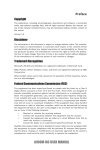
2 The login window is displayed:
Figure 2-1: Login Window
3 Enter the User Name and Password (the default User Name/Password for a user with Admin privileges
are admin/admin).
NOTE!
A user with Admin privileges has full access rights. A user with Operator privileges has limited access
rights, allowing the user to view certain information in some pages and to execute very few actions.
For details see “Operator Accounts” on page 103.
4 Click on the Login button. The management utility Management Status page is displayed.
NOTE!
For prevention of potential configuration conflicts, multiple concurrent logins are not allowed.
At any time, only one user with admin privileges and one user with Operator privileges may be logged
in.
If there is an existing login, and another login (of the same account type) is performed, the earlier
instance would be logged out with the error message: "You are logged in at another place."
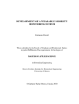
If you forgot your password:
1 Click on the Forgot Password link to open the Reset Password window.
Arena Controller User Manual
3
Chapter 2 - Using the ARENA ControllerAccessing the Web-Based Management Utility
Chapter 2 - Using the ARENA Controller
Accessing the Web-Based Management Utility
Figure 2-2: Reset Password Window
2 Enter your Username and Email address as configured for your account (see “Accounts Tab” on
page 100). For an admin account the user name is admin.
3 You should get an email containing a new password for your account (the old password will become
obsolete).
Arena Controller User Manual
4
Chapter 2 - Using the ARENA ControllerConfiguring Required Parameters in Wireless Network Devices
Chapter 2 - Using the ARENA Controller
Configuring Required Parameters in Wireless Network Devices
2.2
Configuring Required Parameters in Wireless
Network Devices
To verify that the devices can be discovered and properly managed by the ARENA Controller, perform
the following steps (for specific details refer to the applicable sections in the relevant manual):
1 Connect to the device and set the management IP Address (Static or DHCP Client).
2 In the L2TPv3 Settings (for devices that support L2TP), configure the IP address of the ARENA
Controller as the IP address of the Remote Server.
3 Assuming default values are used for relevant parameters in the ARENA Controller, do not change the
configuration of parameters required for discovery and proper management (by default the values of
these parameters in the wireless devices are identical to the default values in the Controller).
Otherwise, make sure that the configuration in the device matches the one of the Controller. This
includes (according to specific device’s capabilities) SNMPv3, SNMPv1/V2C and L2TPv3 parameters.
4 Save and apply settings.
5 For devices that support L2TPv3, verify that there is traffic on the L2TP interface indicating proper
connectivity with the ARENA Controller (you may have to wait a few seconds before there is traffic on
the interface). If there is no traffic, manually power off the AP, wait 10 seconds, and power it on
again. If all relevant parameters are properly configured and there is IP connectivity with the controller
the L2TP tunnel between the controller and the managed device should be established.
INFORMATION
Management of devices that do not support L2TP is very limited: They may be discovered and displayed
on the map, a few general parameter may be displayed and SW upgrade using TFTP or FTP (as
applicable) may be executed. In addition, the system enables a cut-through (in a new browser tab) to the
web-based management of these devices.
In the current release only WBSIac indoor APs support L2TP.
Arena Controller User Manual
5
Chapter 2 - Using the ARENA ControllerUsing the Management Utility
Chapter 2 - Using the ARENA Controller
2.3
Using the Management Utility
Using the Management Utility
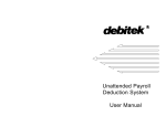
Figure 2-3: ARENA Controller’s Web Page Structure
The management page comprises the following sections:
Menu Bar: The vertical menu bar on the left side of the page enables selection of the main
management function of the page. The background color of the currently selected option is dark
blue.
Tabs Bar: The tabs bar above the work area enables selection of the specific configuration/information
to be presented in the work area. For certain pages second-level tabs may be available. The
background color of the currently selected option is dark blue.
Work Area: Allows viewing relevant information, performing configuration changes and executing
specific actions according to the selected menu and tab options.
General Bar at the top of the page:
»
Use the Network drop-down list to select the network to be managed (when applicable).
»
Click on the Logout icon (
Arena Controller User Manual
) to log out.
6
Chapter 2 - Using the ARENA ControllerUsing the Management Utility
Chapter 2 - Using the ARENA Controller
CAUTION
Using the Management Utility
Do not use any of the following characters in any of the textbox fields in the ARENA Controller web
pages:
space " "
ampersand "&"
plus "+"
double quote """
single quote "'"
backslash "\"
If by mistake you used a text that is not recognized by the system such as the characters specified
above, a warning message would pop-up when attempting to save the configuration. You will
prompted to correct the text by the messages "Please input correct username." (the same message,
using the term username, is used for all textboxes with unrecognized characters).
Arena Controller User Manual
7
Chapter 2 - Using the ARENA ControllerNetwork Page
Chapter 2 - Using the ARENA Controller
2.4
Network Page
Network Page
The Network page comprises two tabs:
General Tab
Create Network Tab
2.4.1
General Tab
The General tab in the Network page enables viewing and configuring the general settings of each of
the managed networks. The network to be managed is selectable from the Network drop-down list at
the top right corner of the page.
Figure 2-4: The Network Page General Tab
The following are the Network Settings parameters which are located in the General tab of the Network
page:
Network Name: This is the read-only name of the network. The Network Name is configurable only
when creating a new network. Every network should have a unique name. A managed device can
belong to one network only.
Managers' Emails: The default email address(es) to which the controller would send alert emails for
events such as when the operational status (up/down) of any of the devices belonging to the network
has been changed. The default is the Email address of the admin account, if defined (see “Admin
Account - Email” on page 101). However, you may define different address(es) for each network. You
Arena Controller User Manual
8
Chapter 2 - Using the ARENA ControllerNetwork Page
Chapter 2 - Using the ARENA Controller
Network Page
can define multiple email addresses separated by comma(s). For example:
[email protected],[email protected]
Time Zone: Select the time zone for the network. This affects all networks in the controller
Location: Use the drop-down list to select the country in which the network is located. When Google
Map is used this country will be displayed in the center of the map in the Management page, Status
tab.
Map Type: Selecting World Map utilizes the Google Map for displaying the locations of the APs
belonging to the network. The Custom Map option allows you to upload an office/any other layout.
INFORMATION
If the Custom Map option is selected, the controls required for uploading a custom map becomes
available below the map section in the Management page, Status tab. For details see “Network Map”
on page 19.
Map Zoom: Applicable only when Map Type is set To World Map (Google Map). The default zoom
level for the displayed map, from 0 (the minimum) to19 (the maximum). The default is set according
to the size of the country selected in the Location drop-down list.
Latitude: Latitude of the center point of the map. The default center point is the center of the
country selected in the Location drop-down list.
Longitude: Longitude of the center point of the map. The default center point is the center of the
country selected in the Location drop-down list.
Environment: Indoor/Outdoor (Outdoor is the default). Select the environment of the network.
Higher ACK timeout is enabled for an Outdoor environment, thus performance for Indoor devices in
the network would be impaired if you use Outdoor settings, and vice versa.
Email Alert: When enabled, alert emails for relevant events will be sent to the email addresses
specified in the Managers’ Emails field.
Network Logo: This is the logo to be displayed on the Login page for device(s) that support hotspot
functionality. Click on the Browse button and navigate to the required location to upload the
required JPEG (.jpg) file.
Default Network: Selected Yes to set the network as the default network to be shown when loging
into the ARENA Controller. If no network is defined as the default one, than the default network will
be the first created network.
Delete Network: Click on the Delete Network link to delete the network and all its settings. A
warning message will be displayed to prevent accidental deletion of a network.
Click the Save Settings button to save the configuration.
Arena Controller User Manual
9
Chapter 2 - Using the ARENA ControllerNetwork Page
Chapter 2 - Using the ARENA Controller
2.4.2
Network Page
Create Network Tab
The Create Network tab in the Network page enables creation of a new network. Each network may
include any number of devices (as long as the total number of devices does not exceed the number
supported by the license). A device may belong only to a single network.
INFORMATION
At least one network must be created. When using the ARENA Controller for the first time, a "There is
no network in your account. Please create one first."message is displayed prompting you to create
at least one network.
Figure 2-5: The Network Page Create Network Tab
The following are the Network Settings parameters which are located in the General tab of the Network
page:
Network Name: This is the name of the network. Every network should have a unique name. A
managed device can belong to one network only.
Managers' Emails: The default email address(es) to which the controller would send alert emails for
events such as when the operational status (up/down) of any of the devices belonging to the network
has been changed. The default is the Email address of the admin account, if defined (see “Admin
Account - Email” on page 101). However, you may define different address(es) for each network. You
can define multiple email addresses separated by comma(s). For example:
[email protected],[email protected].
Time Zone: Select the time zone for the network. This affects all networks in the controller.
Location: Select the country in which the network is located. When Google Map is used this country
will be displayed in the center of the map in the Management page, Status tab.
Map Type: Selecting World Map utilizes the Google Map for displaying the locations of the network
and its’ components. The Custom Map option allows you to upload an office/any other layout.
Arena Controller User Manual
10
Chapter 2 - Using the ARENA ControllerNetwork Page
Chapter 2 - Using the ARENA Controller
INFORMATION
Network Page
If the Custom Map option is selected, the controls required for uploading a custom map becomes
available below the map section in the Management page, Status tab. For details see “Network Map”
on page 19.
Environment: Indoor/Outdoor (Outdoor is the default). Select the environment of the network.
Higher ACK timeout is enabled for an Outdoor environment, thus performance for Indoor devices in
the network would be impaired if you use Outdoor settings, and vice versa.
These parameters (excluding Network Name) may be modified in the General tab of the Network page,
where additional parameters of the network may also be configured.
To create a new network:
1 In the Create Network tab configure the mandatory name for the new network.
2 Modify other parameters as required for the new network.
3 Click on the Create Network button.
4 A success message (“Success! Created network successfully. You can manage your network now”)
will be displayed. Click Ok to continue. The Management page, Status tab for the new network will
be opened.
Arena Controller User Manual
11
Chapter 2 - Using the ARENA ControllerDiscovery Page
Chapter 2 - Using the ARENA Controller
2.5
Discovery Page
Discovery Page
The Discovery page enables discovery of connected devices. It also enables adding newly discovered
devices to a selected network and, if necessary, disabling addition of specific devices to any network by
moving it to the Blocked Devices list.
The Discovery page comprises two tabs:
Discovery Tab
Block Tab
2.5.1
Discovery Tab
Figure 2-6: The Discovery Page Devices Tab
The Devices tab includes the following components:
AP SNMPv3 Settings
AP SNMPv1/v2c Settings
Scan
The Discovered Devices Table
Arena Controller User Manual
12
Chapter 2 - Using the ARENA ControllerDiscovery Page
Chapter 2 - Using the ARENA Controller
2.5.1.1
Discovery Page
AP SNMPv3 Settings
Figure 2-7: Discovery Page, AP SNMPv3 Settings Section
AP SNMPv3 settings define the parameters to be used for searching for and communicating with devices
supporting SNMPv3. The settings in the devices must be identical to the settings configured in the
Controller.
The SNMPv3 Settings parameters are:
Username: The name assigned to the SNMP user. The default is admin.
Auth Password: The password used for authentication using the MD5 protocol. A string of at least 8
characters. The default is password.
Privacy Password: The password used for encrypting the SNMP traffic using the CBC-DES protocol.
A string of at least 8 characters. The default is password.
2.5.1.2
AP SNMPv1/v2c Settings
Figure 2-8: Discovery Page, AP SNMPv1/v2c Settings Section
AP SNMPv1/v2c settings define the parameters to be used for searching for and communicating with
devices supporting either SNMPv1 or SNMPv2c. The settings in the devices must be identical to the
settings configured in the Controller.
The SNMPv1/v2c Settings parameters are:
Read Community: The community string used for read (get) operations. The default is public.
Write Community: The community string used for write (put) operations. The default is private.
Arena Controller User Manual
13
Chapter 2 - Using the ARENA ControllerDiscovery Page
Chapter 2 - Using the ARENA Controller
2.5.1.3
Discovery Page
Scan
Figure 2-9: Discovery Page, Scan Section
To search for devices in a specific IP range using CIDR notation:
1 enter the IP address.
2 Select the required prefix from the drop-down list.
3 Click on the Scan button.
A message indicating the scanning details will be displayed:
Figure 2-10: Discovery Page, Scanning in Progress Message
The estimated time for completion of the scanning process is indicated on the Stop scanning button.
Scanning time is approximately 7 seconds per IP address.
While the scanning is in progress, newly discovered devices are added to the Discovered Devices table in
real-time. If all known new devices that should be discovered are already displayed in the table, the scan
can be stopped by clicking on the Stop scanning button.
NOTE!
2.5.1.4
For devices supporting L2TPv3, the search range may be defined using L2TP addresses, resulting in
faster discovery of devices. For details refer to “Tunnelling Configuration” on page 99. Note that the
L2TP addresses are assigned to devices starting from the first address in the L2TP addresses range,
allowing to minimize the search range (higher prefix) according to the number of relevant devices.
The Discovered Devices Table
The Discovered Devices table lists all devices that were discovered during the last scan process:
Arena Controller User Manual
14
Chapter 2 - Using the ARENA ControllerDiscovery Page
Chapter 2 - Using the ARENA Controller
Discovery Page
Figure 2-11: Discovery Page, Discovered Devices Table
For each discovered device the following details are provided:
Status: The management status of the device:
»
In Network (<network_name)>: The device is already assigned to the indicated network.
»
New: A newly discovered device that is not assigned to any network. For a new device a
checkbox is available on the left side allowing execution of certain actions (see details below).
»
In Block: The device has been moved to the Blocked Devices list (see details below).
Mode: The operation mode of the radio(s) in the device:
»
AP: The radio (in a device supporting a single radio) or both radios (in a device supporting two
radios) operates as an AP.
»
CPE: The radio (in a device supporting a single radio) operates as a CPE (Station).
»
AP|CPE: In a device supporting two radios, one radio operates as an AP and the other radio
operates as a CPE (Station).
Host Name: The device’s name as configured in the device.
IP Address: The IP address of the device (this will be the IP address used for management of the
device, even if the scan was executed using L2TP addresses).
Model: The device’s model.
Version: The running SW version of the device.
Scanning Time: Date and time of device’s discovery.
To add discovered devices to an existing network:
1 In the Network drop-down list (in the right top corner of the page) select the target network.
2 Click to select the checkboxes of the devices you want to add to the target network (you may click on
the checkbox on the left side of the headers row to select all new devices).
Arena Controller User Manual
15
Chapter 2 - Using the ARENA ControllerDiscovery Page
Chapter 2 - Using the ARENA Controller
Discovery Page
3 Click on the Add into current network button.
4 You should get a success message: “Success! The devices that you selected have been added into the
current network. “. Click on the Ok button to return to the Discovery page.
To block discovered devices:
1 Click to select the checkboxes of the devices you want to block (you may click checkbox on the left
side of the headers row to select all new devices).
2 Click on the Block button.
3 You should get a success message: “Success ! The devices that you selected have been blocked.”.
Click on the Ok button to return to the Discovery page.
Blocked devices are added to the Blocked Devices list. In the Discovered Devices list their status becomes
In Block. As long as the status of a device is In Block it cannot be added to any network. For removal of
devices from the Blocked Devices list refer to Block Tab below.
2.5.2
Block Tab
Figure 2-12: Discovery Page Block Tab
The Block tab includes the Blocked Devices table, displaying the details of all blocked device (if any).
To unblock devices:
1 Click to select the checkboxes of the devices you want to unblock (you may click checkbox on the left
side of the headers row to select all blocked devices).
2 Click on the Unblock button.
Arena Controller User Manual
16
Chapter 2 - Using the ARENA ControllerDiscovery Page
Chapter 2 - Using the ARENA Controller
Discovery Page
3 You should get a success message: “Success! The devices that you selected have been unblocked.”.
Click on the Ok button to return to the Discovery page.
Following the next scan of the relevant range the unblocked devices will be marked as New.
Arena Controller User Manual
17
Chapter 2 - Using the ARENA ControllerManagement Page
Chapter 2 - Using the ARENA Controller
2.6
Management Page
Management Page
The Management page comprises the following tabs:
Status Tab
SNMP traps Tab
Export AP(s) Tab
Import AP(s) Tab
Create AP Tab
Upgrade AP(s) Tab
In addition, from the Devices Table in the Status tab you can open the Settings page allowing you to
change the configuration of selected devices. For details see Changing Device(s) Settings.
2.6.1
Status Tab
The Status tab provides a general view of the selected network and the devices it includes. It also
enables various options for viewing more details for a selected device and managing a selectable device
or device groups.
Figure 2-13: Management Page Status Tab
The Status tab includes the following sections:
Network Map
Arena Controller User Manual
18
Chapter 2 - Using the ARENA ControllerManagement Page
Chapter 2 - Using the ARENA Controller
Management Page
Devices Table
From the Devices table you can also open the The Device Information Pop Up Box.
2.6.1.1
Network Map
Figure 2-14: Management Page Status Tab, Network Map Section (Google Map)
The default displayed map will be according to configuration of the relevant parameters in the selected
Network Settings in the Network page (see “General Tab” on page 8).
For a World Map (Google Map), the default location of all devices is in the center of the displayed map
(defined by the Longitude and Latitude settings in the General tab of the Network page). For details on
moving devices to other locations on the map refer to “Position Settings” on page 37.
Device’s icon on the map includes its’ status (see Status parameter in “Devices Table” on page 20). Place
the mouse over the icon to view the device name.
If a the Custom Map option was selected as the Map Type, the following controls will be available below
the Map section:
Figure 2-15: Custom Map Upload
To upload a Custom Map
1 Click on the Browse button and navigate to the required location to upload the pre-prepared JPEG
(.jpg) file.
2 Click on the Upload button. The selected Custom Map will be displayed in the Map section.
Arena Controller User Manual
19
Chapter 2 - Using the ARENA ControllerManagement Page
Chapter 2 - Using the ARENA Controller
2.6.1.2
Management Page
Devices Table
Figure 2-16: Management Page Status Tab, Devices Table Section
This section includes:
Contents of the Devices Table
Wireless Networks Details
Deleting Devices
2.6.1.2.1
Contents of the Devices Table
Above the table summary information for all the devices included in the selected network is displayed.
The displayed information includes total numbers for currently Connected devices, Disconnected devices
and Stations.
To filter the list of displayed devices by device model:
The Model drop-down list (on the right side above the table) enables selection of the model of devices to
be displayed in the table. The available options include All (the default) and the specific models of
devices included in the network.
To sort the table by the values in a selected column:
Click on a column header to sort the table by the content of this column in ascending order. Click again
to sort in descending order.
For each device the following details and operations are available:
Arena Controller User Manual
20
Chapter 2 - Using the ARENA ControllerManagement Page
Chapter 2 - Using the ARENA Controller
Management Page
Status: The management status/mode of the device (used also for the device’s icon on the map):
»
AP: The device is connected and managed. The radio (in a device supporting a single radio) or
both radios (in a device supporting two radios) operates as an AP.
»
CPE: The device is connected and managed. The radio (in a device supporting a single radio)
operates as a CPE (Station).
»
AP|CPE: The device is connected and managed. In a device supporting two radios, one radio
operates as an AP and the other radio operates as a CPE (Station).
»
OFFLINE: The device is considered as disconnected (it was considered as being online but no
information was received from it for more than 2 minutes.
»
WAITING: The device has been discovered but no information was received from it after
discovery. Once it starts sending information it is considered as being online.
»
FAULT: It was considered as being online but no information was received from it for more than
one minute. This is a temporary status: After one additional minute in this status it will be
considered as being offline. If the device will start sending information it will be considered as
being online.
»
Applying (with a red background): A temporary status indicating that changes are being applied
to the settings of the device (see Apply to AP below).
Click on the + sign to on the left side of a device Status to view main details for the VAPs defined in
the device. For details see “Wireless Networks Details” on page 22.
Click on the checkbox on the left side of a device details row to add the device to a Group. See
“Deleting Devices” on page 23 and “Changing Device(s) Settings” on page 34 for details on actions
available for device groups.
Name: The device’s name as configured in the device. Click on a device Name to open the device
information window (see “The Device Information Pop Up Box” on page 23) in the map area.
IP Address: The management IP address of the device. Click on the IP address to open in a new
browser tab a cut-through to the device’s web-based management.
Stations: The number of stations connected to the device.
Uptime: The uptime of the device.
Last Check-in: Elapsed time since the last check-in of the device. If it did not check-in for more than
1 minute, it’s status will change to FAULT. If it did not check-in for more than 2 minutes, it’s status will
change to OFFLINE. If it never checked-in, it status will be WAITING.
Gateway:
Memfree: Available free memory in the device.
Arena Controller User Manual
21
Chapter 2 - Using the ARENA ControllerManagement Page
Chapter 2 - Using the ARENA Controller
Management Page
Model: The model of the device:
»
WBSIac_2V
»
wbsn_2 (WBSn-2400)
»
wbsn_25 (WBSn-2450)
»
ultra_5 (single sector BreezeULTRA B350)
»
ultra_5 (dual sector BreezeULTRA B600)
Hover with the mouse over a Model value (colored green) to open a pop-up box with details of the
supported radio(s).
Version: The running SW version of the device.
Setting: Click on the Settings link (on the right side of the device details row) to open the Settings
page for the device (for devices that do not support this feature a cut-through to the device’s
web-based management will be opened in a new browser tab). You will be requested to wait a few
seconds to allow the controller to get relevant settings from the device. See more details in
“Changing Device(s) Settings” on page 34.
Delete: Click on the Delete link to remove the device from the network. A warning message will be
displayed requesting you to either confirm or cancel the action.
Apply to AP: After making changes to device(s) settings, a blinking Apply to AP message is
displayed on the right side of each relevant device. Click on the message to apply the changes to the
device. The device status (in the table and on the map) will change temporarily to Applying.
The following buttons are available below the table to support operations on a group of APs:
Group Edit button: refer to “Changing Device(s) Settings” on page 34 for details on functionality of
this button.
Group Delete button: Refer to “Deleting Devices” on page 23 for details on functionality of this
button.
The table is updated every 15 seconds.
2.6.1.2.2
Wireless Networks Details
To view main details of the wireless networks (VAPs for WBSn and WBSIac/Sectors for BreezeULTRA)
defined in a specific device, click on the + sign on the left side of the device Status (you can click in the
+ sign on the left side of the headers row to open the details for all devices). The sign will be changed to
a - sign.
Arena Controller User Manual
22
Chapter 2 - Using the ARENA ControllerManagement Page
Chapter 2 - Using the ARENA Controller
Management Page
Figure 2-17: VAPs/Sectors Details
The details available for each VAP/Sector are:
Name: The wireless network identification (a greyed-out background for a disabled VAP/Sector).
MAC Address: The MAC address(es) of the radio(s) used by the wireless network.
SSID: The SSID identifying the wireless network.
Profile: The profile(s) (IEE802.11 standards) supported by the radio(s).
Channel: The current operating channel(s)/frequency of the radio(s).
Encryption: The Security Mode used for traffic on the wireless network.
Bit Rate: The total bit rate(s) that can be supported by the radio(s).
Stations: The total number of stations connected to the wireless network.
Click on the - sign to hide the wireless networks details.
2.6.1.2.3
Deleting Devices
To delete a single device:
Click on the Delete link (on the right side of the device details row) of the selected device. A warning
message will be displayed requesting you to either confirm or cancel the action.
To delete multiple device:
1 Click on the checkbox on the left side of a device details row to add the device to a Group. You may
click on the checkbox on the left side of the headers row to select all devices.
2 Click on the Group Delete button to remove all selected devices from the network. A warning
message will be displayed requesting you to either confirm or cancel the action.
2.6.1.3
The Device Information Pop Up Box
Click on a device Name in the Devices table to open the Device Information pop up box in the map area:
Arena Controller User Manual
23
Chapter 2 - Using the ARENA ControllerManagement Page
Chapter 2 - Using the ARENA Controller
Management Page
Figure 2-18: The Device Information Window, General Tab)
The Device Information pop up box includes the following tabs:
General Tab
Radios Tab
SSIDs Tab
Neighbors Tab
Stations Tab
Logs Tab
2.6.1.3.1
General Tab
The details provided in the General tab are identical to those shown for the device in the Devices Table
(see “Contents of the Devices Table” on page 20).
2.6.1.3.2
Radios Tab
Figure 2-19: The Device Information Window, Radios Tab
The Radio tab provides the following details for each radio card:
Model(Chipset): The type of chipset used in the card.
Channel: The current operating channel.
Bit Rate: The total bit rate supported by the radio.
Arena Controller User Manual
24
Chapter 2 - Using the ARENA ControllerManagement Page
Chapter 2 - Using the ARENA Controller
Management Page
ACK Timeout: The method of setting the ACK Timeout parameter (Manual or Automatic).
ACK Timeout Value: The value setting of the ACK Timeout parameter.
2.6.1.3.3
SSIDs Tab
Figure 2-20: The Device Information Window, SSIDs Tab
The SSIDs tab provides the following details for each configured VAP:
SSID: The SSID identifying the VAP.
Profile: The profiles (IEE802.11 standards) supported by the radio(s).
Channel: The current operating channel(s) of the radio(s).
Encryption: The Security Mode used for traffic on the VAP.
TX Rate/RX Rate: The total Tx and Rx bit rate(s) that can be supported by the radio(s).
2.6.1.3.4
Neighbors Tab
Figure 2-21: The Device Information Window, Neighbors Tab
The Neighbors tab is applicable only for devices belonging to a mesh network, providing the following
details for each configured neighbor (see ....).
Status:
Name: The name of the neighbor device.
Arena Controller User Manual
25
Chapter 2 - Using the ARENA ControllerManagement Page
Chapter 2 - Using the ARENA Controller
Management Page
MAC Address: The MAC address of the neighbor device
IP Address: The IP address of the neighbor device
2.6.1.3.5
Stations Tab
Figure 2-22: The Device Information Window, Stations Tab
The Stations tab provides the following details for each connected station:
Host: The name of the station.
IP Address: The IP address of the station.
MAC Address: The MAC address of the station.
Network: The SSID identifying the VAP to which the station is connected.
Signal: The total strength (in dBm) of the signal received from the station.
Signal/Chains: The strength of the signal received from the station per chain (the value of -95 dBm is
taken to mean "no antenna").
TX Rate: The transmit bit rate of the station.
RX Rate: The receive bit rate of the station.
TX-CCQ: The transmission quality in % (a higher percentage means a better wireless connection
quality).
The list of stations is updated every 1 minute.
Arena Controller User Manual
26
Chapter 2 - Using the ARENA ControllerManagement Page
Chapter 2 - Using the ARENA Controller
2.6.1.3.6
Management Page
Logs Tab
Figure 2-23: The Device Information Window, Logs Tab
The Logs tab displayed the recorded activity of stations that were connected to the AP during the last
hour:
Host: The name of the station.
IP Address: The IP address of the station.
MAC Address: The MAC address of the station.
Brand: The brand (manufacturer) of the station.
Network: The SSID identifying the VAP to which the station is connected.
Signal: The total strength (in dBm) of the signal received from the station.
Signal/Chains: The strength of the signal received from the station per chain (the value of -95 dBm is
taken to mean "no antenna").
TX Rate: The average transmit bit rate of the station during the recorded session.
RX Rate: The average receive bit rate of the station during the recorded session.
Upload(MB): The total amount of data uploaded from the device during the recorded session.
Download(MB): The total amount of data downloaded to the device during the recorded session.
Total(MB): The total amount of data uploaded/downloaded from/to the device during the recorded
session.
The information is updated every 15 seconds.
2.6.2
SNMP traps Tab
Figure 2-24: The SNMP traps Tab
The SNMP traps tab displays the traps received from APs belonging to the selected network (provided
they are configured to send traps to the controller).
Arena Controller User Manual
27
Chapter 2 - Using the ARENA ControllerManagement Page
Chapter 2 - Using the ARENA Controller
Management Page
Click on the Download button (at the bottom of the page) to save the information as a text file.
2.6.3
Export AP(s) Tab
The Export AP(s) tab allows saving certain details of the devices belonging to the selected network in a
comma separated values (.csv) file. This file can be used at a later time for importing these devices to the
same or another network (see “Import AP(s) Tab” on page 29).
Figure 2-25: The Export AP(s) Tab
The file includes the following parameters for each device:
Device Name
IP Address
MAC Address
Device Model
Latitude
Longitude
SNMP V3 Username
SNMP V3 Auth Password
SNMP V3 Privacy Password
SNMP V1 Write Community
When importing this file in the future, these parameters will be used for discovering the devices and
positioning them in the configured coordinates.
To export devices to a .csv file:
Arena Controller User Manual
28
Chapter 2 - Using the ARENA ControllerManagement Page
Chapter 2 - Using the ARENA Controller
Management Page
1 Enter a name for the file in the Filename text box.
2 Click on the Start Export button to save the CSV file. The date will be added as a suffix to the file
name.
3 The file will be saved in the Downloads directory.
2.6.4
Import AP(s) Tab
Figure 2-26: Import AP(s) Tab
The Import AP(s) feature can be used when there is a need to restore the list of devices in a network or
to move the devices from one network to another one (in the same or another controller).
NOTE!
A device may belong to one network only. If necessary, verify that relevant devices are deleted from the
original network before importing them (to either the same or another network).
To import devices to the selected network:
1 Make sure that the required file is available on your PC. It should be a file prepared previously using
the Export AP(s) feature.
2 Click on the Browse button and navigate to the required location to upload the CSV file.
3 Click on the Start Import button. Appropriate messages indicating the progress of the process and
the results will be displayed.
4 The imported devices will be added to the network. It may take a few minutes before all verified
details and status are properly displayed in the Status tab.
Arena Controller User Manual
29
Chapter 2 - Using the ARENA ControllerManagement Page
Chapter 2 - Using the ARENA Controller
2.6.5
Management Page
Create AP Tab
The Create AP feature enables creating a device’s entity even before the device is connected to the
network, to be automatically added to the network with a WAITING status to be updated once the
device can be reached by the controller.
Figure 2-27: Create AP Tab
To create a new AP:
1 Configure the following identification parameters in the Hardware section:
»
Name: The Name of the device.
»
MAC Address: The MAC address of the device.
»
IP Address: The management IP address of the device.
»
Model: Select the device’s model from the drop-down list.
Arena Controller User Manual
30
Chapter 2 - Using the ARENA ControllerManagement Page
Chapter 2 - Using the ARENA Controller
Management Page
2 Configure the following SNMP parameters in the SNMP Settings (Arena to AP) section (if different
from the defaults):
»
Username: Applicable only for devices supporting SNMPv3. The name assigned to the SNMP
user. The default is admin.
»
Auth Password: Applicable only for devices supporting SNMPv3. The password used for
authentication using the MD5 protocol. A string of at least 8 characters. The default is password.
»
Privacy Password: Applicable only for devices supporting SNMPv3. The password used for
encrypting the SNMP traffic using the CBC-DES protocol. A string of at least 8 characters. The
default is password.
»
Write Community: Applicable only for devices supporting SNMPv1/v2c. The write (put)
community string that can also be used for read (get) operations. The default is private
These settings must match the SNMP settings in the device.
3 If required, modify the position of the device:
The read only settings in the Position section show the coordinates (Latitude and Longitude) that will
be used for positioning the device on the map, and the current Zoom level of the map.
The default position coordinates is the location selected for the entire network in the Network page
(see “General Tab” on page 8).
To change device’s position on the map:
a In the map area, change the zoom level as required (the read-only Map Zoom parameter in the
Position section will changed accordingly).
b Click and drag the device icon to the required location for the device (the read-only coordinates in
the Position section will changed accordingly).
4 Click on the Create AP button to create an entry for the new device.
The created device will be added to the network with a WAITING status. If all parameters are properly
configured, the status will be updated once the device is connected and starts sending information to
the controller.
Arena Controller User Manual
31
Chapter 2 - Using the ARENA ControllerManagement Page
Chapter 2 - Using the ARENA Controller
2.6.6
Management Page
Upgrade AP(s) Tab
Figure 2-28: Upgrade AP(s) Tab
The ARENA Controller lets you upgrade multiple selected devices concurrently.
Depending on the type of devices to be upgraded, either FTP or TFTP is used for the upgrade process
(TFTP client in the management PC should be used for BreezeULTRA, an external FTP server should be
used for WBSn and WBSIac units).
Prior to starting the upgrade process, the required firmware file should be available on the FTP
server/management station.
The Upgrade AP(s) tab includes the following sections:
Devices Table
FTP Settings
TFTP Settings
2.6.6.1
Devices Table
The devices table includes the following details for each of the selected network’s devices:
Status: The status of the device (for details see “Devices Table” on page 20).
Name: The name of the device.
IP Address: The management IP address of the device.
Model: The hardware model of the device.
Version: The current running SW version in the device.
A selection checkbox is available on the left side of each entry.
Arena Controller User Manual
32
Chapter 2 - Using the ARENA ControllerManagement Page
Chapter 2 - Using the ARENA Controller
2.6.6.2
Management Page
FTP Settings
The FTP Settings section includes the following parameters required for upgrading firmware using FTP:
FTP IP: The IP address of the FTP server.
FTP PORT: The port number used for FTP. The default is 21.
FTP Username: The user name to be used for FTP transactions.
FTP Password: The password to be used for FTP transactions.
FTP File Type: The FTP file type. The default is 1.
FTP File Name: The name of the file in the FTP server.
2.6.6.3
TFTP Settings
The TFTP Settings section includes the TFTP File Name. Click on the Browser button and navigate to
the required location to upload the upgrade file.
To upgrade device(s) firmware:
1 Enter the necessary FTP/TFTP settings.
2 Select the devices to be upgraded (you may select all devices by clicking on the checkbox in the
headers row). All selected devices must be of the same Model. Only devices whose Status is online
should be selected for an upgrade process.
3 Click on the Upgrade button below the table.
4 The AP Upgrade page will be opened:
Figure 2-29: AP Upgrade Page
5 The AP Upgrade page includes a table with the details of all APs selected for upgrade. In addition, it
provides the Response Status for each entry. If there is a problem such as incomplete or wrong
FTP/TFTP settings or no connectivity from the target device to the FTP server, the response status
(colored red) will indicate the problem. Otherwise:
»
For BreezeULTRA and WBSn units, the response status should be “Ready to upgrade” and an
Upgrade button will become available on the right side of the entry.
»
For WBSIac units, the response status should be “Ready to download from FTP server” and a
Download button will become available on the right side of the entry.
Arena Controller User Manual
33
Chapter 2 - Using the ARENA ControllerManagement Page
Chapter 2 - Using the ARENA Controller
Management Page
6 Click on each Upgrade/Download button to initiate the upgrade process. The ARENA Controller
sends the applicable SNMP commands to each device for downloading the firmware as it’s shadow
version.
7 Once each device has downloaded the firmware, the Upgrade button appears for the device.
8 Click on the Upgrade button to complete the upgrade process and start running the device using the
new version as it’s main version.
9 The Status Response field will indicate whether the firmware upgrade was successful or unsuccessful.
When there are any problems in the upgrade process, Upgrade issue! is displayed in red text. This is
because the AP did not send the upgrade success message to the ARENA Controller. Hover your mouse
over the red text to see the details in the infotip.
If the upgrade was carried out successfully, Upgrade success! is displayed in green text.
2.6.7
Changing Device(s) Settings
NOTE!
In the current release, editing device(s) configuration is applicable only for WBSIac units.
To open the Settings page for a single device:
Click on the Settings link (on the right side of the device details row) of the selected device to open the
Settings page for a single device. You may have to wait a few seconds to allow the controller to get
relevant settings from the device.
NOTE!
The Setting page for a single device can also be opened by selecting a single device and clicking on the
Group Edit button (see details below).
To open the Settings page for multiple device:
1 Click on the checkbox on the left side of a device details row to add the device to a Group. You may
click on the checkbox on the left side of the headers row to select all devices.
NOTE!
To properly support Group Edit functionality for multiple devices all selected devices must be of the
same hardware model.
2 Click on the Group Edit button to open the Group Edit device selection page:
Arena Controller User Manual
34
Chapter 2 - Using the ARENA ControllerManagement Page
Chapter 2 - Using the ARENA Controller
Management Page
Figure 2-30: Group Edit Device Selection
3 In the According to drop-down list select the device whose setting will be used as the basis for
editing.
4 Click on the Group Edit button to open the Settings page for multiple devices (see details in
“Changing Device(s) Settings” on page 34).
In a group editing mode, changes will be applied to all selected devices.
The Settings tabs are the following:
General Settings Tab (available only in Setting page for a single device)
Radio Settings Tab
Advanced Settings Tab
Access Settings Tab
Refer to the relevant device manual for more details on the parameters available in the Settings tabs.
NOTE!
If you make any changes, remember to click the Save Settings button at the bottom right corner
before switching to another Settings tab or exiting editing mode.
The changes are saved in the database of the controller. After making changes to device(s) settings,
click on the Management option in the vertical menu bar to view the devices table. A blinking Apply
to AP message is displayed on the right side of each relevant device. Click on the message to apply the
changes to the device. The device status (in the table and on the map) will change temporarily to
Applying.
2.6.7.1
General Settings Tab
NOTE!
The General Settings tabs is available only when editing a single device.
Arena Controller User Manual
35
Chapter 2 - Using the ARENA ControllerManagement Page
Chapter 2 - Using the ARENA Controller
Management Page
Figure 2-31: General Settings Tab
The General Settings tab includes the following sections:
AP Settings
AP SNMPv3 Settings
Position Settings
2.6.7.1.1
AP Settings
The AP Settings section includes a single parameter:
Name: The Name of the device.
2.6.7.1.2
AP SNMPv3 Settings
AP SNMPv3 settings define the parameters to be used for searching for and communicating with devices
supporting SNMPv3.
The SNMPv3 Settings parameters are:
Username: The name assigned to the SNMP user. The default is admin.
Auth Password: The password used for authentication using the MD5 protocol. A string of at least 8
characters. The default is password.
Privacy Password: The password used for encrypting the SNMP traffic using the CBC-DES protocol.
A string of at least 8 characters. The default is password.
These settings could be different for different devices. They must match the SNMPv3 settings in the
device. Due to security reasons, these settings cannot be transferred from the ARENA Controller to the
devices. The same values should be configured on both the ARENA Controller and the device.
Arena Controller User Manual
36
Chapter 2 - Using the ARENA ControllerManagement Page
Chapter 2 - Using the ARENA Controller
2.6.7.1.3
Management Page
Position Settings
The Position read only settings show the current coordinates (Latitude and Longitude) for the device
location on the map and the current Zoom level.
The default location on the general map for all devices is the location selected for the entire network in
the Network page (see “General Tab” on page 8).
To change device location on the map:
1 In the map area, change the zoom level as required (the read-only Map Zoom parameter in the
Position section will changed accordingly).
2 Click and drag the device icon to the required location for the device (the read-only coordinates in the
Position section will changed accordingly).
3 Click on the Save button to save the new device coordinates.
The change will affect the location of the device icon on the general network map.
2.6.7.2
Radio Settings Tab
The Radio Settings tab includes the following second-level tabs:
Main
Radio Tab(s)
2.6.7.2.1
Main
Figure 2-32: Radio Settings, Main Tab
The Main second-level tab includes the following parameters for each of the radios available in the
device(s).
Arena Controller User Manual
37
Chapter 2 - Using the ARENA ControllerManagement Page
Chapter 2 - Using the ARENA Controller
Management Page
Enable/Disable the radio.
Mesh: Disable (the default) or Enable. Refer to .... for details on configuring mesh networks.
SSID1 through SSID4: Up to 4 SSIDs (VAPs) can be configured for each radio. The available options
for each SSID are On (enable), Off (disable) and NA (not available).
Profile: The wireless IEEE standard(s) used. For the 2.4 GHz band only the 802.11g+n (meaning
802.11g+802.11n) option is applicable. For the 5 GHz band available options are 802.11ac and
802.11a+n (meaning 802.11ac+802.11n).
Country: Select the country in which the device operates to ensure that the applicable regulatory
requirements are enforced. Local regulations affects parameters such as available channels and
maximum Tx power.
Channel: Select Auto or a specific channel. For an AP, use the Auto option to select the channel with
the least interference. For a Station, always use the Auto option to automatically select the same
channel as its AP.
Spectrum Width: The available options for the channel bandwidth are:
»
20 MHz
»
20/40 MHz, allows both 20 and 40 MHz bands to be used (depending on the connected device).
»
20/40/80 MHz: Available only for the 802.11ac wireless standard, allowing bandwidths of 20, 40,
and 80 MHz.
Transmit Power: The total transmit power at the antennas ports. Select a specific value or Max. The
maximum allowed value depends on applicable regulatory limitations and, in certain cases, the
operating channel.
Auto-ACK Timeout: Auto or Disable. Select auto to automatically adjust the ACK-timeout according
to the calculated distance of each station from the AP. If the AP serves multiple stations located at
different distances from the AP, it is recommended to disable this option to prevent the ACK timeout
from fluctuating widely. If set to Disable, ACK timeout is determined by the Distance parameter.
Distance (m): Available only if Auto-ACK Timeout is disabled. The maximum distance of any station
from the AP. The minimum is 300 meters. The maximum is 12000 (for a 80MHz bandwidth) / 24000
(for a 40MHz bandwidth) / 48000 (for a 20MHz bandwidth). This value should be set to slightly more
than the physical distance between the AP and the farthest station.
2.6.7.2.2
Radio Tab(s)
For each SSID configured for the relevant radio, the following sub-tabs are available:
General Setup
Wireless Security
MAC Filter
Advanced Settings
Arena Controller User Manual
38
Chapter 2 - Using the ARENA ControllerManagement Page
Chapter 2 - Using the ARENA Controller
Management Page
The tabs and their options are listed in the following sections.
2.6.7.2.2.1
General Setup
Figure 2-33: Radio Settings, Radio General Setup Tab
The General Setup sub-tab includes the following parameters:
Mode: The operation mode of the VAP. Available options are:
NOTE!
»
Access Point
»
Access Point (WDS)
»
Station
»
Station (WDS)
Setting more than 1 station is not supported because there can only be one default
gateway. Both radios cannot be in Station or Station (WDS) mode at the same time.
ESSID: The name or extended service set identifier (ESSID) of the wireless network. A string of up to
32 characters. In AP mode, it is the name of the network as advertised in the beacon messages. In
Station mode, it is the network name that the can station associate with.
Guard Interval: Short (the default) or Long. Guard intervals are used to ensure that distinct
transmissions do not interfere with one another. Data rate is improved in both downlink and uplink if
both AP and station use Short Guard Interval.
Arena Controller User Manual
39
Chapter 2 - Using the ARENA ControllerManagement Page
Chapter 2 - Using the ARENA Controller
Management Page
Data Rate (Mbps): Selects the maximum data rate or the modulation and coding scheme (MCS). In
Auto mode (the default) the MCS and data rates are adjusted automatically depending on the
wireless channel conditions. The available options are:
»
Auto (default)
»
6, 9, 12, 18, 24, 36, 48, 54 Mbps (applicable for 802.11g)
»
MCS 0 - 15 (applicable for 802.11n and 802.11ac)
Hide SSID: Yes or No (the default). Select Yes to hide the network name (ESSID) from being
broadcasted publicly (applicable only for AP mode). Hiding the SSID can decrease the amount of
stations that may try connecting to the wireless network. If Hotspot service is enabled, SSID should
not be hidden.
2.6.7.2.2.2
Wireless Security
Figure 2-34: Radio Settings, Radio Wireless Security Tab
The Wireless Security sub-tab includes the following parameters:
Arena Controller User Manual
40
Chapter 2 - Using the ARENA ControllerManagement Page
Chapter 2 - Using the ARENA Controller
Management Page
Wireless Security: The selected Wireless Security option and relevant parameters define the
methods to be used for authentication of client stations and for protecting the information
transferred over the wireless link. The available options are:
»
No Encryption
»
WEP-Open
»
WEP-Shared
»
WPA-PSK
»
WPA2-PSK
»
WPA/WPA2-PSK
»
WPA/EAP
»
WPA2/EAP
No Encryption: No authentication, no encryption of over the air information. This is the default
mode that should typically be used for testing purposes or for enabling any client to connect with the
AP (e.g. to support Hotspot services).
WEP: Wired Equivalent Privacy (WEP) is the oldest and least secure encryption algorithm. In 2004 the
IEEE declared that both WEP-40 and WEP-104 "have been deprecated as they fail to meet their
security goals”. Stronger encryption using WPA or WPA2 should be used where possible.
The same shared WEP key must be configured in both side of the wireless link, and is used for both
authentication and encryption of over the air traffic.
For the WEP Open System and WEP Shared Key encryptions, you can specify up to 4 keys and only 1
would be used at a time. The following parameters are available:
»
Used Key Slot: Chooses between Key #1 to Key #4.
»
Key #1: Specifies a string of characters to be used as the password. It may consist of 5 ASCII
characters or 10 HEX characters, implying a 64-bit WEP key length (WEP 40). Otherwise, it may
consist of 13 ASCII or 26 HEX characters, implying a 128-bit key length (WEP 104).
»
NOTE!
Key #2, Key #3, and Key #4: Similar to Key #1.
Valid HEX characters are numbers 0-9 and letters A-F, case insensitive. Valid ASCII characters are
numbers and the letters of the English alphabet, case sensitive.
WPA or WPA2 with PSK: WPA (Wi-Fi Protected Access) became available in 2003 and was intended
as an intermediate measure in anticipation of the availability of the more secure and complex WPA2.
WPA is a more powerful security technology for Wi-Fi networks than WEP. It provides strong data
protection by using encryption as well as better access control and user authentication. TKIP
(Temporal Key Integrity Protocol) is used for data encryption. TKIP is no longer considered secure and
was deprecated in the 2012 revision of the 802.11 standard.
Arena Controller User Manual
41
Chapter 2 - Using the ARENA ControllerManagement Page
Chapter 2 - Using the ARENA Controller
Management Page
WPA has been replaced by WPA2 using the much stronger AES-based security. The WPA options are
available for supporting some client devices that do not support WPA2 with AES encryption. These
options are no longer supported for client using the IEEE 802.11n standard.
For WPA-PSK, WPA2-PSK, WPA-PSK/WPA2-PSK Mixed Mode encryptions, we have the following
options.
»
Cipher: Can be set to Auto, CCMP (AES), or TKIP and CCMP (AES). The Counter Mode Cipher
Block Chaining Message Authentication Code Protocol (CCMP) is based on the Advanced
Encryption Standard (AES) and is the most secure protocol.
»
Key: The pre-shared key (PSK) is the password for the wireless network. This may consist of 8 to
63 printable ASCII characters.
WPA or WPA2 with EAP: The Extensible Authentication Protocol (EAP) is encapsulated by the IEEE
802.1X authentication method. IEEE 802.1X is equivalent to EAP over LAN or WLAN. Enterprise
networks commonly use this authentication method.
Required parameter depend on the operation mode of the device:
1 AP Mode
»
Cipher: The options are Auto, CCMP (AES), TKIP and CCMP (AES).
»
Radius-Authentication-Server: The IP address of the RADIUS authentication server.
»
Radius-Authentication-Port: The port number for the RADIUS authentication server. Normally,
the port number is 1812.
»
Radius-Authentication-Secret: The password for authentication transaction.
»
Radius-Accounting-Server: The IP address of the RADIUS accounting server.
»
Radius-Accounting-Port: The port number for the RADIUS accounting server. Normally, the port
number is 1813.
»
Radius-Accounting-Secret: The password for accounting transaction.
»
NAS ID: Specifies the identity of the network access server (NAS).
2 Station Mode
»
Cipher: The options are Auto, CCMP (AES), TKIP and CCMP (AES).
»
EAP-Method: The authentication protocol can be set to Transport Layer Security (TLS), Tunneled
TLS (TTLS), or Protected EAP (PEAP).
»
Path to CA-Certificate: Selects the file for the CA certificate.
»
Path to Client-Certificate: Selects the file for the client certificate.
Arena Controller User Manual
42
Chapter 2 - Using the ARENA ControllerManagement Page
Chapter 2 - Using the ARENA Controller
NOTE!
Management Page
The certificate authority (CA) is a trusted third party that issues digital certificates. In a public key
infrastructure scheme, a digital certificate certifies the ownership of a public key by the named subject
of the certificate.
Options for TLS as the EAP method:
»
Path to Private Key: Selects the file for the private key.
»
Password of Private Key: The password for the private key.
Options for TTLS or PEAP as the EAP method:
»
Authentication: Selects the authentication method used by the AP, e.g., PAP, CHAP, MSCHAP, or
MSCHAPV2.
»
Identity: Sets the identity used by the supplicant for EAP authentication.
»
Password: Sets the password used by the supplicant for EAP authentication.
Arena Controller User Manual
43
Chapter 2 - Using the ARENA ControllerManagement Page
Chapter 2 - Using the ARENA Controller
2.6.7.2.2.3
Management Page
MAC Filter
The MAC Filter sub-tab is applicable only for AP Mode.
Figure 2-35: Radio Settings, Radio MAC Filter Tab
MAC ACL: The options are Disable (the default), Allow and Deny.
A MAC access list is a group of client MAC addresses that can be either permitted or denied access to
the network.
If an Allow ACL is defined, only stations with a MAC address included in the ACL are allowed to
associate to the wireless network, and an association attempt by any stations whose MAC address is not
included will be rejected.
If a Deny ACL is defined, an association attempt by any stations whose MAC address is included in the
ACL will be rejected. All stations with a MAC address that is not included in the ACL are allowed to
associate to the network.
If either Allow or Deny option is selected, you can enter a list of MAC addresses (separated by comma)
that will be included in the Allow/Deny list.
Arena Controller User Manual
44
Chapter 2 - Using the ARENA ControllerManagement Page
Chapter 2 - Using the ARENA Controller
2.6.7.2.2.4
Management Page
Advanced Settings
Figure 2-36: Radio Settings, Radio Advanced Settings Tab
The parameters available in the Advanced Settings sub-tab are:
RTS Threshold: Sets the threshold for the packet size (in octets) above which the request to send
(RTS) mechanism is used. The default in the device is 2346 octets, which means that practically RTS
will never be used. There is a trade-off to consider when setting this parameter. On the one hand,
using a small value causes RTS packets to be sent more often, consuming more of the available
bandwidth, and therefore reducing the throughput of the network. On the other hand, when more
RTS packets are sent, the system recovers faster from interference or collisions. This is useful in a
heavily loaded network, or a wireless network with high interference level. The default in the
controller is blank, meaning no change.
Station Isolation: Applicable only for AP mode. When Station Isolation is disabled (the default),
wireless clients can communicate with one another normally by sending traffic through the AP. When
Station Isolation is enabled, the AP blocks communication between wireless clients on the same AP.
Maximum Stations: Applicable only for AP mode. The maximum number of stations that can
associate with the AP (the default in the AP is 127). The default in the controller is blank, meaning no
change.
Minimum Stations RSSI: Applicable only for AP mode. The minimum received signal strength
indicator required for allowing a station to be associated. At value of 0 (the default in the AP) means
that the AP would allow a station to associate independent of its RSSI. The default in the controller is
blank, meaning no change.
802.11n/802.11ac Only: Applicable only for AP mode. When enabled, the device can use only the
IEEE802.11n or IEEE802.11ac standard. The default is Disable.
HT20/HT40 Coexistence: Allows the network to use both 20 MHz and 40 MHz bandwidths.
Required on AP side primarily to support co-existence. The station can also send intolerant bit status
to AP to signal the use of a 20 MHz channel. The station follows the AP's channel bonding and
Arena Controller User Manual
45
Chapter 2 - Using the ARENA ControllerManagement Page
Chapter 2 - Using the ARENA Controller
Management Page
channel switching HT 20/40 mechanism. Disabling this parameter (the default) forces the use of 40
MHz bandwidth/channel bonding, and results in a high data rate.
WMM: WMM (Wi-Fi Multi Media), as defined by the IEEE 802.11e standard, provides basic quality of
service (QoS) features to IEEE 802.11 wireless networks. WMM enables the classification of the
network traffic into 4 main types in decreasing order of priority:
»
Voice (the highest priority)
»
Video
»
Best Effort (data from applications or devices that do not support QoS)
»
Background (the lowest priority, used for file downloads, print jobs and other traffic that does not
suffer from increased latency)
Higher priority traffic has a higher transmission opportunity and would have to wait less time to
transmit. As a result, an existing video stream would not be interrupted by additional background
processes.
NOTE!
2.6.7.3
In order to support end-to-end QoS, both ends of the network should support the same QoS priority
marking.
Advanced Settings Tab
Figure 2-37: Advanced Settings Tab
The Advanced Settings tab includes the following parameters:
Set SSH Passwords of root user: You may enter a new password for the "root" user of the ARENA
Controller AP's Linux shell.
Web:
Arena Controller User Manual
46
Chapter 2 - Using the ARENA ControllerManagement Page
Chapter 2 - Using the ARENA Controller
Management Page
Failover AP Controller: Future feature)
2.6.7.4
Access Settings Tab
The Access Settings tab enables configuring the AP to operate as a hotspot, offering public access to the
internet.
NOTE!
Before configuring an AP to provide hotspot service, you should connect to the device and configure
the LAN, Wifi, and WAN settings, then test it before enabling the hotspot settings using the ARENA
controller. For details refer to the Hotspot section in the relevant device manual.
The Access Settings tab includes the following second-level tabs:
General Settings
Network Configuration
Radius Configuration
2.6.7.4.1
General Settings
Figure 2-38: Access Settings, General Settings Tab
The General Setting second-level tab includes the following parameters:
Enable Hotspot: Enable or Disable (the default) Hotspot service.
Arena Controller User Manual
47
Chapter 2 - Using the ARENA ControllerManagement Page
Chapter 2 - Using the ARENA Controller
Management Page
Hotspot Mode: Selects the required mode for providing hotspot service. The available options are:
»
User Name + Password (Radius Required)
»
Agreement (Radius Required)
»
Agreement (Radius not Required)
»
Password (Radius Required)
»
Password (Radius not Required)
Password: Available only if selected mode is Password (Radius not Required). The password to be
used for allowing access to the Internet.
Login Page Title: The title to be shown on the Login Page.
Idle Timeout: The timeout in seconds before disconnecting non-active users (unless otherwise set by
the RADIUS server). A value of 0 means unlimited time. The default is 300 seconds.
2.6.7.4.2
Network Configuration
Figure 2-39: Access Settings, Network Configuration Tab
Auto Config: Do not change the default configuration (Yes) to automatically configure the network
parameters.
Arena Controller User Manual
48
Chapter 2 - Using the ARENA ControllerManagement Page
Chapter 2 - Using the ARENA Controller
2.6.7.4.3
Management Page
Radius Configuration
Figure 2-40: Access Settings, Radius Configuration Tab
The Radius Configuration second-level tab includes the following parameters:
Radius Server 1: The IP address of the primary RADIUS server. The IP address of the ARENA
Controller can be used.
Radius Server 2: The IP address of the secondary RADIUS server.
Radius Secret: The Radius shared secret for both servers. The secret should be changed from its
default value (test) in order not to compromise security.
UAM Server: URL of the UAM (Universal Access Method) web server to use for authenticating
clients.
UAM Secret: Shared secret between the UAM server and the controller. This secret should be set in
order not to compromise security (default: leave as blank).
Walled Garden (Domain): A comma separated list of resources the client can access without first
authenticating. Each entry in the list is a domain name. Do not put www in the domain name. For
example: google.com is a valid domain name, www.google.com is not acceptable.
Walled Garden (IP Address): A comma separated list of resources the client can access without first
authenticating. Each entry in the list is an IP Address. The list must include the IP addresses of the AP’s
web page and the ARENA Controller's web page.
Arena Controller User Manual
49
Chapter 2 - Using the ARENA ControllerUsers Page
Chapter 2 - Using the ARENA Controller
2.7
Users Page
Users Page
The Users page includes the following tabs:
Stations Tab
Logs Tab
Clear users Tab
2.7.1
Stations Tab
Figure 2-41: The Users Page, Stations Tab
The Stations tab provides the following details for each of the currently connected stations:
Host: The name of the station.
IP Address: The IP address of the station.
MAC Address: The MAC address of the station.
Network: The SSID identifying the VAP to which the station is connected.
Signal: The total strength (in dBm) of the signal received from the station.
Signal/Chains: The strength of the signal received from the station per chain (the value of -95 dBm is
taken to mean "no antenna").
TX Rate: The transmit bit rate of the station.
RX Rate: The receive bit rate of the station.
TX-CCQ: The transmission quality in % (a higher percentage means a better wireless connection
quality).
Arena Controller User Manual
50
Chapter 2 - Using the ARENA ControllerUsers Page
Chapter 2 - Using the ARENA Controller
2.7.2
Users Page
Logs Tab
Figure 2-42: The Users Page, Logs Tab
The Logs tab displays the recorded activity for a selectable time period of all devices that were connected
to all managed APs. The parameters displayed includes the following:
Status: The current connection status. ONLINE or OFFLINE.
Mode: The operation mode of the AP (Bridge or Router).
AP’s Name: The AP to which the device is/was connected.
VAP: The VAP to which the device is/was connected.
SSID: The SSID of the VAP to which the device is/was connected.
Host IP Address: The IP address of the end user device.
MAC address: MAC address of the end user device.
Brand: The brand (manufacturer) of the end user device.
Upload: The total amount of data uploaded from the device (in Mbits).
Download: The total amount of data downloaded to the device (in Mbits).
Total: The total amount of data uploaded/downloaded to the device (in Mbits).
Check-in time: Date and time at which the device became connected.
Check-out time: Date and time at which the device became disconnected (not applicable for an
ONLINE connection record).
The end users are updated every 15 seconds.
Arena Controller User Manual
51
Chapter 2 - Using the ARENA ControllerUsers Page
Chapter 2 - Using the ARENA Controller
Users Page
The Search section enables activating an on-the-fly filter on the displayed records using either one or
both of the following criteria:
Status: Online, Offline, or All Status (the default).
MAC Address: The list is filtered on-the-fly, meaning that after entering any number of characters,
only records with a MAC address starting with these characters (case sensitive) will be displayed.
In the Display section you can select the period for which connection records will be displayed: In the
Period drop-down menu select the required option (1 Day, 3 day, 5 Day) and click on the Display
button to update the displayed information.
2.7.3
Clear users Tab
Figure 2-43: The Users Page, Clear users Tab
The Clear users tabs enables disassociate connected users.
Arena Controller User Manual
52
Chapter 2 - Using the ARENA ControllerAccess Control Page
Chapter 2 - Using the ARENA Controller
2.8
Access Control Page
Access Control Page
The Access Control page enables management of various plans for hotspot public access services and of
end-users that are allowed to use any of these plans.
An access plan includes certain service limitations such as maximum download/upload rates and
maximum amount of data and/or usage time. Users that are allowed to access the Internet using any of
the defined plans are provided with a personal password/code.
The Access Control page comprises the following tabs:
Prepaid Tab
Postpaid Tab
Office Tab
Guest Tab
Report Tab
2.8.1
Prepaid Tab
The Prepaid tab includes the following second-level tabs enabling management of prepaid access plans
and accounts:
Prepaid Plan
Prepaid List
2.8.1.1
Prepaid Plan
Figure 2-44: Access Control Page, Prepaid Tab, Prepaid Plan
The Prepaid Plan tab includes the following sections:
Arena Controller User Manual
53
Chapter 2 - Using the ARENA ControllerAccess Control Page
Chapter 2 - Using the ARENA Controller
Access Control Page
Create Plan
Prepaid Plans Table
2.8.1.1.1
Create Plan
Figure 2-45: Prepaid Plan - Create Plan Section
The Create Plan section enables creating a new Prepaid plan, using the following parameters:
Plan Type: The type of the plan. The following options are available in the drop-down list:
»
Time/Data: Both time usage and total amount of data (upload/download) are limited.
»
Data: Total amount of data (upload/download) is limited. There is no limit on time usage.
»
Time: Time usage is limited. There is no limit on amount of data that can be
uploaded/downloaded.
Plan Name: The name of the plan.
Max Time (mins): The maximum usage time (in minutes) available for users of the plan. Set to 0 (not
editable) for a Data plan. For other plan types a value must be entered (0, meaning no limit, is a valid
value).
Max Data (MB): The maximum amount of data (upload and download, in Mbits) available for users
of the plan. Set to 0 (not editable) for a Time plan. For other plan types a value must be entered (0,
meaning no limit, is a valid value).
Download Speed: The download speed for users of the plan. Available options in the drop down list
include different speeds from 32 kbps (the default) to 8 Mbps, and Unlimited.
Upload Speed: The download speed for users of the plan. Available options in the drop down list
include different speeds from 32 kbps (the default) to 8 Mbps, and Unlimited.
Arena Controller User Manual
54
Chapter 2 - Using the ARENA ControllerAccess Control Page
Chapter 2 - Using the ARENA Controller
Access Control Page
Validity Period: The validity period of a code (account) for this plan from the time at which the code
was generated (see details in “Prepaid Accounts Table” on page 57). Available options in the
drop-down list includes several periods from 0.5 day (the default) to 5 days, and Unlimited.
Price: The plan price. A value must be entered (0 is a valid value).
After configuring all required parameters, click on the Create Plan button. The newly created plan will
be added at the top of the Prepaid Plans table (see below).
2.8.1.1.2
Prepaid Plans Table
Figure 2-46: Prepaid Plan - Prepaid Plans Table
The Prepaid Plans table provides the following details for each of the previously created prepaid plans:
Plan Name: The name of the plan.
Max Time: The maximum usage time available for users of the plan (- or 0s means unlimited).
Max Data: The maximum amount of data (upload and download) available for users of the plan (- or
0 KB means unlimited).
Download Speed: The download speed for users of the plan.
Upload Speed: The download speed for users of the plan.
Validity Period: The validity period of a code (account) for this plan from the time at which the code
was generated (see details in “Prepaid Accounts Table” on page 57).
Price: The plan price.
Created At: The date and time at which the plan was created.
The icons on the right side of each entry enables the following actions:
To delete a plan from the database:
Click on the Delete (
) icon. You will be prompted to confirm or cancel the requested action.
To edit the parameters of a plan:
1 Click on the Edit (
Arena Controller User Manual
) icon to open the Edit Plan (instead of the Create Plan) section:
55
Chapter 2 - Using the ARENA ControllerAccess Control Page
Chapter 2 - Using the ARENA Controller
Access Control Page
Figure 2-47: Prepaid Plan - Edit Plan Section
The parameters available for plan editing are the same as those available when creating a new plan (see
“Create Plan” on page 54), excluding Plan Type and Plan Name that are not editable.
2 Edit the plan as required and click on the Save Plan button to save the modified plan (or click on the
Back button to cancel the editing action).
2.8.1.2
Prepaid List
The Prepaid List second-level tab enables managing accounts of users that are allowed to access the
Internet using a Prepaid Plan.
Figure 2-48: Access Control Page, Prepaid Tab, Prepaid List
The Prepaid List tab includes the following sections:
Prepaid Accounts Table
Arena Controller User Manual
56
Chapter 2 - Using the ARENA ControllerAccess Control Page
Chapter 2 - Using the ARENA Controller
Access Control Page
Search
Generate
2.8.1.2.1
Prepaid Accounts Table
This section includes:
Table’s Details
Deleting Accounts
Printing Vouchers
Kicking Users
2.8.1.2.1.1
Table’s Details
Figure 2-49: Prepaid List - Accounts Table
The Prepaid Accounts table provides the following details for each of the existing prepaid accounts:
Code: The unique code to be used for getting access to the Internet (used for both User Name and
Password in the Login page).
Prepaid-Plan: The name of the plan.
Time Used: The amount of time already used by the account (not applicable for Data plans).
Time Remain: The amount of time still available for use by the account (not applicable for Data
plans).
Packet Used: The amount of data (upload/download) already used by the account (not applicable for
Time plans).
Packet Remain: The amount of data (upload/download) still available for use by the account (not
applicable for Time plans).
Printed/Not Printed: The print status of a voucher for the account.
Arena Controller User Manual
57
Chapter 2 - Using the ARENA ControllerAccess Control Page
Chapter 2 - Using the ARENA Controller
Access Control Page
Usage Status: The current usage status of the account:
»
Online: The account is being used (active).
»
Used: The account has been fully used (the maximum limit for time and/or data usage was
reached).
»
Finished: The account was activated but is currently offline. It may still be used.
»
Expired: The account is no longer valid (Validity Period expired).
»
Kicking...
»
Not Activated: The account was not activated yet.
Valid Until: The date and time at which the account will expire (or expired - in red).
A selection checkbox is available on the left side of each entry, allowing to select/deselect accounts for
various operations using the buttons below the table. The checkbox in the headers row can be used to
select/de-select all entries.
The icons on the right side of each entry and the buttons below the table enable the actions described in
the following sections:
2.8.1.2.1.2
Deleting Accounts
To delete a single account from the database:
Click on the Delete (
NOTE!
) icon. You will be prompted to confirm or cancel the requested action.
The Delete icon is not applicable for an account that is currently Online (for an Online account it is
replaced by the Kick User icon).
To delete multiple accounts from the database:
1 Select the accounts to be deleted.
2 Click on the Delete button.
2.8.1.2.1.3
Printing Vouchers
To print a voucher for a single account:
Arena Controller User Manual
58
Chapter 2 - Using the ARENA ControllerAccess Control Page
Chapter 2 - Using the ARENA Controller
1 Click on the Print Voucher (
Access Control Page
) icon (pop-up windows should not be blocked in the browser’s
settings).
2 A pop-up window with voucher’s details will be opened. Click Ctrl+P to open the Print dialog box.
To print multiple vouchers:
1 Select the accounts for which vouchers should be generated.
2 Click on the Print Voucher button (pop-up windows should not be blocked in the browser’s
settings).
3 A pop-up window with details of invoices for all selected accounts will be opened. Click Ctrl+P to
open the Print dialog box.
2.8.1.2.1.4
Kicking Users
The Kick User action is applicable only for online users, disconnecting an active session and forcing the
user to login again.
To kick a single user:
Click on the Kick User (
) icon (available only for online users, replacing the Delete icon). You will be
prompted to confirm or cancel the requested action.
To kick multiple users:
1 Select the accounts to be kicked.
2 Click on the Kick User button. You will be prompted to confirm or cancel the requested action.
2.8.1.2.2
Search
The Search section enables selection of one or several search criteria for on-the-fly filtering of the entries
in the accounts table. Only entries that match all selected criteria will be displayed.
Arena Controller User Manual
59
Chapter 2 - Using the ARENA ControllerAccess Control Page
Chapter 2 - Using the ARENA Controller
Access Control Page
Figure 2-50: Prepaid List - Search Section
The available search criteria are:
Code: The code generated for the account. The list is filtered on-the-fly, meaning that after entering
any number of characters, only accounts with a code starting with these characters (case sensitive)
will be displayed.
Print Status: Available options in the drop-down list are All Status (the default), Printed, and Not
Printed.
Usage Status: Available options in the drop-down list are All Status (the default), Online, Used,
Finished, Expired, Kicking... and Not Activated (see Usage Status in “Prepaid Accounts Table” on
page 57 for more details on these options).
Plan Name: Available options in the drop-down list include All Plans (the default) and the names of
all currently available prepaid plans.
2.8.1.2.3
Generate
The Generate section enables creating new accounts by generating appropriate codes to be used for
getting access to the Internet (the code is used as both User Name and Password in the Login page).
Figure 2-51: Prepaid Plan - Generate Section
To generate new codes:
1 In the Plan Name drop-down list select the name of the plan for which you want to generate new
codes. The list includes all available plans (the default is the last created plan).
2 In the Number of Codes text field enter the number of new accounts you want to generate.
Arena Controller User Manual
60
Chapter 2 - Using the ARENA ControllerAccess Control Page
Chapter 2 - Using the ARENA Controller
Access Control Page
3 Click on the Generate button. The new accounts will be added at the top of the table.
NOTE!
Note that Validity Period for a new account starts at the time of code’s generation.
2.8.2
Postpaid Tab
The Postpaid tab includes the following second-level tabs enabling management of postpaid access
plans and accounts:
Postpaid Plan
Postpaid List
Postpaid Import
2.8.2.1
Postpaid Plan
Figure 2-52: Access Control Page, Postpaid Tab, Postpaid Plan
The Postpaid Plan tab includes the following sections:
Create Plan
Postpaid Plans Table
Arena Controller User Manual
61
Chapter 2 - Using the ARENA ControllerAccess Control Page
Chapter 2 - Using the ARENA Controller
2.8.2.1.1
Access Control Page
Create Plan
Figure 2-53: Postpaid Plan - Create Plan Section
The Create Plan section enables creating a new Pospaid plan, using the following parameters:
Plan Type: The type of the plan. The following options are available in the drop-down list:
»
Data (the default): Total amount of data (upload/download) is limited. There is no limit on time
usage.
»
Time: Time usage is limited. There is no limit on amount of data that can be
uploaded/downloaded.
Plan Name: The name of the plan.
Max Time (mins): The maximum usage time (in minutes) available for users of the plan. Set to 0 (not
editable) for a Data plan. For Time plans a value must be entered (0, meaning no limit, is a valid
value).
Max Data (MB): The maximum amount of data (upload and download, in Mbits) available for users
of the plan. Set to 0 (not editable) for a Time plan. For Data plans a value must be entered (0,
meaning no limit, is a valid value).
Download Speed: The download speed for users of the plan. Available options in the drop down list
include different speeds from 32 kbps (the default) to 8 Mbps, and Unlimited.
Upload Speed: The download speed for users of the plan. Available options in the drop down list
include different speeds from 32 kbps (the default) to 8 Mbps, and Unlimited.
Validity Period: The validity period of a password (account) for this plan from the time at which the
password was generated. Available options in the drop-down list includes several periods from 0.5
day (the default) to 5 days, and Unlimited.
Price: The plan price. A value must be entered (0 is a valid value).
Arena Controller User Manual
62
Chapter 2 - Using the ARENA ControllerAccess Control Page
Chapter 2 - Using the ARENA Controller
Access Control Page
After configuring all required parameters, click on the Create Plan button. The newly created plan will
be added at the top of the Postpaid Plans table (see below).
2.8.2.1.2
Postpaid Plans Table
Figure 2-54: Postpaid Plan - Postpaid Plans Table
The Postpaid Plans table provides the following details for each of the previously created postpaid plans:
Plan Name: The name of the plan.
Max Time: The maximum usage time available for users of the plan (- or 0s means unlimited).
Max Data: The maximum amount of data (upload and download) available for users of the plan (- or
0 KB means unlimited).
Download Speed: The download speed for users of the plan.
Upload Speed: The download speed for users of the plan.
Validity Period: The validity period of a password (account) for this plan from the time at which the
password was generated.
Price: The plan price.
Created At: The date and time at which the plan was created.
The icons on the right side of each entry enables the following actions:
To delete a plan from the database:
Click on the Delete (
) icon. You will be prompted to confirm or cancel the requested action.
To edit the parameters of a plan:
1 Click on the Edit (
Arena Controller User Manual
) icon to open the Edit Plan (instead of the Create Plan) section:
63
Chapter 2 - Using the ARENA ControllerAccess Control Page
Chapter 2 - Using the ARENA Controller
Access Control Page
Figure 2-55: Postpaid Plan - Edit Plan Section
The parameters available for plan editing are the same as those available when creating a new plan (see
“Create Plan” on page 62), excluding Plan Type and Plan Name that are not editable.
2 Edit the plan as required and click on the Save Plan button to save the modified plan (or click on the
Back button to cancel the editing action).
2.8.2.2
Postpaid List
The Postpaid List second-level tab enables managing accounts of users that are allowed to access the
Internet using a Postpaid Plan.
Arena Controller User Manual
64
Chapter 2 - Using the ARENA ControllerAccess Control Page
Chapter 2 - Using the ARENA Controller
Access Control Page
Figure 2-56: Access Control Page, Postpaid Tab, Postpaid List
The Postpaid List tab includes the following sections:
Postpaid Accounts Table
Search
Generate
2.8.2.2.1
Postpaid Accounts Table
This section includes:
Table’s Details
Deleting Accounts
Printing Vouchers
Printing Invoices
Sending E-Mails
Kicking Users
Arena Controller User Manual
65
Chapter 2 - Using the ARENA ControllerAccess Control Page
Chapter 2 - Using the ARENA Controller
2.8.2.2.1.1
Access Control Page
Table’s Details
Figure 2-57: Postpaid List - Accounts Table
The Postpaid Accounts table provides the following details for each of the existing postpaid accounts:
Name: The name of the account (user).
Password: The unique password to be used for getting access to the Internet.
Postpaid Plan: The name of the plan.
Time Used: The amount of time already used by the account (not applicable for Data plans).
Time Remain: The amount of time still available for use by the account (not applicable for Data
plans).
Packet Used: The amount of data (upload/download) already used by the account (not applicable for
Time plans).
Packet Remain: The amount of data (upload/download) still available for use by the account (not
applicable for Time plans).
Printed/Not Printed: The print status of a voucher for the account.
Payment Status: Paid or Unpaid. Paid status means one of the following:
»
Payment Status was defined as Paid during account generation.
»
An invoice for the account was generated (see below information about printing invoices).
Arena Controller User Manual
66
Chapter 2 - Using the ARENA ControllerAccess Control Page
Chapter 2 - Using the ARENA Controller
Access Control Page
Usage Status: The current usage status of the account:
»
Online: The account is being used (active).
»
Used: The account has been fully used (the maximum limit for time and/or data usage was
reached).
»
Finished: The account was activated but is currently offline. It may still be used.
»
Expired: The account is no longer valid (Validity Period expired).
»
Kicking...
»
Not Activated: The account was not activated yet.
Valid Until: The date and time at which the account will expire (or expired - in red).
A selection checkbox is available on the left side of each entry, allowing to select/deselect accounts for
various operations using the buttons below the table. The checkbox in the headers row can be used to
select/de-select all entries.
The icons on the right side of each entry and the buttons below the table enables the actions described
in the following sections:
2.8.2.2.1.2
Deleting Accounts
To delete a single account from the database:
Click on the Delete (
NOTE!
) icon. You will be prompted to confirm or cancel the requested action.
The Delete icon is not applicable for an account that is currently Online (for an Online account it is
replaced by the Kick User icon).
To delete multiple accounts from the database:
1 Select the accounts to be deleted.
2 Click on the Delete button.
2.8.2.2.1.3
Printing Vouchers
To print a voucher for a single account:
Arena Controller User Manual
67
Chapter 2 - Using the ARENA ControllerAccess Control Page
Chapter 2 - Using the ARENA Controller
1 Click on the Print Voucher (
Access Control Page
) icon (pop-up windows should not be blocked in the browser’s
settings).
2 A pop-up window with voucher’s details for the account will be opened. Click Ctrl+P to open the
Print dialog box.
To print multiple vouchers:
1 Select the accounts for which vouchers should be generated.
2 Click on the Print Voucher button (pop-up windows should not be blocked in the browser’s
settings).
3 A pop-up window with details of vouchers for all selected account will be opened. Click Ctrl+P to
open the Print dialog box.
2.8.2.2.1.4
Printing Invoices
To print an invoice for a single account:
1 Click on the Print Invoice (
) icon (pop-up windows should not be blocked in the browser’s
settings).
2 A pop-up window with invoice’s details will be opened. Click Ctrl+P to open the Print dialog box.
3 The Payment Status for this account will change to Paid.
To print multiple invoices:
1 Select the accounts for which invoices should be generated.
2 Click on the Print Invoice button (pop-up windows should not be blocked in the browser’s settings).
3 A pop-up window with details of invoices for all selected accounts will be opened. Click Ctrl+P to
open the Print dialog box.
4 The Payment Status for the selected accounts will change to Paid.
2.8.2.2.1.5
Sending E-Mails
To send an e-mail to the address specified for the account:
Arena Controller User Manual
68
Chapter 2 - Using the ARENA ControllerAccess Control Page
Chapter 2 - Using the ARENA Controller
1 Click on the Send Email (
Access Control Page
) icon.
2 An e-mail containing usage details will be sent to the Email Address defined during generation of the
account. A message stating “Emailing usage status to this user, please wait for a while...” will be
displayed.
To send e-mails to multiple addresses:
1 Select the accounts for which e-mails containing usage details should be sent.
2 Click on the Send Email button.
3 E-mails with usage details will be sent to Email Addresses defined during generation of the selected
accounts. A message stating “Emailing usage status to these users, please wait for a while...” will be
displayed.
2.8.2.2.1.6
Kicking Users
The Kick User action is applicable only for online users, disconnecting an active session and forcing the
user to login again.
To kick a single user:
1. Click on the Kick User (
) icon (available only for online users, replacing the Delete icon). You will
be prompted to confirm or cancel the requested action.
To kick multiple users:
1 Select the accounts to be kicked.
2 Click on the Kick User button. You will be prompted to confirm or cancel the requested action.
2.8.2.2.2
Search
The Search section enables selection of one or several search criteria for on-the-fly filtering of the entries
in the accounts table. Only entries that match all selected criteria will be displayed.
Arena Controller User Manual
69
Chapter 2 - Using the ARENA ControllerAccess Control Page
Chapter 2 - Using the ARENA Controller
Access Control Page
Figure 2-58: Postpaid List - Search Section
The available search criteria are:
Name: The name defined for the account. The list is filtered on-the-fly, meaning that after entering
any number of characters, only accounts with a name starting with these characters (case sensitive)
will be displayed.
Print Status: Available options in the drop-down list are All Status (the default), Printed, and Not
Printed.
Payment Status: Available options in the drop-down list are All Status (the default), Paid, and
Unpaid.
Usage Status: Available options in the drop-down list are All Status (the default), Online, Used,
Finished, Expired, Kicking... and Not Activated (see Usage Status in “Prepaid Accounts Table” on
page 57 for more details on these options).
Plan Name: Available options in the drop-down list include All Plans (the default) and the names of
all currently available postpaid plans.
2.8.2.2.3
Generate
The Generate section enables creating new accounts.
Arena Controller User Manual
70
Chapter 2 - Using the ARENA ControllerAccess Control Page
Chapter 2 - Using the ARENA Controller
Access Control Page
Figure 2-59: Postpaid Plan - Generate Section
The configurable account generation parameters are:
Name: The name of the account (user).
Password: The unique password to be used for getting access to the Internet. A string of 6 to 18
characters, case sensitive.
Email Address: The e-mail address to be used for relevant messages.
Send Email: No (the default) or Yes. If Yes is selected, an email containing configured account’s
details will be sent to the specified address (accompanied by the optional text entered in the Note
field if applicable) after completing generation of the account.
Payment Status: Unpaid (the default) or Paid.
Plan Name: The name of the plan for which you want to generate a new account. The list includes
all available plans (the default is the last created plan).
Note: An optional free text field. The Note text will be added to account’s details sent to the specified
email address together with account’s details (if Send Email parameter is set to Yes)
To generate a new account:
1 Configure all account generation parameters.
2 Click on the Generate button. The new account will be added at the top of the accounts table.
Arena Controller User Manual
71
Chapter 2 - Using the ARENA ControllerAccess Control Page
Chapter 2 - Using the ARENA Controller
2.8.2.3
Access Control Page
Postpaid Import
Figure 2-60: Postpaid Import
The Postpaid Import tab enables importing a comma separated values file containing predefined
accounts.
To import accounts:
1 Make sure that the required file is available on your PC. It should be a file prepared previously using
the ......
2 Click on the Browse button and navigate to the required location to upload the required CSV file.
3 Click on the Start Import button. Appropriate messages indicating the progress of the process and
the results will be displayed.
The imported accounts will be added to the accounts table.
2.8.3
Office Tab
The Office tab includes the following second-level tabs enabling management of plans and accounts
enabling free access to the Internet for office’s staff:
Office Plan
Office List
Office Import
Arena Controller User Manual
72
Chapter 2 - Using the ARENA ControllerAccess Control Page
Chapter 2 - Using the ARENA Controller
2.8.3.1
Access Control Page
Office Plan
Figure 2-61: Access Control Page, Office Tab, Office Plan
The Office Plan tab includes the following sections:
Create Plan
Office Plans Table
2.8.3.1.1
Create Plan
Figure 2-62: Office Plan - Create Plan Section
The Create Plan section enables creating a new Office plan, using the following parameters:
Arena Controller User Manual
73
Chapter 2 - Using the ARENA ControllerAccess Control Page
Chapter 2 - Using the ARENA Controller
Access Control Page
Plan Type: The type of the plan. The following options are available in the drop-down list:
»
Time/Data: Both time usage and total amount of data (upload/download) are limited.
»
Data: Total amount of data (upload/download) is limited. There is no limit on time usage.
»
Time: Time usage is limited. There is no limit on amount of data that can be
uploaded/downloaded.
Plan Name: The name of the plan.
Max Time (mins): The maximum usage time (in minutes) available for users of the plan. Set to 0 (not
editable) for a Data plan. For other plan types a value must be entered (0, meaning no limit, is a valid
value).
Max Data (MB): The maximum amount of data (upload and download, in Mbits) available for users
of the plan. Set to 0 (not editable) for a Time plan. For other plan types a value must be entered (0,
meaning no limit, is a valid value).
Download Speed: The download speed for users of the plan. Available options in the drop down list
include different speeds from 32 kbps (the default) to 8 Mbps, and Unlimited.
Upload Speed: The download speed for users of the plan. Available options in the drop down list
include different speeds from 32 kbps (the default) to 8 Mbps, and Unlimited.
Validity Period: The validity period of an account for this plan from the time at which the account
was generated. Available options in the drop-down list includes several periods from 0.5 day (the
default) to 5 days, and Unlimited.
After configuring all required parameters, click on the Create Plan button. The newly created plan will
be added at the top of the Office Plans table (see below).
2.8.3.1.2
Office Plans Table
Figure 2-63: Office Plan - Office Plans Table
The Office Plans table provides the following details for each of the previously created Office plans:
Plan Name: The name of the plan.
Max Time: The maximum usage time available for users of the plan (- or 0s means unlimited).
Max Data: The maximum amount of data (upload and download) available for users of the plan (- or
0 KB means unlimited).
Download Speed: The download speed for users of the plan.
Upload Speed: The download speed for users of the plan.
Arena Controller User Manual
74
Chapter 2 - Using the ARENA ControllerAccess Control Page
Chapter 2 - Using the ARENA Controller
Access Control Page
Validity Period: The validity period of the account from the time at which it was generated.
Created At: The date and time at which the plan was created.
The icons on the right side of each entry enables the following actions:
To delete a plan from the database:
Click on the Delete (
) icon. You will be prompted to confirm or cancel the requested action.
To edit the parameters of a plan:
1 Click on the Edit (
) icon to open the Edit Plan (instead of the Create Plan) section:
Figure 2-64: Office Plan - Edit Plan Section
The parameters available for plan editing are the same as those available when creating a new plan (see
“Create Plan” on page 73), excluding Plan Type and Plan Name that are not editable.
2 Edit the plan as required and click on the Save Plan button to save the modified plan (or click on the
Back button to cancel the editing action).
2.8.3.2
Office List
The Office List second-level tab enables managing accounts of users that are allowed to access the
Internet using an Office Plan.
Arena Controller User Manual
75
Chapter 2 - Using the ARENA ControllerAccess Control Page
Chapter 2 - Using the ARENA Controller
Access Control Page
Figure 2-65: Access Control Page, Office Tab, Office List
The Office List tab includes the following sections:
Office Accounts Table
Search
Generate
2.8.3.2.1
Office Accounts Table
This section includes:
Table’s Details
Deleting Accounts
Printing Vouchers
Sending E-Mails
Kicking Users
2.8.3.2.1.1
Table’s Details
Figure 2-66: Office List - Accounts Table
Arena Controller User Manual
76
Chapter 2 - Using the ARENA ControllerAccess Control Page
Chapter 2 - Using the ARENA Controller
Access Control Page
The Office Accounts table provides the following details for each of the existing Office accounts:
Name: The name of the account (user).
Password: The unique password to be used for getting access to the Internet.
Office Plan: The name of the plan.
Time Used: The amount of time already used by the account (not applicable for Data plans).
Packet Used: The amount of data (upload/download) already used by the account (not applicable for
Time plans).
Printed/Not Printed: The print status of a voucher for the account.
Usage Status: The current usage status of the account:
»
Online: The account is being used (active).
»
Used: The account has been fully used (the maximum limit for time and/or data usage was
reached).
»
Finished: The account was activated but is currently offline. It may still be used.
»
Expired: The account is no longer valid (Validity Period expired).
»
Kicking...
»
Not Activated: The account was not activated yet.
Valid Until: The date and time at which the account will expire (or expired - in red).
A selection checkbox is available on the left side of each entry, allowing to select/deselect accounts for
various operations using the buttons below the table. The checkbox in the headers row can be used to
select/de-select all entries.
The icons on the right side of each entry and the buttons below the table enables the actions described
in the following sections:
2.8.3.2.1.2
Deleting Accounts
To delete a single account from the database:
Click on the Delete (
NOTE!
) icon. You will be prompted to confirm or cancel the requested action.
The Delete icon is not applicable for an account that is currently Online (for an Online account it is
replaced by the Kick User icon).
Arena Controller User Manual
77
Chapter 2 - Using the ARENA ControllerAccess Control Page
Chapter 2 - Using the ARENA Controller
Access Control Page
To delete multiple accounts from the database:
1 Select the accounts to be deleted.
2 Click on the Delete button.
2.8.3.2.1.3
Printing Vouchers
To print a voucher for a single account:
1 Click on the Print Voucher (
) icon (pop-up windows should not be blocked in the browser’s
settings).
2 A pop-up window with voucher’s details for the account will be opened. Click Ctrl+P to open the
Print dialog box.
To print multiple vouchers:
1 Select the accounts for which vouchers should be generated.
2 Click on the Print Voucher button (pop-up windows should not be blocked in the browser’s
settings).
3 A pop-up window with details of vouchers for all selected account will be opened. Click Ctrl+P to
open the Print dialog box.
2.8.3.2.1.4
Sending E-Mails
To send an e-mail to the address specified for the account:
1 Click on the Send Email (
) icon.
2 An e-mail containing usage details will be sent to the Email Address defined during generation of the
account. A message stating “Emailing usage status to this user, please wait for a while...” will be
displayed.
To send e-mails to multiple addresses:
1 Select the accounts for which e-mails containing usage details should be sent.
Arena Controller User Manual
78
Chapter 2 - Using the ARENA ControllerAccess Control Page
Chapter 2 - Using the ARENA Controller
Access Control Page
2 Click on the Send Email button.
3 E-mails with usage details will be sent to Email Addresses defined during generation of the selected
accounts. A message stating “Emailing usage status to these users, please wait for a while...” will be
displayed.
2.8.3.2.1.5
Kicking Users
The Kick User action is applicable only for online users, disconnecting an active session and forcing the
user to login again.
To kick a single user:
1. Click on the Kick User (
) icon (available only for online users, replacing the Delete icon). You will
be prompted to confirm or cancel the requested action.
To kick multiple users:
1 Select the accounts to be kicked.
2 Click on the Kick User button. You will be prompted to confirm or cancel the requested action.
2.8.3.2.2
Search
The Search section enables selection of one or several search criteria for on-the-fly filtering of the entries
in the accounts table. Only entries that match all selected criteria will be displayed.
Figure 2-67: Office List - Search Section
The available search criteria are:
Name: The name defined for the account. The list is filtered on-the-fly, meaning that after entering
any number of characters, only accounts with a name starting with these characters (case sensitive)
will be displayed.
Print Status: Available options in the drop-down list are All Status (the default), Printed, and Not
Printed.
Arena Controller User Manual
79
Chapter 2 - Using the ARENA ControllerAccess Control Page
Chapter 2 - Using the ARENA Controller
Access Control Page
Usage Status: Available options in the drop-down list are All Status (the default), Online, Used,
Finished, Expired, Kicking... and Not Activated (see Usage Status in “Office Accounts Table” on
page 76 for more details on these options).
Plan Name: Available options in the drop-down list include All Plans (the default) and the names of
all currently available postpaid plans.
2.8.3.2.3
Generate
The Generate section enables creating new accounts.
Figure 2-68: Office Plan - Generate Section
The configurable account generation parameters are:
Name: The name of the account (user).
Password: The unique password to be used for getting access to the Internet. A string of 6 to 18
characters, case sensitive.
Email Address: The e-mail address to be used for relevant messages.
Send Email: No (the default) or Yes. If Yes is selected, an email containing configured account’s
details will be sent to the specified address (accompanied by the optional text entered in the Note
field if applicable) after completing generation of the account.
Plan Name: The name of the plan for which you want to generate a new account. The list includes
all available plans (the default is the last created plan).
Note: An optional free text field. The Note text will be added to account’s details sent to the specified
email address together with account’s details (if Send Email parameter is set to Yes)
To generate a new account:
1 Configure all account generation parameters.
2 Click on the Generate button. The new account will be added at the top of the accounts table.
Arena Controller User Manual
80
Chapter 2 - Using the ARENA ControllerAccess Control Page
Chapter 2 - Using the ARENA Controller
2.8.3.3
Access Control Page
Office Import
Figure 2-69: Office Import
The Office Import tab enables importing a comma separated values file containing predefined accounts.
To import accounts:
1 Make sure that the required file is available on your PC. It should be a file prepared previously using
the ......
2 Click on the Browse button and navigate to the requiredlocation to upload the CSV file.
3 Click on the Start Import button. Appropriate messages indicating the progress of the process and
the results will be displayed.
The imported accounts will be added to the accounts table.
2.8.4
Guest Tab
The Guest tab includes the following second-level tabs enabling management of plans and accounts
enabling free access to the Internet for guests (the same account may be used by multiple users):
Guest Plan
Guest List
Arena Controller User Manual
81
Chapter 2 - Using the ARENA ControllerAccess Control Page
Chapter 2 - Using the ARENA Controller
2.8.4.1
Access Control Page
Guest Plan
Figure 2-70: Access Control Page, Guest Tab, Guest Plan
The Guest Plan tab includes the following sections:
Create Plan
Guest Plans Table
2.8.4.1.1
Create Plan
Figure 2-71: Guest Plan - Create Plan Section
The Create Plan section enables creating a new Guest plan, using the following parameters:
Plan Name: The name of the plan.
Download Speed: The download speed for users of the plan. Available options in the drop down list
include different speeds from 32 kbps (the default) to 8 Mbps, and Unlimited.
Upload Speed: The download speed for users of the plan. Available options in the drop down list
include different speeds from 32 kbps (the default) to 8 Mbps, and Unlimited.
Arena Controller User Manual
82
Chapter 2 - Using the ARENA ControllerAccess Control Page
Chapter 2 - Using the ARENA Controller
Access Control Page
Validity Period: The validity period of an account for this plan from the time at which the account
was generated. Available options in the drop-down list includes several periods from 0.5 day (the
default) to 5 days, and Unlimited.
After configuring all required parameters, click on the Create Plan button. The newly created plan will
be added at the top of the Guest Plans table (see below).
2.8.4.1.2
Guest Plans Table
Figure 2-72: Guest Plan - Guest Plans Table
The Guest Plans table provides the following details for each of the previously created Guest plans:
Plan Name: The name of the plan.
Download Speed: The download speed for users of the plan.
Upload Speed: The download speed for users of the plan.
Validity Period: The validity period of the account from the time at which it was generated.
Created At: The date and time at which the plan was created.
The icons on the right side of each entry enables the following actions:
To delete a plan from the database:
Click on the Delete (
) icon. You will be prompted to confirm or cancel the requested action.
To edit the parameters of a plan:
1 Click on the Edit (
Arena Controller User Manual
) icon to open the Edit Plan (instead of the Create Plan) section:
83
Chapter 2 - Using the ARENA ControllerAccess Control Page
Chapter 2 - Using the ARENA Controller
Access Control Page
Figure 2-73: Guest Plan - Edit Plan Section
The parameters available for plan editing are the same as those available when creating a new plan (see
“Create Plan” on page 82), excluding Plan Name that is not editable.
2 Edit the plan as required and click on the Save Plan button to save the modified plan (or click on the
Back button to cancel the editing action).
2.8.4.2
Guest List
The Guest List second-level tab enables managing accounts of users that are allowed to access the
Internet using a Guest Plan.
Figure 2-74: Access Control Page, Guest Tab, Guest List
The Guest List tab includes the following sections:
Guest Accounts Table
Search
Generate
Arena Controller User Manual
84
Chapter 2 - Using the ARENA ControllerAccess Control Page
Chapter 2 - Using the ARENA Controller
2.8.4.2.1
Access Control Page
Guest Accounts Table
This section includes:
Table’s Details
Deleting Accounts
Printing Vouchers
Kicking Users
2.8.4.2.1.1
Table’s Details
Figure 2-75: Guest List - Accounts Table
The Guest Accounts table provides the following details for each of the existing Guest accounts:
Name: The name of the account (user).
Password: The unique password to be used for getting access to the Internet.
Guest Plan: The name of the plan.
Valid Until: The date and time at which the account will expire (or expired - in red).
A selection checkbox is available on the left side of each entry, allowing to select/deselect accounts for
various operations using the buttons below the table. The checkbox in the headers row can be used to
select/de-select all entries.
The icons on the right side of each entry and the buttons below the table enables the actions described
in the following sections:
2.8.4.2.1.2
Deleting Accounts
To delete a single account from the database:
Click on the Delete (
NOTE!
) icon. You will be prompted to confirm or cancel the requested action.
The Delete icon is not applicable for an account that is currently Online (for an Online account it is
replaced by the Kick User icon).
Arena Controller User Manual
85
Chapter 2 - Using the ARENA ControllerAccess Control Page
Chapter 2 - Using the ARENA Controller
Access Control Page
To delete multiple accounts from the database:
1 Select the accounts to be deleted.
2 Click on the Delete button.
2.8.4.2.1.3
Printing Vouchers
To print a voucher for a single account:
1 Click on the Print Voucher (
) icon (pop-up windows should not be blocked in the browser’s
settings).
2 A pop-up window with voucher’s details for the account will be opened. Click Ctrl+P to open the
Print dialog box.
To print multiple vouchers:
1 Select the accounts for which vouchers should be generated.
2 Click on the Print Voucher button (pop-up windows should not be blocked in the browser’s
settings).
3 A pop-up window with details of vouchers for all selected account will be opened. Click Ctrl+P to
open the Print dialog box.
2.8.4.2.1.4
Kicking Users
The Kick User action is applicable only for online users, disconnecting an active session and forcing the
user to login again.
To kick a single user:
1. Click on the Kick User (
) icon (available only for online users, replacing the Delete icon). You will
be prompted to confirm or cancel the requested action.
To kick multiple users:
1 Select the accounts to be kicked.
2 Click on the Kick User button. You will be prompted to confirm or cancel the requested action.
Arena Controller User Manual
86
Chapter 2 - Using the ARENA ControllerAccess Control Page
Chapter 2 - Using the ARENA Controller
2.8.4.2.2
Access Control Page
Search
The Search section enables selection of one or several search criteria for on-the-fly filtering of the entries
in the accounts table. Only entries that match all selected criteria will be displayed.
Figure 2-76: Guest List - Search Section
The available search criteria are:
Name: The name defined for the account. The list is filtered on-the-fly, meaning that after entering
any number of characters, only accounts with a name starting with these characters (case sensitive)
will be displayed.
Plan Name: Available options in the drop-down list include All Plans (the default) and the names of
all currently available postpaid plans.
2.8.4.2.3
Generate
The Generate section enables creating new accounts.
Figure 2-77: Guest Plan - Generate Section
The configurable account generation parameters are:
Name: The name of the account (user).
Password: The unique password to be used for getting access to the Internet. A string of 6 to 18
characters, case sensitive.
Plan Name: The name of the plan for which you want to generate a new account. The list includes
all available plans (the default is the last created plan).
Note: An optional free text field.
Arena Controller User Manual
87
Chapter 2 - Using the ARENA ControllerAccess Control Page
Chapter 2 - Using the ARENA Controller
Access Control Page
To generate a new account:
1 Configure all account generation parameters.
2 Click on the Generate button. The new account will be added at the top of the accounts table.
2.8.5
Report Tab
The Report tab provides activity view for all accounts for a certain time period (up to the last 3 days).
Figure 2-78: Report Tab
The Report tab comprises the following sections:
Report Table
Search
Generate
Arena Controller User Manual
88
Chapter 2 - Using the ARENA ControllerAccess Control Page
Chapter 2 - Using the ARENA Controller
2.8.5.1
Access Control Page
Report Table
Figure 2-79: Report Table
The time period for the report (From...To...) is indicated above the table. The default period is current day
(from 00:00:00 to 23:59:00). For details on modifying the report’s period refer to “Generate” on
page 90). The Report Table provides the following details for each user’s activity during a certain period.
Name: The name of the account (User Name).
Plan Type: The plan type (Prepaid, Postpaid, Office, or Guest).
Plan Name: The name of the plan.
IP Address: The IP address of the user’s device.
MAC Address: The MAC address of the user’s device.
Status: The current status of the account:
»
Online: The account is being used (currently active).
»
Used: The account has been fully used (the maximum limit for time and/or data usage was
reached).
»
Finished: The account was activated but is currently offline. It may still be used.
»
Expired: The account is no longer valid (Validity Period expired).
Check-in Time: Date and time at which the reported session started.
Last Seen On: Date and time at which the reported session ended (not applicable for a currently
active session with Online status).
Download: Amount of data downloaded to the device during the session.
Upload: Amount of data downloaded to the device during the session.
Arena Controller User Manual
89
Chapter 2 - Using the ARENA ControllerAccess Control Page
Chapter 2 - Using the ARENA Controller
2.8.5.2
Access Control Page
Search
Figure 2-80: Report Search
The Search section enables selection of one or several search criteria for on-the-fly filtering of the entries
in the report table. Only entries that match all selected criteria will be displayed.
The available search criteria are:
Name: The name defined for the account. The list is filtered on-the-fly, meaning that after entering
any number of characters, only sessions of accounts with a name starting with these characters (case
sensitive) will be displayed.
Usage Status: Available options in the drop-down list are All Status (the default), Online, Used,
Finished, Expired. For details see Status in “Report Table” on page 89.
Plan Type: Available options include All Plan Types (the default), Prepaid, Postpaid, Office and Guest.
Plan Name: Available options in the drop-down list include All Plans (the default) and the names of
all currently available plans for the option selected for Plan Type.
2.8.5.3
Generate
The Generate section enables to change the report period:
Figure 2-81: Report Generate
To change the period for the report:
1 Click on the From Date field to open the date selection window. Select the start date for the report.
2 Use the From Time drop-down list to select the start time for the report.
Arena Controller User Manual
90
Chapter 2 - Using the ARENA ControllerAccess Control Page
Chapter 2 - Using the ARENA Controller
Access Control Page
3 Click on the To Date field to open the date selection window. Select the start date for the report.
4 Use the To Time drop-down list to select the start time for the report.
5 Click on the Generate button.
The time period for reported activities in the report table will be according to the selected values.
Arena Controller User Manual
91
Chapter 2 - Using the ARENA ControllerRadio Management Page
Chapter 2 - Using the ARENA Controller
2.9
Radio Management Page
Radio Management Page
The Radio Management page enables efficiently managing one or several groups of outdoor WBSn
devices that are located near to each other.
The Radio Management page includes the following tabs:
Zones Tab
Access Points Tab
2.9.1
Zones Tab
Figure 2-82: Radio Management Page Zones Tab
A zone is a group of APs presented schematically in a matrix structure. A zone typically represent a group
of APs covering a certain area in applications such as provisioning of access services to stadiums, music
arenas, exhibition halls, etc. For efficient radio planning and mass configuration, in most deployments
several neighboring such zones are defined.
The Zones tab includes the following sections:
Create Zone
Zones Table
2.9.1.1
Create Zone
The Create Zone section enables adding new zones to the selected network.
The parameters available for creation of a new zone include:
Zone Name: The unique name of the zone.
Description: An optional text description of the zone.
Rows: The number of rows in the schematic map of the zone.
Columns: The number of columns in the schematic map of the zone.
North Neighbor: The neighboring zone on the north (up) side of the zone. A north neighboring
zone must have the same number of columns as the new one. The drop-down list includes the
default N/A (none) option, and all previously defined zones.
South Neighbor: The neighboring zone on the south (down) side of the zone. A south neighboring
zone must have the same number of columns as the new one. The drop-down list includes the
default N/A (none) option, and all previously defined zones.
East Neighbor: The neighboring zone on the east (right) side of the zone. An east neighboring zone
must have the same number of rows as the new one. The drop-down list includes the default N/A
(none) option, and all previously defined zones.
Arena Controller User Manual
92
Chapter 2 - Using the ARENA ControllerRadio Management Page
Chapter 2 - Using the ARENA Controller
Radio Management Page
West Neighbor: The neighboring zone on the west (left) side of the zone. A west neighboring zone
must have the same number of rows as the new one. The drop-down list includes the default N/A
(none) option, and all previously defined zones.
To create a new zone:
1 Configure all zone creation parameters.
2 Click on the Create button.
The new zone will be added at the bottom of the zones table. Relevant neighbors relations will be
updated: If for example a previously defined zone A is defined as the North Neighbor of the new zone B,
then zone B is automatically configured as the South Neighbor for zone A.
2.9.1.2
Zones Table
The Zones table includes the following details for each of the defined zones:
Status: Active (at least one AP is assigned to the zone) or Inactive (no AP is assigned to the zone).
Zone Name: The unique name of the zone.
Description: An optional text description of the zone.
APs: The number of APs assigned to the zone.
Rows: The number of rows in the schematic map of the zone.
Columns: The number of columns in the schematic map of the zone.
North Neighbor: The neighboring zone on the north (up) side of the zone.
South Neighbor: The neighboring zone on the south (down) side of the zone.
East Neighbor: The neighboring zone on the east (right) side of the zone.
West Neighbor: The neighboring zone on the west (left) side of the zone.
To delete zones:
1 Select the zone(s) to be deleted by clicking on the checkbox(ex) on the left side of each entry (you
may select all zones by clicking on the checkbox in the headers row).
2 Click on the Delete button to delete the selected zones.
To change a zone settings:
Arena Controller User Manual
93
Chapter 2 - Using the ARENA ControllerRadio Management Page
Chapter 2 - Using the ARENA Controller
Radio Management Page
Click on the Settings link on the right side of a zone entry to open the Zone Setting page for the
selected zone (see Changing the Zone and Map Settings below).
2.9.1.3
Changing the Zone and Map Settings
The Zone and Map Settings page enables editing the zone’s parameters and configuring the main
properties of APs assigned to the zone (refer to “Access Points Tab” on page 95 for details on adding
APs to a zone).
To open the Zone and Map Settings page from the Zones tab click on the Settings link on the right side
of the zone’s entry in the Zones table.
The Zone and Map Settings page includes the following sections:
Zone Settings
Zone Map View
2.9.1.3.1
Zone Settings
Figure 2-83: Zone Settings
The Zone Settings section enables viewing and editing the properties of the selected zone.
Excluding the Rows and Columns parameter, the parameters available for editing are the same as those
available when creating a new zone (see “Create Zone” on page 92).
After making any changes, click on the Save Settings button.
2.9.1.3.2
Zone Map View
Figure 2-84: Zone Map View
The Zone Map View section provides a schematic view of the selected zone, allowing to map the
locations of APs within the zone and managing the main radio parameters of these APs.
The following parameters are common to all APs in the zone:
Band: The radio band (2.4 GHz or 5 GHz) to be displayed in the map (typically both bands are
supported, but only one is shown at any time).
Map By: The parameter that should be used for mapping APs within the zone. Available options
include IP Address (the default), Hostname and MAC Address.
You can check the Common Power checkbox to force the same transmit power level (per band) for all
APs in the zone.
The map displays a schematic layout of the zone, according to the configured number of rows and
columns. Each cell in the array can represent an AP. Cells representing possible neighboring APs
Arena Controller User Manual
94
Chapter 2 - Using the ARENA ControllerRadio Management Page
Chapter 2 - Using the ARENA Controller
Radio Management Page
(according to zone structure) are also indicated. When a neighboring AP does exist, it’s direction
(North/South/East/West) and radio channel are indicated.
The available options in the drop-down mapping list in each of the array’s cells include N/A and all the
available APs (see “Access Points Tab” on page 95.), using the configured selection (Map By) parameter.
Depending on APs availability, you can configure each cell as either representing a specific AP or
“empty” (N/A). An AP can be selected for one cell only (otherwise the configuration will be rejected
upon trying to save the changes).
For each selected AP you may change the settings for the operational radio Channel and Tx Power.
After completing configuration changes on the map click on the Save Map button to save the changes
and apply new settings (if applicable) to the relevant APs.
2.9.2
Access Points Tab
Figure 2-85: Radio Management Page Access Points Tab
The Access Points table presents the following details for each of the WBSn outdoor APs in the selected
network:
Status: For details on the Status parameter refer to Status in “Devices Table” on page 20.
Name: The AP’s name.
IP Address: The AP’s IP address.
MAC Address: The AP’s MAC address (this is the MAC address of the Ethernet interface, indicated
also on the unit’s label).
Zone Name: The name of the zone to which the AP is currently assigned (or N/A).
Model: The model of the AP.
Version: The running SW version of the AP.
To assign AP(s) to a zone:
1 Select the AP(s) to be added by clicking on the checkbox(es) on the left side of each entry. You may
select all APs by clicking on the checkbox in the headers row.
2 Click on the Add to Zone button to open the Select Zone page.
Figure 2-86: Radio Management Select Zone Page
Arena Controller User Manual
95
Chapter 2 - Using the ARENA ControllerRadio Management Page
Chapter 2 - Using the ARENA Controller
Radio Management Page
3 In the Select Zone page, select the zone to which the selected AP(s) should be added from the Zone
Name drop-down list (the list includes all defined zones), and click on the Save button.
4 You should get a success message indicating successful addition of devices to the selected zone. Click
on the Ok button to return to the Access Points page.
NOTE!
If an AP that was previously assigned to zone A is assigned to another zone B, it will automatically be
removed from the first zone A.
To remove AP(s) from zone(s):
1 Select the APs to be removed from their assigned zone(s) by clicking on the checkbox(es) on the left
side of each entry. You may select all APs by clicking on the checkbox in the headers row.
2 Click on the Remove from Zone button. You will be prompted to confirm (Yes) or cancel (No) the
requested action.
3 Click on the Yes button to confirm the request.
4 You should get a success message indicating successful removal of devices. Click on the Ok button to
return to the Access Points page.
Arena Controller User Manual
96
Chapter 2 - Using the ARENA ControllerSystem Page
Chapter 2 - Using the ARENA Controller
2.10
System Page
System Page
The System page consists of the following tabs:
General Tab
Accounts Tab
Upgrade Tab
Backup Tab
License Tab
System Logs
System Tools
2.10.1
General Tab
The General tab includes the following sections:
System Configuration and Interfaces Section
Time Configuration
Tunnelling Configuration
Radius Configuration
Restart Controller
2.10.1.1 System Configuration and Interfaces Section
Figure 2-87: System Page General Tab, System Configuration and Interfaces Section
The controller has two network interface cards (NICs). One interface should be used for connecting to
the Internet, while the other one may be used for local connection to the controller.
The System Configuration and Interfaces section enables configuring the two interfaces and defining
which interface should be the primary one, used for connecting to the Internet:
CAUTION
Changes that affect the primary interface should be made very carefully to avoid possible loss of remote
management connectivity.
Arena Controller User Manual
97
Chapter 2 - Using the ARENA ControllerSystem Page
Chapter 2 - Using the ARENA Controller
System Page
IP Configuration Parameters:
»
Name: The system name of the controller.
»
Default Interface: The network interface card to be used by the controller for connecting to the
Internet (see below). The default is Interface 1.
»
Name Server 1: The IP address of the primary DNS server be used for URL resolving.
»
Name Server 1: The IP address of the primary DNS server be used for URL resolving.
Interfaces
The following parameters are available for each of the two interfaces:
»
IP Address
»
Netmask
»
Gateway (relevant only for the Interface selected as the Default Interface)
NOTE!
After making any changes click on the Save Settings button of this section.
2.10.1.2 Time Configuration
Figure 2-88: System Page General Tab, Time Section
Automatic settings of the system’s real-time clock is based on using NTP (Network Time Protocol) for
acquiring the date and time from an NTP time server.
The Time Configuration section enables includes the following parameters:
Current date/time: Read-only. The current date and time of the system’s real-time clock, based on
information received from an NTP time server and the offset according to the Timezone parameter.
Timezone: The appropriate time zone for the geographical location of the controller.
NTP Server 1: The name or IP address of the primary NTP server (or servers pool). The default is
0.pool.ntp.org.
NTP Server 2: The name or IP address of the secondary NTP server (or servers pool). The default is
1.pool.ntp.org.
The time provided by a time server is always UTC (Coordinated Universal Time). You should properly
configured the Time Zone Configuration parameter to adjust the real-time clock to local time.
Note that GMT (Greenwich Mean Time) is an absolute reference time and does not change with the
seasons. You can change the Time Zone Configuration for adjusting the real-time clock in accordance
with local daylight saving changes.
Arena Controller User Manual
98
Chapter 2 - Using the ARENA ControllerSystem Page
Chapter 2 - Using the ARENA Controller
System Page
NOTE!
After making any changes click on the Save Settings button of this section.
2.10.1.3 Tunnelling Configuration
Figure 2-89: System Page General Tab, Tunnelling Configuration Section
Layer Two Tunneling Protocol (L2TP) is used to enable the operation of a virtual private network (VPN) for
securely managing devices over the Internet. IPsec (using CHAP) is used to secure L2TP packets by
providing confidentiality, authentication and integrity.
In the current release L2TPv3 is used for managing WBSIac units.
The Tunnelling Configuration parameters define the required parameters to support L2TPv2 and IPsec:
Server Name: The name of the L2TP network server. The default is xl2tpd.
Ip Range Start: The first address in the addresses pool to be assigned to managed devices to be used
by the tunnelling protocol. The default is 131.168.1.2.
Ip Range End: The last address in the addresses pool to be assigned to managed devices to be used
by the tunnelling protocol. The default is 131.168.1.254.
Local IP: The IP address of the L2TP network server to be used by the tunnelling protocol. The default
is 131.168.1.1.
Chap User Name: The User Name for Challenge-Handshake Authentication Protocol (CHAP).
Chap Secret: The Chap Secret. The default is abcd12345.
NOTE!
The CHAP settings in managed devices must match the settings in the controller.
NOTE!
After making any changes click on the Save Settings button of this section.
2.10.1.4 Radius Configuration
Figure 2-90: System Page General Tab, Radius Configuration Section
The Radius Configuration section enables selecting the RADIUS server(s) to be used for authentication
and accounting and configure relevant parameters:
Arena Controller User Manual
99
Chapter 2 - Using the ARENA ControllerSystem Page
Chapter 2 - Using the ARENA Controller
System Page
Radius Proxy: Select whether to use the built-in RADIUS server (Radius Proxy Disabled, which is the
default) or external servers (Radius Proxy Enabled).
Local Server Secret: The Secret string to be used for communicating with the built-in server.
Applicable only if Radius Proxy is Disabled.
Authentication Server: Applicable only if Radius Proxy is Enabled. The IP address and port (default is
1812) of the remote Authentication server.
Accounting Server: Applicable only if Radius Proxy is Enabled. The IP address and port (default is
1813) of the remote Accounting server.
Remote Secret: Applicable only if Radius Proxy is Enabled. The Secret string to be used for
communicating with the remote server(s).
NOTE!
After making any changes click on the Save Settings button of this section.
2.10.1.5 Restart Controller
Figure 2-91: System Page General Tab, Restart Controller Section
Click on the Restart button to restart the controller.
2.10.2
Accounts Tab
The Accounts tab includes the following sections:
Admin Account - Password
Admin Account - Email
AP SNMPv3 Settings
AP SNMPv1/v2c Settings
SMTP Server Settings
Operator Accounts
2.10.2.1 Admin Account - Password
Figure 2-92: System Page Accounts Tab, Admin Account - Password Section
The Admin Account - Password section enables changing the password for the admin account:
Arena Controller User Manual
100
Chapter 2 - Using the ARENA ControllerSystem Page
Chapter 2 - Using the ARENA Controller
System Page
To change the password for the admin account
1 Enter the current password in the Old Password text field.
2 Enter the new password (6 to 18 printable characters) in the New Password text field.
3 Re-enter the new password in the Confirm Password text field.
4 Click on the Save Settings button.
The new password will become valid after logging out from the controller.
NOTE!
The Username for the admin account (admin) cannot be modified.
2.10.2.2 Admin Account - Email
Figure 2-93: System Page Accounts Tab, Admin Account - Email Section
The Admin Account - Email section enables changing the email address for the admin account. This
email address will be used for sending various system messages, including password recovery details.
The current admin email address is displayed in the read-only Current Email field.
To change the admin email address
1 Enter the new address in the New Email text field.
2 Re-enter the address in the Confirm Email text field.
3 Click on the Save Settings button.
The new email address will be displayed in the read-only Current Email field.
NOTE!
Configuring a proper email address is critical for supporting password recovery if you forgot your
password. This is the email address to be entered in Reset Password window (see “Accessing the
Web-Based Management Utility” on page 3), to which the new password will be sent.
2.10.2.3 AP SNMPv3 Settings
Figure 2-94: System Page Accounts Tab, AP SNMPv3 Settings Section
Arena Controller User Manual
101
Chapter 2 - Using the ARENA ControllerSystem Page
Chapter 2 - Using the ARENA Controller
System Page
AP SNMPv3 settings define the parameters to be used for searching for and communicating with devices
supporting SNMPv3. The settings in the devices must be identical to the settings configured in the
Controller.
The SNMPv3 Settings parameters are:
Username: The name assigned to the SNMP user. The default is admin.
Auth Password: The password used for authentication using the MD5 protocol. A string of at least 8
characters. The default is password.
Privacy Password: The password used for encrypting the SNMP traffic using the CBC-DES protocol.
A string of at least 8 characters. The default is password.
NOTE!
After making any changes click on the Save Settings button of this section.
2.10.2.4 AP SNMPv1/v2c Settings
Figure 2-95: System Page Accounts Tab, AP SNMPv1/v2c Settings Section
AP SNMPv1/v2c settings define the parameters to be used for searching for and communicating with
devices supporting either SNMPv1 or SNMPv2c. The settings in the devices must be identical to the
settings configured in the Controller.
The SNMPv1/v2c Settings parameters are:
Read Community: The community string used for read (get) operations. The default is public.
Write Community: The community string used for write (put) operations. The default is private.
NOTE!
After making any changes click on the Save Settings button of this section.
2.10.2.5 SMTP Server Settings
The SMTP Server Settings section enables defining required parameters for an SMTP server to be used
for sending relevant emails such as alert or password reset messages:
Email Address: The email address to be used for sending messages. Must be an email address of an
existing account in the server.
Server: The name of the EMTP server (e.g. smtp.gmail.com)
Port: The port to be used for communicating with the SMTP server. Value depends on the
configuration of the SMTP server being used.
Arena Controller User Manual
102
Chapter 2 - Using the ARENA ControllerSystem Page
Chapter 2 - Using the ARENA Controller
System Page
Connection Security: None, SSL, or STARTTLS. The option to be selected depends on the
configuration of the SMTP server being used.
Authentication Method: None or Normal Password. The option to be selected depends on the
configuration of the SMTP server being used.
Username: Applicable only if the Normal Password option is selected for Authentication Method.
The username for the account.
Password: Applicable only if the Normal Password option is selected for Authentication Method. The
password defined for the account.
NOTE!
After making any changes click on the Save Settings button of this section.
2.10.2.6 Operator Accounts
While there can be only a single Admin account, several Operator accounts can be defined (by a user
with admin account privileges). A user with Operator privileges may only view some limited information.
Only the following operations are available to such a user:
Cut-through to the web-based management of managed devices.
Ping and Trace operations (see “System Tools” on page 106).
Figure 2-96: System Page Accounts Tab, Operator Accounts Section
In the Operator Accounts section you can create, edit and delete operator accounts:
To create a new operator account:
1 Click the Create Operator Account button to display the Operator Account fields.
2 Define the following parameters:
»
Username: The Username to be used for login.
»
Password: The Password to be used for login
»
Email: The email address to be used for password reset.
3 Click on the Save Settings button to save the settings. A message “New Operator Account has been
created” will be displayed. Click on the Ok button to return to the Accounts tab. The new account
will be added to the Operator Accounts table.
Arena Controller User Manual
103
Chapter 2 - Using the ARENA ControllerSystem Page
Chapter 2 - Using the ARENA Controller
System Page
To edit the parameters of an existing operator account:
You may modify the Password and or Email parameters (the Username of an existing account cannot be
modified):
1 Click the Edit button on the right side of the operator account’s table entry to display the Operator
Account fields.
2 Enter the old or a new Password (mandatory)
3 You may modify the Email address for the account.
4 Click on the Save Settings button to save the settings. A message “Operator Account has been
modified” will be displayed. Click on the Ok button to return to the Accounts tab. The account’s
details in the Operator Accounts table will be updated.
To delete an existing operator account:
Click on the Delete button on the right side of the operator account’s table entry.
2.10.3
Upgrade Tab
Figure 2-97: System Page Upgrade Tab
The Upgrade tab enables upgrading the SW version of the controller.
The Current version is indicated.
You should have the correct upgrade image (.bin file) available on your PC.
To upgrade the SW version of the controller:
1 Click on the Browse button and navigate to the required location to upload the required upgrade
file.
2 Click on the Start Import button.
3 You should get a success message (“Upgrade file successfully imported”).
4 Click on the Ok button to return to the Upgrade tab. The new SW version should be indicated as the
Current version.
Arena Controller User Manual
104
Chapter 2 - Using the ARENA ControllerSystem Page
Chapter 2 - Using the ARENA Controller
2.10.4
System Page
Backup Tab
Figure 2-98: System Page Backup Tab
The Backup tab enables saving a configuration file of the controller, restoring the configuration using a
previously saved configuration file, and reverting to the factory default configuration.
To backup the current configuration of the controller:
1 Click on the Backup button. The progress of the process will be displayed at the bottom of the page.
2
To revert to factory default configuration:
Click on the Reset to default button.
The controller’s settings will revert to it’s factory default configuration.
CAUTION
After reverting to factory default configuration you will use the ability of remote management
connection to the controller. You will have to connect directly to the unit for configuring required IP and
other parameters (see “Accessing the Web-Based Management Utility” on page 3).
To restore the configuration to a previously saved backup file:
1 Click on the Browse button and navigate to the required location to upload the backup file.
2 The path to the selected file will be displayed next to the Browse button.
3 Click on the Restore button.
Arena Controller User Manual
105
Chapter 2 - Using the ARENA ControllerSystem Page
Chapter 2 - Using the ARENA Controller
2.10.5
System Page
License Tab
Figure 2-99: System Page License Tab
The License tab displays the details of the current license and enables loading a new license file for
extending the license’s period or increasing the maximum number of devices that may be managed by
the controller.
A license file received from the manufacturer is valid only for the specific controller for which it was
generated. The proper license file should be available on the management station before starting the
license upgrade process.
NOTE!
Prior to importing a new license, review the License Agreement below. Click on the Download
Agreement button to view the agreement in a Notepad window or to save it as a text file on your PC.
To import a license file.
1 Click on the Browse button and navigate to the required location of the license (.lic) file. The details
of the selected file will be displayed next to the Browse button.
2 Click on the Start Import button. If the license file is valid, a success message will be displayed. Click
on the Ok button to return to the License tab. The displayed license details reflects the properties of
the new license.
2.10.6
System Logs
Figure 2-100: System Page System Logs Tab
The System Logs tab displays a log of all reported events.
The Log source drop-down list on the right top corner of the page enables selecting the source for the
logs to be displayed. In addition to the system.log default option, the list includes additional possible
sources such as ....
Click on the Download button at the bottom of the page to download the displayed logs text file.
2.10.7
System Tools
Figure 2-101: System Page System Tools Tab
Arena Controller User Manual
106
Chapter 2 - Using the ARENA ControllerSystem Page
Chapter 2 - Using the ARENA Controller
System Page
The System Tools tab enables using the following diagnostic tools:
Ping
Trace
2.10.7.1 Ping
Ping is a diagnostic tool for checking connectivity to and measuring transit delay to a destination
address.
To perform a ping test:
1 Enter the destination IP address in the Target text field.
2 Click on the Ping button
5 packets will be sent to the target address. The test results will be displayed below.
2.10.7.2 Trace
Trace (or Traceroute) is a diagnostic tool for displaying the route (path) and measuring transit delays of
packets across an Internet Protocol (IP) network.
To perform a traceroute test to a destination device:
1 Enter the destination IP address in the Target text field.
2 Click on the Trace button.
The test results will be displayed below.
Arena Controller User Manual
107