1
Section 2
2.19
Wiring the Submerged Area Velocity Sensor
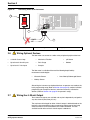
2.19.1 Bare Lead Sensor Cables
Note: Bare lead connections and
Quick-connections cannot be made
at the same time.
Bare lead sensor cables are used in those cases when the cable will be run
through a conduit. When conduit is used, it is recommended that the conduit
be 1 in. or larger to the junction box and ½ in. to the instrument.
2.19.1.1 Junction Box Connection Procedure
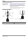
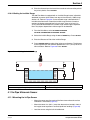
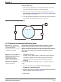
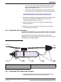
Connect the bare leads to the flow meter using a junction box (Cat. No.
9702500). This junction box is a physical connection point for the sensor wires
and breather tubing.
1. Disconnect all power to the 980 Flow Meter. Refer to Wiring Safety
Information\ on page 27.
2. Loosen the four cover screws and remove the cover from the junction box.
Unscrew the cable-clamp hex nut on the box enough to allow insertion of
the sensor cable.
3. Insert the sensor cable into the box.
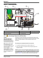
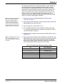
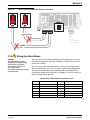
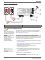
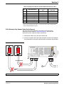
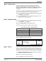
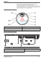
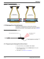
4. Refer to the wiring diagram on the inside cover of the box. Connect each
wire to its corresponding screw terminal in the upper row, according to the
wire colors listed in that diagram. See Figure 26 on page 49
Note: The submerged AV probe and
the velocity-only probe cannot be
connected at the same time.
Disconnect all bare lead
connections or submerged AV
quick-connect connections to TB11
before connecting a submerged AV
bare lead connection. Refer to
section 2.18 on page 46.
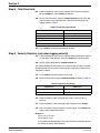
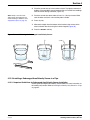
5. Connect the cable tubing to the clear tubing that is connected to the exit
fitting in the junction box.
6. Create a strain relief by slipping the cable in or out of the box to
sufficiently create a slight loop in the wires and tubing. Tighten the cable
clamp hex nut.
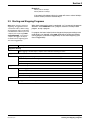
7. Verify that the sealing gasket is in place in the cover, then replace the
cover on the junction box and tighten screws.
8. Connect clear tubing between the top tubing nipple on the desiccant
canister and the brass tubing nipple on the junction box.
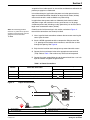
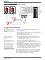
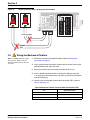
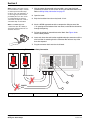
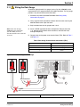
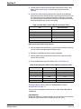
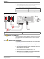
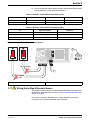
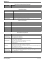
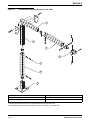
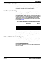
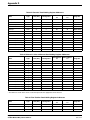
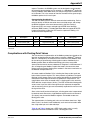
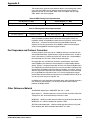
9. Connect the short, bare wire cable to TB11. Refer to Table 16 and Figure
27 on page 49.
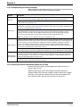
Table 16 Submerged Area Velocity Sensor Terminal Board Connections (TB11)
Pin
Signal Description
Wire Color
8
Depth + (pos)
white
9
Depth - (neg)
black
10
+ 12 V dc
red
11
common
green
12
XMIT + (pos)
gray
13
XMIT - (neg)
violet
14
RCV + (pos)
orange
15
RCV - (neg)
yellow
16
shield
clear/brown
Page 48
Wiring the Submerged Area Velocity Sensor
Installation2.fm