1
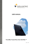
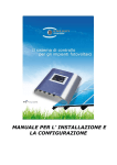
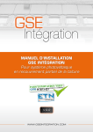
User Manual PowerSlate Mono Serie FL60® PowerSlate Multi Serie FL60® SOLUXTEC GmbH Page 1 of 12 version 1.4 - January 2014 Index of contents SOLUXTEC GmbH 1. Introduction 3 2. Basic safety instructions 4 3. Transport and storage 5 4. Installation options 6 5. Instructions for mounting 10 6. Maintenance and cleaning 11 Page 2 of 12 version 1.4 - January 2014 1. Introduction This User Manual refers to the installation, wiring, handling, maintenance and general administration of our PV-modules. Please read this manual accurately and completely before configuration and installation of the PV-plant. All advices given in this document are to be handled by a qualified person, who has due to his professional qualification the necessary technical know-how. Attention should also be paid to the live threatening risk, which may occur because of the tension in conjunction with a grid-feeding PV-plant. In case of an improper installation of the module there is a danger of fire risk. This User Manual refers to the on-roof mounting, on flat-roof bracing and on shore installations with or without tracker. In case of divergence towards this user manual SOLUXTEC GmbH does not incur liability for personal damages or property damages, which arise because of improper utilization, maintenance or incorrect assembly of the photovoltaic module. SOLUXTEC GmbH furthermore does not provide warranty for utilisability and functional capability of the laminates in that case of divergence towards the in this user manual given advices. Notice: All details given in this document are corresponding to the technical condition on creation date. Subject to modifications and amendments. SOLUXTEC GmbH Page 3 of 12 version 1.4 - January 2014 2. Basic safety instructions Risk of death by electric shock! Solar modules create electricity and are even energized under a slight illumination level. A series connection of modules leads to an accumulation of voltage. A parallel connection addition leads to an accumulation of current. The wiring of several modules to a generator control panel is only to be handled by authorized specialized staff. The network plug of the photovoltaic-panel has to be handled by a franchised certified electrician. During the assembly and handling of the photovoltaic-plant, all local legal norms, technical building regulations and accident safety regulations, especially concerning activity on the roof have to be kept. The safety instructions of all plant components as well as all regulations of the respective energy provider to the grid feeding operation of the PV-plant are to be considered. Also during low temperatures the maximum admissible open circuit voltage of the modules must not be exceeded. Never open the junction box of the photovoltaic module. Only use inspected safety equipment and tools for the installation. Risk of death by electric arc! The solar modules have to be disconnected through DC switch before the beginning of any operation on any current-carrying party of the photovoltaic-plant. Do never disconnect the solar power generator from the inverter or the assembly of the solar modules under load current. First turn off the DC switch. Please protect the panel, plug and jack against damage or dirt contamination. Do not establish a connection with dirty or wet plugs or jacks. The tools that you use for the installation have to be dry. Examine all tools for damage before the installation. Do never introduce conductive parts in the connection box and joining pieces and never try to touch the plugs on the inside. Do not modify or decompose the solar panel. And do not remove any from the manufacturer attached notices or type plates. Avoid any contact of the PV-element with metal parts. SOLUXTEC GmbH Page 4 of 12 version 1.4 - January 2014 Pay attention to all warning notices and safety indication that are attached to the panel. The realized PV generator must not be perpetrated. 3. Transport and storage During transport and interim storage the following point are to be observed: The handling with the modules should always been handled with due care. Any operation of the photovoltaic panel is to be made with clean and soft protective gloves. The laminates are very shock-sensitive. Therefore during transport, charging and discharging, storing temporarily and mounting of the PV-elements you have to be extremely careful with the handling. Never lay down the solar panels rough or on the corners and use a correspondingly soft surface. Enter the modules with both hands. Do not drop the modules. Never use the junction box as a handle bar. Pay attention on the low deflection of the modules during handling. For component storage use a dry, ventilated room. Do not accumulate the photovoltaic panels. Do not use the photovoltaic panels as a support. Keep all parts clean, which may come in contact with the PV-element. The modules are qualified for use in the application class A: Hazardous voltage (IEC 61730: greater than 50Vdc, EN 61370: greater than 120Vdc), hazardous power applications where generally unrestricted accessibility is expected (For modules in this application class according to EN IEC 61730-1 and -2 are qualified, it is assumed that they meet the requirements of protection class II) SOLUXTEC GmbH Page 5 of 12 version 1.4 - January 2014 4. Installation options Installation of a Photovoltaic Module The solar modules can be installed vertically and horizontally. For installation you have to use a suitable mounting rack. SOLUXTEC approves the application of the mounting rack and the clamp from Schletter GmbH. The mounting system belongs to the Laminate Profi Serie, the exactly type delignification of the rails are ,,Module Bearing Profile Solo 05‘‘ and those of the clamps is ,,Middelclamp or Endclamp Profi Broad 3-8mm‘‘. The fixing has to be effected on 4 points on the long side of the module. A fixing on the narrow side of the module is incorrect. To assess an ideal brick course, it is necessary to calibrate the generator control panel on roof before beginning of the installation. In doing so the rail system should be justified absolutely equal, otherwise it will come to bracing of the module and thereby it can lead to a breakage in the module. Inside the PV-plant use middle-clamps. At the borders of the PV-plant use end-clamps. The glass-clamps have to be assembled with an UV-resistant EPDM-rubber strap and they have to be adapted for modules with a glass thickness of 4mm. The substructure and the material for the fixing of the module have to be laid-out and installed, so that they resist to local burden like wind and weather. During clamping of the modules a minimum distance of 20% and a maximum distance from 25% of the long side to the narrow side has to be adhered. Both alternate clamps have to occur to the same edge distance vertically to the long side of the module. Should the modules be installed horizontally, a slight preventer is suggested. slide preventer SOLUXTEC GmbH Page 6 of 12 version 1.4 - January 2014 Further advices for installation: The clamps should not loom into the cell area of the module. The border area of a frameless module amounts to 17 mm. If different metals are used with the mounting system, pay attention to possible contact corrosion due to different fastening material. Environmental condition and asset location The laminates are intended for application in temperate zones. To avoid damaging of the module by corrosion, a minimum distance of 500m to the bordering of sea is suggested. It’s not allowed to make an installation in locations with an abnormally high chemical loading, e.g. pollution by industrial enterprises. The solar modules are not supposed to be exposed by concentrated light e.g. by mirrors bundled sunlight. The module must neither be plunged nor come in touch with a constantly water inflow like a fountain. Alignment and slope The ideal arrangement of the photovoltaic module may vary according to the location. The module surface should stay vertically to the sun to get the best possible earnings. In addition you should pay attention on the following points: The collector slope of the module should be at least 10°, based on the rainconditioned self-purification. Please avoid a partial or completely shading of the module. All module connected together in series should have the same slope in order to prevent losses in gain. Wiring A series connection can only be effected if all modules have the same current rating. In doing so attention should be paid to the tension of the module in series, the maximum tension must not exceed 1000V. For the parallel connection only modules with the same tension are to be used. If three or more strings per MPP-Tracker of the inverter are interconnected in parallel, you have to revert to a stringbox. The reverse current load capacity of the panel is 12A. Accordingly the string-box has to be equipped with string fuses with a maximum of 12A. Transformerless inverters are generally adapted. SOLUXTEC GmbH Page 7 of 12 version 1.4 - January 2014 Mechanical charges of the PV generator The modules were tested with a maximum mechanical charge of 2400 Pa (suction) and 2400 Pa (compression). Please take those maximal values into account. On installation site all present snow and wind loads and all national standards have to be considered and respected. In case of doubt please consult a mechanical stress analyst or rather an expert. Grounding and substructure Generally the laminates are frameless, so the grounding has to be effected at the metallic substructure. In general the installer has to ground the rails accordingly. The grounding has to be performed with a self-locking screw. All metallic parts of the substructure have to be connected to the main equipotential bonding of the building. The use of a cable of 10mm² is recommended for this task. The grounding has to be performed with a section of cable of 16mm² to the main equipotential bonding. If a lightning protection already exists or is planned the PV-plant has to be integrated in this concept. In doing so all related engineer standards have to be respected. In Europe the technical standard IEC 60364-7-712 has to be respected. Advice for fire protection The PV-modules are not explosion-proofed electric elements and must not be installed on explosive environment. Furthermore the installation cannot be effected near flames or on inflammable materials. The PV-modules must not be installed on flammable roofs. Further notice for wiring The planning of the wiring of the PV system should consider a tight loop wiring of the plus and minus line. The area enclosed by the conductors should be kept as small as possible. This reduces the risk of inductive coupling caused by lightning strokes. SOLUXTEC GmbH Page 8 of 12 version 1.4 - January 2014 Example of a bad wiring Example of a good wiring For the wiring of the photovoltaic system suitable cables are to be used exclusively for solar systems. Recommended are double insulated, heat-resistant UV resistant and halogen-free single core wires. The minimum conductor surface is 4mm². Refer to the instructions of the cable manufacturer ! Further Installation options: It is not allowed to install the laminates in a roof-overhanging situation. To assure an ideal operation of the PV-generator you have to mind a sufficient ventilation of the module. During operation of the PV-plant it could be that the given technical values of tension and current are in real higher than calculated before under STC. In order to prevent a possible disproportion between theoretical and real values it is recommended to add a security margin of 1,25 on all technical values including cable cross section, inverter power, etc. It has to be taken into consideration that the load of the PV-plant into the grid is balanced on all three phases of the public power grid. All technical standards for gridfeeding inverters have to be respected. In every case during development the technical data-sheet of the inverter has to be taken into account. All inverters have to respect the national and local grid-feeding standards including EMC regulations. SOLUXTEC GmbH Page 9 of 12 version 1.4 - January 2014 In any case a bi-polar DC-switch has to be installed. If it is not integrated in the inverter, this switch has to be installed as a separated part. The switch has to make sure the galvanic separation. 5. Instruction for installation The following reference notes are to be adhered during the installation on location: During work on roof all accident prevention regulations have to be respected. It is recommended to protect all uninvolved people nearby. A scaffold should be installed during work. During installation make sure not to strain the modules. If lengthening of string wiring is necessary the polarity has to be respected. The modules have to be mounted in a way which prevents rain water penetrating into the plugs. SOLUXTEC GmbH Page 10 of 12 version 1.4 - January 2014 6. Maintenance and cleaning : In general it is not necessary to clean the modules if the inclination is >10°. In case of persistent dirt use only classic glass cleaner or cleaning alcohol. Do not use galling or chemical cleaners, do not scrape the module. All modules are maintenance free, but it could be useful to verify the PV-installation regularly against following criteria’s: Integrity of the cables Fastening elements against e.g. loose brackets Cleanness, stainlessness and safe connection of all cables connections SOLUXTEC GmbH Page 11 of 12 version 1.4 - January 2014 Administration: Production: SOLUXTEC SA Route de Luxembourg, 74 L-6633 Wasserbillig Luxembourg Phone: +352-267410 Fax: +352-26741080 E-mail: [email protected] www.soluxtec.eu SOLUXTEC GmbH Werner von Siemens Straße, 25 D-54634 Bitburg Deutschland Phone: +49 (0) 6561 6937 265 Fax: +49 (0) 6561 6937 268 E-mail: [email protected] www.soluxtec.eu SOLUXTEC GmbH Page 12 of 12 version 1.4 - January 2014