1
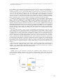
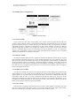
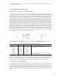
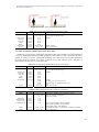
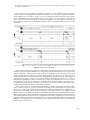
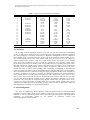
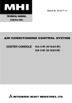
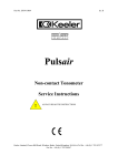
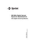
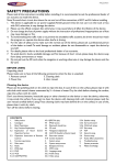
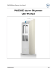
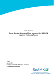
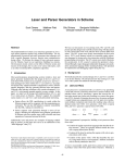
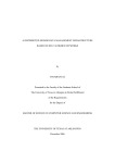
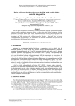
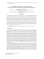
An Intelligent Standby Power Control System Design based on User Location and Appliance Usage Pattern in Smart Home
Kyoung-Mi Im, Jae-Hyun Lim
An Intelligent Standby Power Control System Design
based on User Location and Appliance Usage Pattern in Smart Home
1
Kyoung-Mi Im, 2Jae-Hyun Lim
Green Energy Technology Research Center, Kongju National University,
[email protected]
*2
Department of Computer Science and Engineering, Kongju National University,
[email protected]
1
Abstract
The standby power controlling system that is currently used works by automatically blocking
standby power upon sensing the use of electricity or by the user’s manual on/off controlling. As this
type of system, however, requires the voluntary participation of the user for resupply of electric power,
it causes inconvenience to the user and necessarily involves the user’s intervention for power saving,
which is the significant disadvantage of this system. In consideration of user convenience as well as
standby power saving, this study suggests a system that automatically blocks and resupplies standby
power depending on the user’s utilization pattern and movement within an appliance’s sensing zone.
The system is a ZigBee structure based on IEEE 802.15.4, a low electric power wireless network, and
two narrow angle–type PIR sensors are installed at the entrance and given an ID each so that they can
recognize the entrance and exit of users in the order of ID sensing. In addition, one ultrasonic sensor is
installed for sensing the user’s key, thus recognizing the user. To verify the standby power saving
effects of the suggested system, scenarios were made for each user’s pattern, and the quantity of
standby power saving was comparatively analyzed.
Keywords: Standby Power, Energy Saving, ZigBee, User Location, Context Awareness
1. Introduction
Throughout the world, energy prices are increasing as energy resources are declining. Climate
change has become a global issue as greenhouse gas emissions increase. Accordingly, countries are
actively promoting energy efficiency policies to reduce energy consumption [1]. Korea, for example, is
the 9th highest energy consuming country in the world in 2011, and it has been reported that the
increase rate of carbon emission in this country was the highest in the year [2]. NIA(National
Information Society Agency) of Korea estimates that domestic CO2 emission increases about 2.2% on
average every year, and that in 2012, the amount will reach 688 million tons. The CO2 emission in the
IT sector is expected to account for 3.1% of the entire emission, which is far higher than the global
average emission of 2.0%. This present state results from rapid changes in demands for electric power
and in product market conditions, including the emergence of products that consume a lot of energy in
the application of IT. This trend is expected to continue in the future as electronic products, as well as
IT, become more advanced. As the number of office devices, such as copy machine, fax machine,
computer, and printer, as well as “always-on” devices like home network and set-top boxes that work
24 hours a day, increases, the issue of energy efficiency among electric appliances in line with the
advancement of energy saving technology is highlighted, not only due to the electricity consumption
generated in the use of these devices, but also due to the power consumption they engender during
standby mode [3-7].
IEA(International Energy Agency) estimates that in OECD’s 34 member countries, each household
consumes standby power as high as 60W, which is about 10% of its total power consumption. In the
case of the U.S., the standby power consumption is 5% of the entire electric power consumption, which
is relatively small, but this amounts to about 1.3 billion dollars every year, which indicates that the
issue of standby power consumption should not be overlooked anymore [8]. According to KERI
(Korea Electrotechnology Research Institute), in Korea in the year 2011, standby power as much as
209kWh per household was consumed during the year, which accounts for 6.1% of the total electric
power consumption (3400kWh) of one household during the year. According to one research, if
appliances not used were plugged off, electric energy as much as 17.4kWh could be saved every month
Journal of Convergence Information Technology(JCIT)
Volume8, Number8, April 2013
doi:10.4156/jcit.vol8.issue8.146
1231
An Intelligent Standby Power Control System Design based on User Location and Appliance Usage Pattern in Smart Home
Kyoung-Mi Im, Jae-Hyun Lim
[9]. In addition, it is estimated that each household in Korea owns 23.9 units of home appliances. As
the types of appliances become diversified, the number of devices owned in each household is
increasing as much as 1.5 every year, and the number of network devices is increasing as well. Thus, it
is expected that during the following 20 years, the standby power consumption will increase about
5.8% every year [9]. If things continue at this pace, the standby power consumption by 2020 will
account for about 25% of the entire household power consumption [3]. However, most home appliance
users are not aware of the necessity of saving electric power and resources by minimizing standby
power consumption; thus, a system to technically reduce the consumption must be developed.
In 2004, the Korean government issued a proclamation that it would introduce “Standby Korea
2010” to manage the standby power of all electronic appliances under 1W. In this effort to develop
standby power saving technology, it will provide purchasing, distributing, and promoting support for
the technology [10][11]. Accordingly, the standard of standby power measuring 1W or less was
applied to 30 kinds of electronic products released up to 2010. As a result, 170kWh for each household
and 2,550GWh nationwide were saved. By 2020, it is estimated that 2,800kWh for each household and
42,000GWh nationwide will have been saved [12][13]. Despite such efforts, however, a number of
electronic products with more than 1W standby power still require manual control for standby power
blocking and supply, which indicates the necessity for the consumer’s active participation for standby
power saving.
Thus, this study intends to design a system to intelligently and automatically control the on/off
modes standby power by grasping the location and usage patterns of users within a zone as well as
reducing standby power consumption that is wasted with the user not noticing it. The suggested system
recognizes users to control or prevent the consumption of standby power of appliances that are not
often used by the users with the power supplied for all devices in the zone as the system senses their
presence. Afterwards the system supplies electric power only to devices that the user in its presence
would consistently use. The data containing the user’s entrance and exit are acquired by means of the
two PIR sensors at the entrance of each zone, and the data for user recognition are obtained through
key sensing from the ultrasonic sensor at the entrance of each zone. Furthermore, the system changes
the frequency of use of each device once it senses any change in the list of major appliances used,
which is reflected as it decides to block or supply standby power to certain devices upon the user’s
entrance.
This study consists of the following sections: Chapter 2 presents existing studies on standby power;
Chapter 3 states the intelligent standby power control system suggested in this study; Chapter 4
evaluates it by comparing the system with existing standby power devices based on the scenarios;
Chapter 5 presents the conclusion and issues for future study.
2. Related work
Standby power is the electricity consumed by appliances while switched off or not
performing their primary functions [14]. In other words, standby power means the electric
power consumed while the devices are plugged in and with the major functions in an idle state
as in Figure 1.
Figure 1. Standby power
1232
An Intelligent Standby Power Control System Design based on User Location and Appliance Usage Pattern in Smart Home
Kyoung-Mi Im, Jae-Hyun Lim
IEC (International Electrotechnical Commission), IEA, the U.S., Japan, Australia, etc. have their
definitions of standby power, and there has been no unified, international terminology in this regard.
The IEC defines standby power is the lowest level of electricity consumed by appliances, which cannot
be switched off (influenced) by the user, and may persist for an indefinite time when an appliance is
connected the main electricity supply [15]. The Korea Energy Management Corporation defines
standby power as “power consumed while the device is connected to the power source and waiting for
ON signals from outside with the major functions in an idle state, including the consumption upon
power-off and during the warming up and booting of the device” [16].
It is difficult to apply a definition of standby power in all machines since the running and operating
patterns of appliances and office devices are different. Thus, the term may be classified into no-load,
off mode, passive standby, active standby, and sleep mode depending on whether the running totally
stops or remains minimized with the plug on as in Table 1. Power consumption with no operation at all
is called the off mode standby power, the consumption when the power is turned off by means of a
remote controller passive standby, the consumption when the power of a networked digital appliance is
turned off active standby, and the consumption in a standby state for normal operation of the device
sleep mode standby power [15][16]. Appliances distributed before mostly had only off mode, passive
standby, and sleep mode, but as network devices have become common recently, standby power
consumption at active standby mode has been increasing. Introduced with the emergence of the set-top
box system, active standby indicates a state that consumes a lot of standby power, with the internal
circuit operating in order to wait for wire/wireless communication signals from outside even if the
consumer has turned the system off. It has been estimated that standby power consumption could
measure as much as 3-4W on average, and 10W at most [17]. If just one set-top box system silently
consumes 20-40W on standby power, taking measures on this becomes of great urgency.
Category
No Load
Off
Passive
Standby
Active
Standby
Sleep
Table 1. Types of standby power
Description
Power Status
Power consumed with the plug on
Switched off
Power consumed even with the power
turned off through the power on/off
button; about 0-3W
Power consumed with power turned
off through a remote controller
As for digital devices connected to a
network, standby power as much as
20-40W
is
consumed
for
communication with the power on
even if it is switched off
Power consumed in a standby state
that would not be used while the
device is working
Switched off
Switched off
Switched off
On and standby
Products
External
Power
Supply,
electric rice cooker
TV, VCR, audio, DVD player,
microwave, PC, monitor,
printer, copier
TV, VCR, audio, DVD player,
air cleaner, air conditioner
Set top box, home network
system
PC,
monitor,
printer,
facsimile, copier, scanner,
multifunction device
Every product with a power on/off switch consumes a measure of standby power, especially
electronic products such as consumer electronics, office equipment, and white goods whose standby
time is a lot longer than their operating time, thereby consuming a large amount of standby power.
Figure 2 shows the minimum, average, and maximum standby power measured from each electronic
product, as well as the number of products measured at Lawrence Berkeley National Laboratory. It
indicates that office devices and digital appliances connected to a network consume a particularly high
level of standby power [17].
The best way to block standby power is to plug it off completely. Standby power-saving devices
developed so far focus on user convenience by such means as remote controller or timer that blocks
power supply automatically after a certain time period. Some methods induce users to check power
consumption and control power supply for themselves. Most of the methods above, however, require
the voluntary participation of the device users, and even auto plug-off methods require the user’s
manual intervention for resupply of power, which causes inconvenience. In the case of active standby,
especially, standby power consumption continues for at least 20 hours a day; thus, it is necessary to
1233
An Intelligent Standby Power Control System Design based on User Location and Appliance Usage Pattern in Smart Home
Kyoung-Mi Im, Jae-Hyun Lim
develop a device and system that can automatically block and resupply power without the user’s
intervention.
Figure 2. Standby power of products
3. Intelligent standby power control system
The intelligent standby power control system suggested in this study is designed based on the IEEE
802.15.4 ZigBee technology which is one of the most common low-power consumption
communication technologies in the market [18-20]. As shown in Figure 3, it includes two PIR sensors
to recognize entrance and exit in several locations and an ultrasonic sensor to identify the persons. At
each section, some appliances subject to standby power controlling are arranged, and their standby
power is controlled by the processor of the suggested Intelligent Standby Power Control System
depending on the condition.
Figure 3. Structure of intelligent standby power control system
1234
An Intelligent Standby Power Control System Design based on User Location and Appliance Usage Pattern in Smart Home
Kyoung-Mi Im, Jae-Hyun Lim
3.1. Standby power saving devices
Figure 4. System design
3.1.1. Context module
Figure 4 shows the flow chart of the standby power control system developed in this study. The
system’s context collector collects raw data from the PIR sensors and the ultrasonic sensor recognizes
the users and their locations at certain intervals. The collected raw data is processed by the context
aggregation processor, interpreted for information on the system condition, and saved so that the
context interpretation processor can recognize the situation. The raw data received from the PIR
sensors is compared with the sensor ID information stored in the database in order to recognize the
entrance, exit, and location of the user. The raw data received from the ultrasonic sensor is compared
with the user information to recognize certain users.
3.1.2. Inference module
The Inference Module infers the users’ appliances enlisted in the database based on the user location
and recognition information stored in the context module. When the user uses appliances other than
those in the list stored in the database, the history of using appliances in the database is updated, and
the list of appliances whose use frequency is reduced is changed accordingly. Afterwards, the service
reasoning processor infers the user’s appliances from the database of the history of appliance uses. If
more than one user is recognized in the same zone, the system counts the number of users and supplies
power to all appliances for them.
3.1.3. Standby power module
Once the users and their movements are recognized, the Power Control Management checks the IDs
of the appliances in a zone, grasps the list of appliances for certain users from the database, and sends
signals of power-on or power-off to the actuator of the electric Powermeter. Supplied with power, the
Powermeter sends the data on power consumption through the gateway by means of Power
Measurement Management. If the user wants to use an appliance not registered in the database, power
is supplied by manual controlling of the Powermeter in the system, and the system saves the use
history of the appliance and time of use in the database.
3.1.4. Timer module
If the user who is working in the zone leaves the area with a certain appliance on and does not come
back for a period of time, the Power Time Over processor blocks the power supply automatically,
which saves standby power and thus reduces the general waste of electric power.
1235
An Intelligent Standby Power Control System Design based on User Location and Appliance Usage Pattern in Smart Home
Kyoung-Mi Im, Jae-Hyun Lim
3.2. Transmission and reception of data
3.2.1. Checking of a Certain User’s Entrance and Exit
To grasp a user’s entrance or exit into a zone and count the number of people present, the suggested
system adopts PIR sensors. PIR sensors recognize the infrared light from human bodies and
movements in a zone to grasp a user’s presence. These PIR sensors, however, may not recognize any
presence if the user is located at a blinded area in the zone or the movement is too insignificant to be
sensed. Multiple sensors may be necessary depending on the size of the zone, and the number of users
in presence may not be recognized. Hence, the system suggested in this study uses the two PIR sensors
with an ID each at the entrance to count the number of users in the zone and check their entrance or
exit as in Figure 5(b). The system recognizes a user by means of the first PIR sensor in the order of IDs
saved in the PIR sensor, and then the entrance is recognized when the second PIR sensor recognizes
the user. Likewise, when the second PIR sensor recognizes movement and the user’s movement is
sensed by the first PIR sensor, an exit is recognized. The system’s PIR sensor transforms the infrared
light in the 95°×90° range into a voltage for sensing as shown in Figure 5(a). However, when the two
PIR sensors installed in the entrance of the zone maintain an existing wide angle as in Figure 5(a), it
frequently occurs that at the intersection of the two sensors, exit is mistakenly recognized right after
one’s entrance. The system, therefore, changed the sensing angle of the PIR sensors to a narrow angle
as in Figure 5(b) to correctly recognize entrance and exit.
Figure 5. Changes in the Sensing Angle of the PIR Sensors to Recognize One’s Presence Correctly
Packet
Table 2. Receiving packet information of PIR sensor
Length
No
Description
Header
10 bytes
Sensor Type
Serial ID
Node ID
Count
Battery
Sensor Data
Footer
2 bytes
6 bytes
2 bytes
2 bytes
2 bytes
6 bytes
3 bytes
0 / 1 / 2 / 3-4
5-6 / 7 / 8 /9
10-11
12-17
18-19
20-21
22-23
24-25 / 26-29
30-31 / 32
STX(0x7E) / Receiving(0x45) / 0x00 / Dest
Src / Length / Group ID / Type
0x0065
Sensing(Off : 0x0000, On : 0x0001) / Dummy
CRC / ETX(0x7E)
The packet of each PIR sensor transmitted to the gateway is 33 bytes in total as shown in Table 2.
Presence is sensed based on the received values of numbers 24 to 25. If more than one user enters the
same zone, the signals of entrance are delivered from the PIR sensors twice, and then the system
increases the number of recognized users at every signal reception and saves it in the database.
3.2.2. Receiving User-recognition Data
The suggested system adopts an ultrasonic sensor to recognize users. The sensor is installed at the
top of the entrance as in Figure 6, and the result is delivered except on the area covering the ground up
to the upper end of the user’s height. Table 3 shows the data packet structure of the ultrasonic sensor in
a table. The key information is received from packets 24 and 25 of the sensor data, and the received
values are compared with those in the user-recognition table stored in the database to recognize certain
users.
1236
An Intelligent Standby Power Control System Design based on User Location and Appliance Usage Pattern in Smart Home
Kyoung-Mi Im, Jae-Hyun Lim
Figure 6. Ultrasonic sensor to recognize certain users
Packet
Table 3. Receiving packet information of ultrasonic sensor
Length
No.
Description
Header
10 bytes
Sensor Type
Serial ID
Node ID
Count
Battery
Sensor Data
Footer
2 bytes
6 bytes
2 bytes
2 bytes
2 bytes
6 bytes
3 bytes
0 / 1 / 2 / 3-4
5-6 / 7 / 8 / 9
10-11
12-17
18-19
20-21
22-23
24-25 / 26-29
30-31 / 32
STX (0x7E) / Receiving (0x45) / 0x00 / Dest
Src / Length / Group ID / Type
0x0069
Height / Dummy
CRC / ETX (0x7E)
3.2.3. Data Transmission and Reception of the Powermeter
Installed to grasp the power consumption of appliances and control standby power, the Powermeter
is a power consumption measuring module designed to collect data on power consumption through a
gateway by means of a power consumption measuring chip. Table 4 shows the packet information
received from the Powermeter. The values of current, active power, apparent power, and peak are
obtained from numbers 24 to 35 of the sensor data.
Packet
Table 4. Receiving packet information of electric powermeter
Length
No.
Description
Header
10 bytes
Sensor Type
Serial ID
Node ID
Count
Battery
Sensor Data
2 bytes
6 bytes
2 bytes
2 bytes
2 bytes
12 bytes
Footer
3 bytes
0 / 1 / 2 / 3-4
5-6 / 7 / 8 / 9
10-11
12-17
18-19
20-21
22-23
24-26
27-29
30-32
33-35
36-37 / 38
STX (0x7E) / Receiving (0x45) / 0x00 / Dest
Src / Length / Group ID / Type
0x006D
Current
RawEnergy for Active Power (W)
RawVAEnergy for Apparent Power (VA)
Peak
CRC / ETX (0x7E)
Packet
Table 5. Sending packet information of electric powermeter
Length
No.
Description
Header
11 bytes
Source ID
Destination ID
Sensor Type
Command Type
2 bytes
2 bytes
2 bytes
2 bytes
0/1/2/3
4-5 / 6-7 / 8 / 9
10
11-12
13-14
15-16
17-18
Action
Footer
4 bytes
3 bytes
19-20 / 21-22
23-24 / 25
STX (0x7E) / Sending (0x44) / Sequence / 0x00
Dest / Src / Length / Group ID)
MSG Type (0x88)
LED_Toggle (0x0001), Reboot (0x0002),
GPIO_Control (0x0003), Ping (0x0004),
RSS (0x0005), NET_Info (0x0006)
Port Number (0x0051) / Control (Off : 0x0000, On: 0x0001)
CRC / ETX (0x7E)
1237
An Intelligent Standby Power Control System Design based on User Location and Appliance Usage Pattern in Smart Home
Kyoung-Mi Im, Jae-Hyun Lim
Once the recognition of users and their entrance are completed, signals triggering On/Off modes are
transmitted to the actuator to supply or block power in a zone. The output values at GPIO (General
Purpose Input/Output)—0x0000 and 0x0001—indicate the blockage and supply of power respectively
shown in packets 21 and 22 in Table 5.
4. Simulation and evaluation
To evaluate the amount of standby power saving through the suggested system, this study simulates
the four divided sections as in Figure 7 and installs at the entrance two PIR sensors and one ultrasonic
sensor to recognize user identification and their entrance and exit. In each section, the electric
powermeters are arranged from E1 to E20 to control the power consumption data transmission as well
as standby power. Two individuals—A and B—are involved in the simulation as users. A is 165cm and
B is 175cm. Thus, the range of identification values for users in the ultrasonic sensor is 39cm and
29cm respectively since the values are to be the height of the door, which is 204Cm, subtracted by each
user’s height. In the case of Section A, movement is recognized as entrance into Sections B, C, and D.
If no presence signals are recognized in Section B, C, or D, and exit signals are recognized instead in
Section A, the system regards it as exit from the entire space.
Figure 7. Environment of test bed
Section
A
B
C
D
Table 6. Standby power of test bed
Appliance
ID
Standby power
TV
1
Set-Top Box
2
Audio System
Air Conditioner
(Stand)
Air Cleaner
Coffee Maker
Microwave Oven
Washing Machine
Refrigerator
Dishwasher
Electric Rice Cooker
TV
DVD/VCR
Charger, Mobile Phone
Humidifier
Lamp
Computer Desktop
Computer Display, LCD
Printer, Laser
Air Conditioner
(Wall)
User
A, B
3
4.33 W
16.82 W(Active)
0.7W (Passive)
9.12 W
4
5.81W
B
5
6
7
8
9
10
11
12
13
14
15
16
17
18
19
0.7W
1.2W
3.72W
1.9W
Consistent power supply
2W
3.5W
1.3 W
12.2W
0.86 W
3.72W
3W
3.26W
2.53W
3.07W
B
A, B
A, B
B
A, B
A
A,B
A
A
B
B
A
B
B
B
20
1W
A, B
A, B
A
1238
An Intelligent Standby Power Control System Design based on User Location and Appliance Usage Pattern in Smart Home
Kyoung-Mi Im, Jae-Hyun Lim
Table 6 shows the IDs of appliances installed in each space, average standby power consumption,
and list of users of each appliance registered in the database. The set-top box in Section A consumes
active standby power as much as 16.82W even if it is switched off while connected to the network.
This is recognized and managed as standby power, not firm power. The refrigerator in Section B is a
device where power must be supplied to consistently regardless of a user’s presence, thus standby
power blockage packets are not transmitted while the power consumption data is received in the
experiment.
Figure 8. Scenario for experiment
Figure 8 shows the movement of users A and B and use of appliances for each time section of the
24 hours. The system supplies standby power to appliances listed in the database once it recognizes the
entrance of the user. If the entrance of both A and B is recognized in the same section, the system
supplies standby power to appliances in the list applied for both. If no presence is recognized in every
section, the standby power and current power consumption are blocked except for items subject to
consistent power supply. However, the washing machine, dishwasher, and electric rice cooker in
Section B are regarded as exceptions, and their power supply is not blocked even if the user’s exit is
recognized from every section. If the device is turned from use mode to standby power mode, this is
recognized and standby power is blocked. If user is staying in the same section for more than 1 hour,
standby power of appliances that user does not use is blocked
Table 7 shows the result of analyzing the consumption of standby power during the day according
to the scenario in Figure 8. System A simulates the standby power consumption in a system where
there was no standby power blockage while System B simulates the standby power consumption in a
system where the standby power blockage and supply were carried out for every appliance in the
sections. System C shows the standby power consumption when the system suggested in this study is
adopted. The standby power consumption in each case was 645.85W, 182.5W, and 120W, respectively,
which indicates that the suggested system consumed the least amount of standby power. Moreover, the
suggested system minimizes the manual intervention of users and intelligently controls the supply and
blockage of standby power for user convenience. Thus, standby power consumption is reduced while
the user does not even notice it.
1239
An Intelligent Standby Power Control System Design based on User Location and Appliance Usage Pattern in Smart Home
Kyoung-Mi Im, Jae-Hyun Lim
Table 7. Comparison of standby power consumption
Used time
System A
System B
ID
1
2
3
4
5
6
7
8
9
10
11
12
13
14
15
16
17
18
19
20
90 minutes
90 minutes
30 minutes
90 minutes
90 minutes
60 minutes
24 hours
60 minutes
120 minutes
60 minutes
60 minutes
9 hours
120 minutes
120 minutes
Total Standby Power
97.425W
15.75 W
214.32 W
139.44 W
16.8 W
27 W
83.7 W
43.7 W
46 W
77 W
29.9 W
280.6 W
20.64 W
89.28 W
45 W
71.72 W
55.66 W
73.68 W
24 W
1451.615 W
4.33W
0.7W
18.24W
14.525W
1.75W
2.4W
7.44W
4.75W
5W
5.25W
11.7W
109.8W
8.6W
37.2W
3W
26.08W
20.24W
30.7W
10W
321.705W
System C
4.33W
0.7W
4.56W
11.6W
1.05W
1.8W
5.58W
1.9W
4W
4.67W
1.3W
12.2W
0W
0W
3W
3.26W
2.53W
9.21W
3W
74.69 W
5. Conclusion
As the usage of home appliances increases every year, not only does total power consumption
increase, standby power consumption also rises while the devices are plugged in. Recently, appliances
have been grouped in a network by such means as ubiquitous, intelligent home net, etc., leading to
drastic standby power consumption changes. Devices such as the set-top box, XDSL modem, TV, PC,
etc. consume standby power in the active standby mode more than before to serve the purpose of
constant communication 24 hours a day. As a result, various devices and systems to save standby
power have been introduced, but most of them are operated by users manually, which causes
inconvenience and achieves no standby power saving without the user’s voluntary intervention. Thus,
this study suggests the standby power control system that blocks and supplies power automatically
depending on the movement, location, and user pattern of appliances with no need for the user’s
manual intervention in order to reduce standby power consumption in households. In particular, this
system recognizes the entrance and exit of multiple users by installing PIR sensors and an ultrasonic
sensor in divided sections to control the blockage and supply of appliance standby power depending on
the history of appliance use of those in presence. For intelligent controlling, the system minimizes a
user’s manual control of standby power and updates the users’ appliance use pattern based on their
history of use. In the experiment, the area was divided into several sections, and scenarios were made
in a way that involved different locations and use patterns of appliances depending on two users’
preferences. The case where the suggested system applies and the other case where it does not are
compared to evaluate the amount of standby power saved. In future studies, standby power control
system that can predict user patterns depending on human traffic and that can block power supply on
unused appliances accordingly are expected to be examined.
6. Acknowledgement
This work was supported by Priority Research Centers Program through the National Research
Foundation of Korea (NRF) funded by the Ministry of Education, Science and Technology (20120006682). It was also supported by Basic Science Research Program through the National Research
Foundation of Korea(NRF) funded by the Ministry of Education, Science and
Technology(2012R1A1A4A01013068).
1240
An Intelligent Standby Power Control System Design based on User Location and Appliance Usage Pattern in Smart Home
Kyoung-Mi Im, Jae-Hyun Lim
7. References
[1] Liping Fan, Chong Li, Xiaolin Shi, “Adaptive Fuzzy Control of a Proton Exchange Membrane
Fuel Cell”, International Journal of Digital Content Technology and its Applications, AICIT, vol.
7, no. 1, pp.41-49, 2013.
[2] Christ of Ruhl, “BP Statistical Review of World Energy”, BP:http://www.bp.com/, 2012.
[3] K.-M Im, C.-S. Kim, J.-H. Lim, “Standby Power Control System based on User’s Location for
Energy Saving in Smart Home”, Advances in Intelligent and Soft Computing, Springer, vol. 125,
no. 1, pp. 213-220, 2012.
[4] Z.-H. Ye, Y.-D. Ji, S.-Y. Yang, “Home Automation Network Supporting Plug and Play”, IEEE
Transactions on Consumer Electronics, IEEE, vol. 50, no. 1, pp. 173-179, 2003.
[5] J. Heo, C.-S. Hong, S.-B. Kang, S.-J. Sang, “Design and Implementation of Control Mechanism
for Standby Power Reduction”, IEEE Transactions on Consumer Electronics, IEEE, vol. 54, no. 1,
pp. 179-185, 2008.
[6] IEA, “TOWARD A CLEAN, CLEVER & COMPETITIVE ENERGY FUTURE”,
IEA:http://www.iea.org/, 2007.
[7] Ju-Yong Kim, June-Whan Choi, Yong-Sul Kim, “Design of the Low Energy Consuming SMPS
(Switched-Mode Power Supply) System using the Solar Cell”, International Journal of
Engineering and Industries, AICIT, vol. 2, no. 4, pp.106-113, 2011.
[8] IEA, “ ENERGY TECHNOLOGY PERSPECTIVES 2006”, IEA:http://www.iea.org/, 2007.
[9] KERI, “An actual survey of standby power all over the country in 2011”, KERI
Newsletter:http://www.keri.re.kr/, 2012.
[10] IEA, “Energy Policies of IEA Countries(THE REPUBLIC OF KOREA 2006 Review)”, IEA
Country Review:http://www.iea.org/, 2006.
[11] IEA, “Progress Implementing the IEA 25 Energy Efficiency Policy Recommendations”,
IEA:http://www.iea.org/, 2012.
[12] Y. Kim, “Negative Label Positive Step Standby Warning Label and Korea 1W Policy”, APEC
Standby Power Conference-Moving Towards 1Watt and Beyond, 2010.
[13] Y. Kim, “Perspective and Problems of Standby Power 1 Watt Policy”, The proceedings of KIEE,
vol. 59, no. 1, pp. 35-40, 2010.
[14] IEA, “Standby Power Use and the IEA “1-watt Plan””, IEA:http://www.iea.org/, 2012.
[15] NRCAN(Natural Resources Canada), “Canada’s Energy Efficiency Regulations”,
http://oee.nrcan.gc.ca/, 2009.
[16] KEMCO(Korea Energy Management Corporation), “Korea’s 1-watt Plan Standby Korea 2010”,
http://www.kemco.or.kr/, 2010.
[17] Lawrence Berkeley National Laboratory, “Standby power summary table”, http://standby.lbl.gov/,
2012.
[18] Ed Callaway, Paul Gorday, etc., “Home Networking with IEEE 802.15.4:A Developing Standard
for Low-Rate Wireless Personal Area Networks”, IEEE Communications Magazine, IEEE, vol.
40, no. 8, pp. 70-77, 2002.
[19] J. A. Gutierrez, E. H. Callaway and R. L. Barrett, Low-Rate Wireless Personal Area Networks,
IEEE Press, New York, 2003.
[20] Fashan Yu, Mingjie Zong, “Research of Intelligent Illuminating Control System”, International
Journal of Advancements in Computing Technology, AICIT, vol. 5, no. 4, pp. 483-490, 2013.
1241