1
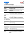
IV.1.-MOULD ASSEMBLY ON INJECTION MACHINE
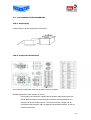
1. Mould assembly on injection machine, ensuring that flow channel diameter of
machine nozzle is approximately 1mm smaller than flow channel diameter of access
nozzle to Hot Runner Systems.
2. Connect and check water lines
3. Connect and check hydraulic/pneumatic lines.
4. Connect all electric components.
IV.2.- START
1. Switch mould cooling system on.
2. Heat injection machine oil to working temperature.
3. Heat hot runner system to correct processing temperature.
4. Expel material of hot runner system at appropriate temperature.
5. Adjust injection process conditions to part size, gate size, meterial, etc.
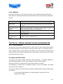
CHAPTER VI: POTENTIAL FAULTS
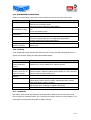
VI.1.- FLOW SIGN
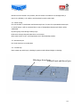
There are 3 types:
-
“water” around injection point or distributed around all cavity, due to melt cools
before to mould adjustment.
-
Humidity flashing, on matt colour generally, its cause can be material humidity or
material degradation around injection point.
-
“Jetting”, due to unbalanced flow of melting.
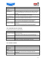
CAUSE
REMEDY
Turbulences during
filling due to
inadequate injection
Hardening plastic
before filling cavity
Turbulences during
filling by inadequate
finding of gate
Injection machine: adjust injection flow to fill cavity slowly: reducing
speed and pressure of injection.
Injection Machine: cooling reduction till full cavity filling. Increase valve
Mould: Increase mould temperature.
Mould: Change gate location in order for material to come into contact
with a mould surface.
10-12