1
Allen-Bradley
Bulletin 161
AC Drive
(Series B)
0.2-3.7kW
(0.3 to 5 hp)
FRN 2.001
User
Manual
Important User Information
Solid State equipment has operational characteristics differing from those of electromechanical
equipment. ªSafety Guidelines for the Application, Installation and Maintenance of Solid-State
Controlsº (Publication SGI-1.1) describes some important differences between solid-state
equipment and hardwired electromechanical devices. Because of this difference, and also because
of the wide variety of uses for solid-state equipment, all persons responsible for applying this
equipment must satisfy themselves that each intended application of this equipment is acceptable.
In no event will Rockwell Automation be responsible or liable for indirect or consequential damages
resulting from the use or application of this equipment.
The examples and diagrams in this manual are included solely for illustrative purposes. Because of
the many variables and requirements associated with any particular installation, Rockwell
Automation cannot assume responsibility or liability for actual use based on the examples and
diagrams.
No patent liability is assumed by Rockwell Automation with respect to use of information, circuits,
equipment, or software described in this manual.
Reproduction of the contents of this manual, in whole or in part, without written permission of
Rockwell Automation is prohibited.
Throughout this manual we use notes to make you aware of safety considerations
ATTENTION:
Identifies information about practices or circumstances that can lead to
personal injury or death, property damage or economic loss.
Attention statements help you to:
● Identify a hazard
● Avoid a hazard
● Recognize the consequences
IMPOR TAN T: Identifies information that is especially important for successful application and
understanding of the product.
Shock Hazard
present.
labels located on or inside the drive indicate that dangerous voltage may be
Table of Contents
1. Getting Started ........................................................................................
Important Precautions
Conventions used in this manual
Catalog Number Explanation
Receiving Your New Drive
Nameplate Label
Drive Features
p.1
p.2
p.2
p.3
p.3
p.4
2. Installation & Wiring ...............................................................................
Storage and Operating Conditions
CE Compliance
Installation
Clearances
Terminal Blocks
Power Wiring
Power Terminal Block Wiring Specifications
Branch Circuit Protection Devices
Input Power Conditioning
Grounding
Control Wiring
Control Terminal Descriptions
Programmable Digital Input (Control terminal block inputs 1 through 5) Functions
p.5
p.5
p.5
p.5
p.6
p.7
p.8
p.8
p.8
p.8
p.9
p.10
p.12
3. Parameters & Programming ..................................................................
Programming Keypad
Programming Examples
Initial Power Up
Scrolling through parameter groups
Operation of the Drive via the Fixed Keypad
Activating the Speed Pot on the Keypad
Restoring Factory Defaults
Parameter Groups
Parameter Descriptions
d Group - Display and Diagnostic Parameters (Read Only)
F Group – Basic Function Parameters
A Group – Advanced Function Parameters
b Group – Advanced Control and Protection Parameters
C Group – Intelligent I/O and Communication Parameters
p.15
p.16
p.16
p.16
p.17
P.17
p.18
p.19
p.21
p.21
p.22
p.22
p.29
p.33
4. Faults & Troubleshooting ......................................................................
Fault Information
How to Clear a Fault
Bulletin 161 Fault Descriptions
Possible Problems and Corrective Actions
Other Displays
p.35
p.35
p.35
p.36
p.37
i
5. Specifications & Dimensions ................................................................
Technical Data
Dimensions
Accessories
p.39
p.40
p.42
A. CE Conformity ........................................................................................
CE Compliance
General Notes and Instructions
Essential Requirements for a Conforming EMC Installation
Motor Cable
Control Cable
ii
p.43
p.43
p.43
p.43
p.43
Chapter 1 – Getting Started
Important Precautions
In addition to the precautions listed throughout this manual, you must read and understand the following
statements which identify hazards associated with AC drives.
ATTENTION
The Bulletin 161 drive contains high voltage DC bus capacitors which take time to discharge after
removal of input power. Before working on the drive, wait five minutes for capacitors to discharge to
safe voltage levels.
Darkened display LEDs are not an indication that capacitors have discharged to safe voltage levels.
Failure to observe this precaution could result in severe bodily injury or loss of life.
ATTENTION
This Bulletin 161 drive generates dangerous electrical voltages and controls potentially dangerous
rotating mechanical parts. Disregarding the guidelines provided in this manual could result in severe
bodily injury or loss of life.
Only personnel familiar with the drive and associated machinery should plan or implement the
installation, start-up and subsequent maintenance of the system. Failure to comply could result in
bodily injury and/or damage to the equipment.
ATTENTION
This drive contains ESD (Electrostatic Discharge) sensitive parts and assemblies. Static control
precautions are required when installing, testing, servicing or repairing this assembly. Component damage
may result if ESD control procedures are not followed. Failure to observe this precaution could result in
damage to the equipment.
ATTENTION
The drive is intended to be installed with a fixed ground connection. The protective ground only offers
protection for the drive, not against personal injury. According to EN 50178 it is not recommended to use
the Bulletin 161 drives on protective fault current switches as, due to a possible DC component (rectifier
load), the sensitivity of the safety switch will be reduced in the event of a failure. If unavoidable, only type
B Residual Current Operated Protective Devices (RCD’s) should be used. As a precautionary measure,
the EN 50178 regulations should be observed. Failure to observe this precaution could result in severe
bodily injury or loss of life.
ATTENTION
An incorrectly applied or installed drive can result in component damage or reduction in product life.
Wiring or application errors such as undersizing the motor, supplying an incorrect or an inadequate AC
supply, or excessive ambient temperatures may result in system malfunction. Failure to observe this
precaution could result in damage to the equipment.
1
Getting Started
ATTENTION
•
To prevent any injuries or damage, do not touch any components located within the housing with
your hands or with any other objects while input voltage is applied or if the DC-bus capacitors are
not discharged. Do not carry out any work on the wiring or check any signals if input voltage is
applied.
ATTENTION
•
Ensure that the input voltage corresponds to the voltage indicated on the product nameplate.
Environmental influences such as high temperatures and high relative humidity are to be avoided as
well as dust, dirt and corrosive gases. The mounting location should be well ventilated and not
exposed to direct sunlight. Install the device upright on a non-flammable, vertical wall. Failure to
observe this precaution could result in damage to the equipment.
ATTENTION
•
The drive start/stop and enable control circuitry includes solid-state components. If hazards due to
accidental contact with moving machinery or unintentional flow of liquid, gas or solids exist, an
additional hardwired stop circuit is required to remove AC input power to the drive.
•
All the pertinent safety regulations, e.g. accident prevention regulations, professional association
regulations, EN, VDE regulations etc. must be observed. As these regulations are implemented
differently in different countries, the user must observe the regulations that apply for his particular
country.
Failure to observe these precautions could result in severe bodily injury or loss of life.
General information
Conventions used in this manual
To help differentiate parameter names and parameter settings from other text
the following conventions will be used:
•
Parameter numbers and names are shown in the following way: Pd01 - [Output Frequency]
•
Parameter Settings for inputs and outputs are shown with the setting number followed by the alpha
description in {Braces} ex: 18{RS}
Catalog Number Explanation
Figure 1.1 below describes the 161 catalog numbering scheme. Please note that not all combinations
can be configured as a Drive, refer to Chapter 5 – Specifications & Dimensions.
Figure 1.1 Catalog Number
161S - A A01 N P K
First Position
Second Position
Third Position
Fourth Position
Fifth Position
Sixth Position
Bulletin Number
Voltage Rating
Current Rating
Enclosure Type
Programmer
Default Setting
S = Standard1
A = 200-240V
D = 100-120V
N = Open (IP20)
P = Fixed Keypad K = 50 Hz default settings
U = 60 Hz default settings
A 01
A 02
A 03
A 04
A 05
A 07
A 10
A 15
1 Ratings through 3 HP (2.2 KW) are rated for single or three phase input
2
Getting Started
Receiving Your New Drive
It is your responsibility to thoroughly inspect the equipment before accepting shipment from the freight
company. Check the item(s) received against your purchase order. If any items are obviously damaged, do
not accept delivery until the freight agent notes the damage on the freight bill.
Unpacking
Remove all packing material, wedges, or braces from within and around the drive. Remove all packing material
from the heat sink. Leave the debris cover in place on the top of the drive.
If you find any concealed damage during unpacking, notify the freight agent. Also, leave the shipping container
intact and have the freight agent make a visual inspection of the equipment to verify damage.
Inspecting
After unpacking, check the item(s) nameplate catalog number against your purchase order. An explanation of
the catalog numbering system for the Bulletin 161 drive was provided in Figure 1.1 as an aide for nameplate
interpretation.
IMPORTANT: Before you install and start up your Bulletin 161, inspect for mechanical integrity. Look closely for
loose parts, wires and connections.
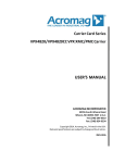
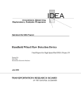
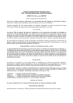
Nameplate Label
Figure 1.2 depicts a typical Bulletin 161 Nameplate Label.
Figure 1.2 Bulletin 161 Nameplate Label
Series
Letter
Catalog Number
161S-AA01NPK
I V: 200-240 1Ø (3Ø)
N A: 3.1(1.8)
P
U Hz:50/60
T
VA: 500
S/N:
82TT1362281161
Allen-Bradley
Serial Number
SERIESB
O V: 200-230 3Ø
U
T A: 1.4
P
U Hz:0.5-360
T Motor
FRN:2.001
POWERTERMINAL
WIRE
Use 75°C CuWire
2.1- 0.75m
m2 (14-18AWG)
Torque 0.9 Nm (8 in.-lbs.)
0.2 kW / 0.3 HP
IP20
MADE INAP
J AN
Rating:
Date:
Enclosure Rating
9927
NE16452-2
Firmware
Version
3
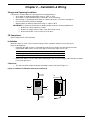
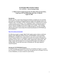
Getting Started
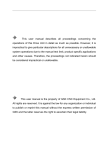
Drive Features
Fixed keypad
Control terminal block cover
Screw
RS422 serial interface
Enclosure
Heat sink
Front case
Control terminal block
Screw
To wire the power terminals
and fault relay, loosen the
screw and open the front
case.
Note that for ratings AA01AA03 the screw is located
under the control terminal
block cover.
Protective earth ground
connection
Debris
cover
Fault relay terminals
RS422 serial interface
Terminal cover
Power terminal block
4
Chapter 2 – Installation & Wiring
Storage and Operating Conditions
Follow these recommendations to prolong drive life and performance:
• Store within an ambient temperature range of –25oC to 70oC.
• Store within a relative humidity range of 20 to 90%, non-condensing.
• Avoid storing or operating the drive where it could be exposed to a corrosive atmosphere.
• Protect from moisture and direct sunlight.
• Operate within an ambient temperature range of –10oC to 40oC.
IMPORTANT: To operate the drive between 40oC and 50oC, make the following adjustments:
➢ Reduce the carrier frequency to 2kHz
➢ Reduce the output current to 80% of the drives rated current
➢ Remove the debris cover from the top of the drive
CE Compliance
Refer to Appendix A – CE Conformity.
Installation
Mount the drives on a flat, vertical and level surface. Drive orientation must be vertical (top up) for
proper heat dissipation.
• Install the drive with screws, recommended screw sizes are listed in the table below. Note that
ratings AA01-AA03 require screws at the upper left and lower right corners only.
Description
Mounting Torque
Mounting Base Screws
•
Metric
1.2 – 1.3 Nm
M4 x 0.7
English
10.6 – 11.5 lb.in.
#8-32
Ensure that debris cover is in place when installing the drive to prevent filings, cable insulation and dust
from entering the drive.
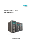
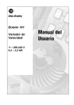
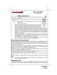
Clearances
•
The drive should be installed using the minimum clearances shown in Figure 2.1.
Figure 2.1 Bulletin 161 Minimum Clearances and Airflow
100 mm
(3.94 in)
30 mm
(1.18 in)
Air
Circulation
30 mm
(1.18 in)
100 mm
(3.94 in)
5
Installation & Wiring
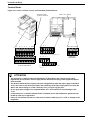
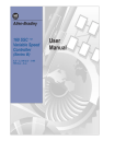
Terminal Blocks
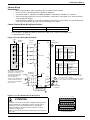
Figure 2.2 Location of Power, Control, and Fault Relay Terminal Blocks
Front cover opened
Protective earth
ground connection
L
5
4
3
2
1 P24
*
+1 +
–
*
*
AL0 AL1 AL2
L1 L2 N/L3 U/T1 V/T2 W/T3
Power terminal block, AA01 - AA03 ratings only
(/) +1 +
H
O 0I L FM CM2 12 11
Control terminal block
–
Fault relay
terminal block
L1 L2 N/L3 U/T1 V/T2 W/T3
Power terminal block, all ratings except AA01 - AA03
* Not Used
ATTENTION
• The installation, commissioning and maintenance of these drives may only be carried out by
experienced personnel who are thoroughly familiar with the functioning of the equipment and the
entire machine.
• The devices feature DC-bus capacitors that are energized even when the input supply is switched
off. For this reason wait at least 5 minutes after switching off the input supply before you open the
device and start working on it. Take care that you do not touch any live parts.
• Do not apply input voltage to the output terminals U/T1, V/T2 and W/T3 as drive damage could
occur.
• Contact the motor or machine manufacturers if standard motors with frequencies greater than 60
Hz will be used in your application.
• Failure to follow these precautions could result in severe bodily injury, loss of life or damage to the
equipment.
6
Installation & Wiring
Power Wiring
Precautions:
ATTENTION
• Ensure that the input voltage corresponds to the voltage indicated on the product nameplate.
• In normal operation apply the START/STOP commands via the control terminals or the control
panel and not by disconnecting and reapplying input power to the drive or motor contactor. If it
is necessary to use this method for starting and stopping, or if frequent cycling of power is
unavoidable, make certain it does not occur more than once every 5 minutes. Do not install any
capacitors or suppressors to the drive output terminals.
• Exercise particular caution if automatic restart is activated. To prevent injuries caused by
automatic restarting of the drive following a power failure, install a switching component at the input
that is deactivated in the event of a power failure and that may only be manually switched
on again on return of the power supply (e.g. contactor etc.).
• Suitable for use on a circuit capable of delivering not more than 5,000 rms symmetrical amperes,
240V maximum.
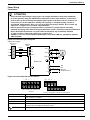
Figure 2.3 Power wiring block diagram
Input power supply
Disconnect
Device
Optional
Filter
Fuses
L1
U/T1
L2
V/T2
3
N/L3
Motor
W/T3
Bulletin 161
–
DC
Bus
Optional
DC Bus Reactor1
+
+1
Figure 2.4 Power terminal block descriptions
*
+1 +
–
*
*
L1 L2 N/L3 U/T1 V/T2 W/T3
AA01 - AA03 Power terminal block
* Not Used
Terminal
L1, L2, N/L3
U/T1, V/T2, W/T3
-/+
+1
+
(/) +1 +
–
L1 L2 N/L3 U/T1 V/T2 W/T3
All ratings except AA01 - AA03 Power terminal block
Description
Connection to incoming power. For single phase input applications, connect the AC input power to
input terminals L1 and N/L3
Motor connections
DC Bus connection
These terminals are connected by a jumper. For applications requiring a DC bus reactor, remove
the jumper prior to installing the third party device.
Protective earth ground connection
1 DC Bus Reactor would be used to assist in limiting harmonic distortion from the 161 to the line and reducing capacitive heating due to low impedance lines.
7
Installation & Wiring
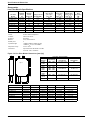
Power Terminal Block Wiring Specifications
Model
AA01-AA02
AA03
AA04, DA01
AA05-AA10, DA02-DA03
AA15
Screw Size
M3.5
M3.5
M4
M4
M4
Max/Min Wire Size mm2(AWG)
2.1 – .75 (14-18)
2.1 – 1.3 (14-16)
5.3 – 1.3 (10-16)
5.3 – 2.1 (10-14)
5.3 – 3.3 (10-12)
Max/Min Torque Nm (lbin)
0.9-0.8 (8.0-7.0)
0.9-0.8 (8.0-7.0)
1.3-1.2 (11.5-10.6)
1.3-1.2 (11.5-10.6)
1.3-1.2 (11.5-10.6)
Power Terminal Connection
IMPORTANT:
• Bulletin 161 Drives feature an electronic overload protection to monitor the motor current. In the
case of multi-motor operation, thermal contacts or PTC resistors must be used for each motor.
• In the case of motor lead lengths greater than 50 meters (165 feet), motor reactors should be used.
Branch Circuit Protection Devices
The following table shows the minimum recommended values for the branch circuit protection devices:
Model
AA01
AA02-AA03
AA04-AA05
AA07
AA10
AA15
DA01
DA02
DA04
Fuse Rating (Class CC, J)
1 Ph
3 Ph
10
10
10
10
15
15
20
15
30
20
N/A
30
10
N/A
15
N/A
20
N/A
1 Ph
140M-D8N-C10
140M-D8N-C10
140M-D8N-C16
140M-D8N-C16
140M-D8N-C25
N/A
140M-D8N-C10
140M-D8N-C10
140M-D8N-C16
Bulletin 140
3 Ph
140M-D8N-B40
140M-D8N-B63
140M-D8N-C10
140M-D8N-C16
140M-D8N-C16
140M-D8N-C25
N/A
N/A
N/A
Input Power Conditioning
The drive is suitable for connection to input power within the rated voltage of the drive (see specifications).
The power factor of the input power supply must not exceed .99. Compensation systems must ensure that
over compensation does not occur at any time.
If the drive must be installed in any of the following conditions, an Input Line Reactor must be used:
Input Power Condition
Line has intermittent noise spikes in excess of 2000V
If frequent voltage dips occur
The drive is operated on a generator
Line has power factor correction capacitors
Several drives are linked via a short common power supply bus bar.
Corrective Action
Install 3% impedance Input Line Reactor
Install 3% impedance Input Line Reactor
Install 3% impedance Input Line Reactor
Install 3% impedance Input Line Reactor
Install 3% impedance Input Line Reactor
Grounding
ATTENTION
• The Bulletin 161 has a high leakage current and must be permanently (fixed) hard wired to ground.
Failure to observe this precaution could result in severe bodily injury or loss of life.
Ground the drive. Be sure to separate the drive’s grounding pole from those of other electrical machinery. If
multiple drives are used, make certain grounding connections do not create a loop as shown in Figure 2.5.
Figure 2.5 Suggested 161 Grounding
Bulletin 161
Protective
Earth
Ground
8
Bulletin 161
Bulletin 161
Bulletin 161
Bulletin 161
Protective
Earth
Ground
Bulletin 161
Installation & Wiring
Control Wiring
Requirements
•
•
•
•
Run all signal wiring in either a shielded cable or separate metal conduit.
Do not exceed control wiring length of 20 meters (65.6 feet).
Use Belden 8760 (or equivalent) –18 AWG (0.750mm2), twisted pair, shielded or 3 conductor.
Avoid crossing the power lines or motor lines with the control wires. If they must cross, ensure that they
cross at right (90o) angles.
If using transistor outputs 11 or 12, with an inductive load such as a relay, install a recovery diode parallel
to the relay as shown in Figure 2.6, to prevent damage to the output.
•
Control Terminal Block Wiring Specifications
Max/Min wire size mm2 (AWG)
0.750 – 0.14 (18-28)
Max/Min Torque Nm (in lb)
0.25 - 0.2 (2.21 – 1.77)
Note: 0.75mm2 (18 AWG) wire must be used for the alarm relay. Torque the mounting screw
to: 0.5-0.6 Nm (4.4-5.3 in lb).
Figure 2.6 Control Wiring Block Diagram
24V
External
Power
Internal
Power
P24
1
1
2
2
3
3
4
5
L
IMPORTANT: Only one frequency
source may be connected at a time.
Frequency
If more than one reference is
Reference
connected at the same time, 1-2k Ohm
an undetermined frequency
Pot.
reference will result.
To improve noise immunity, the 0-10V
common (terminal L) must be
connected to ground terminal/
protective earth.
4-20mA
FM
P24
L
11
See Note 2
CM2
4
0-10V
PWM OutPut
V
Factory Default
Setting & Description
Input
"U"
"U" Default
Parm Terminal Default Description
1
C01
22
3 wire fwd/rev
2
C02
20 2
3 wire run
3
C03
21 1
3 wire stop
4
C04
18
reset
5
C05
13
USP
Factory Default
Setting & Description
5
12
L
H
CM2
10V
O
OI
AL0
AL1
Input
"K"
"K" Default
Parm Terminal Default Description
1
C01
0
Run fwd
2
C02
1
Run rev
3
C03
2
Preset input 1 (CF1)
4
C04
3
Preset input 2 (CF2)
5
C05
13
USP
Notes: 1. Parameter C13 is NC. This input must be active
(jumpered) for the drive to run. See following pages
for description of these settings.
~
2. A contact closure on terminals 3 and P24 is required
for the controller to respond to a Start/Run command.
L
AL2
Fault Relay
230V AC
Figure 2.7 Control terminal block descriptions
L
5
4
3
2
1 P24
ATTENTION
A hazard of electrical shock, death or equipment damage exists.
Control terminals are isolated but not tied to earth ground. If
terminal (L) on the control terminal block is not grounded,
exposed conductors, shields or metal conductors can be at
hazardous voltage levels.
Failure to observe this precaution could result in severe injury or
loss of life.
H
O 0I L FM CM2 12 11
Control Terminal Block
9
Installation & Wiring
Control Terminal Descriptions
ATTENTION
• DO NOT jumper or short circuit terminals H and L or P24 and L or drive damage could occur.
The following table gives a description of each of the terminals on the control terminal block as well as
the fault relay:
Control
Terminal
P24
1
2
Function
24 V DC
Programmable Digital
Inputs.
26V max, 5KΩ input
impedance.
3
4
5
L
H
O
OI
L
FM
0V
10 V Reference Voltage for
Analog Frequency
Command
Voltage Analog Input
Frequency Command
(0-10V)
Current Analog Input
Frequency Command
(4-20 mA)
0 V Reference Potential for
Frequency Command Inputs
Programmable Analog
Output
Analog or Pulse Output
Frequency or Motor Current
Description
24 V potential for digital inputs 1-5 max. load 30mA
Digital inputs 1 – 5 are fully programmable level triggered inputs
via parameters C01 thru C05. These inputs are level triggered. An
overview of the possible functions can be found in the digital input
description table in Chapter 2.
The inputs are fully programmable with these exceptions:
1. No two inputs can have the same function
2. Only input 5 can be programmed as PTC.
3. With the exception of the reset setting which must be
NO (active high), all of the inputs can be set as NO
(active high) or NC (active open) via PC11-[Digital
Input 1 Logic] - PC15-[Digital Input 5 Logic].
Note: A signal must be applied to the digital inputs for at least 12 ms
0 V potential for output FM
Potentiometer
1 to 2 kOhm
0-9.6 V
nominal 0-10 V
H
H
+
O
4-19.6 mA
nominal 0-20 mA
H
O
Input impedance
OI 10 kOhm
OI
L
L
-
PE
+
-
PE
O
Input impedance
OI 250 Ohm
L
PE
Input OI for 4-20mA is activated when one of the digital inputs is
set to 16{AT} via PC01-[Digital Input 1] – PC05-[Digital Input 5]
The analog input reference can be adjusted using PA11-[Analog
Frequency Minimum] – PA16-[Analog Filter Select].
If no digital input is programmed as 16{AT}, the set values are the
sum of O and OI.
This output can be used to monitor the output frequency of the
drive (either Analog or Pulse) or the motor current. This output is
programmable using PC23-[Output FM].
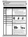
Analog Signal
Frequency or Current
Pulse Signal (50% duty cycle)
Frequency only
t
10 V
10 V
s
T
T=4ms (constant)
s
T
T = (Variable)
Analog Signal: The relation t/T (duty cycle) changes
proportionally with the frequency or current. The maximum
voltage of 10V (100% duty cycle) is reached when the maximum
frequency or 200% of the rated current is reached. Pb81 [Output FM Factor] may be used as a scaling factor.
Accuracy: +/- 5% for frequency , +/- 20% for current
Pulse Signal: Frequency = output frequency x Pb86-[Process
Display Scale Factor], but the maximum frequency is 3.6 kHz (ex.
Freq = 60Hz x 60 = 3.6kHz).
10
Installation & Wiring
Control
Terminal
CM2
Function
Reference potential for
outputs 11 and 12
Description
Transistor output, max. 27 Vdc, 50 mA
11,12
CM2
12
Programmable Digital
Output
11
Programmable Digital
Output
AL0
Fault Relay
–
24V
+
The outputs can be programmed as either NO (active high) or
NC (active open) contacts using PC31-[Digital Output 11Logic]
and PC32-[Digital Output 12 Logic].
The following 6 settings may be programmed using PC21 - [Digital
Output 11] and PC22-[Digital Output 12]:
00{RUN} = Motor Running (Signal if output frequency > 0.5 Hz)
01{FA1} = At frequency (Signal when the set frequency is
reached and that frequency is > 0.5Hz)
02{FA2} = Above frequency (Signal if output frequencies > the
frequencies set under PC42-[Above Frequency Accel
Setting] or PC43-[Above Frequency Decel Setting] and >
0.5 Hz).
03{OL} = Motor overload (Signal if the motor current exceeds
the value set under PC41-[Overload Alarm Setting]
04{OD} = PID-deviation (Signal if the deviation between the
set value and the actual value returned is greater than the
value set under PC44-[PID Deviation Setting]). Only available
if the PID control PA71 –[PID Enable] is active.
05{AL} = Fault (Signal if a fault is indicated)
AL0
230V AC
250 VAC, 2.5 A resistive
0.2A inductive
AL1
30 VDC, 3.0A resistive
0.7A inductive
AL2
min. 100 VAC, 10mA
5 VDC 100 mA
AL1
Faulted / De-energized State
AL2
PC33-[Fault Relay AL1 Logic] can be used to invert the
operation.
PC33
AL0 – AL1
AL0 – AL2
PC33 = 01
Open when Faulted
Open when Power Off
Closed when Faulted
Closed when power off
PC33 = 00
Closed when faulted
Open when Power Off
Open when Faulted
Closed when Power Off
The fault relay is set with a time delay of approximately 2s after
the power is switched on.
11
Installation & Wiring
Programmable Digital Input (Control terminal block inputs 1 through 5) Functions
The function of the digital inputs 1 through 5 are programmed via the corresponding PC01 [Digital Input 1]
through PC05 - [Digital Input 5]. The following programming guidelines must be followed:
• No two inputs can be programmed for the same function.
• The PTC input (setting 19) is only programmable on input terminal 5.
The digital inputs can be programmed to respond to NO (Active High) or NC (Active Open) inputs via
PC11 - [Digital Input 1 Logic] through PC15 - [Digital Input 5 Logic].
ATTENTION
•
•
•
All digital inputs respond to level sensitive commands.
Inputs do not require a voltage transition (cycle) after a fault condition is cleared, after input power cycling or after
programming the logic of the digital input.
All digital inputs can be programmed as NO or NC. HOWEVER, THE START COMMAND SHOULD BE SET AS NO
(ACTIVE HIGH) AND THE STOP COMMAND SHOULD BE SET AS NC (ACTIVE OPEN). If set opposite of this, an
inadvertent start or failure to stop could occur should a discrete connection be lost or control wire come loose. IF THE
USER CHOOSES TO DISREGARD THIS SAFETY PRACTICE – THE RISK ASSUMED BY THE USER CAN BE
REDUCED BY ASSURING THAT OTHER SAFEGUARDS ARE USED TO INSURE PROPER START AND STOP
OPERATION. Depending on the application: This may include appropriate emergency stops, redundant wiring,
electronic guards and/or mechanical guards.
Failure to observe this precaution could result in severe bodily injury or loss of life.
C01 - C05
Setting
00
01
Alpha
Setting
{FW}
{RV}
Function
Description
Forward
Reverse
2-Wire (maintained) Run Forward/Run Reverse settings.
00{FW}(N.O.)
01{RV}(N.O.)
Motor Speed
02
{CF1}
Preset
frequency input
The preset frequencies may be programmed in two ways:
1.
By programming desired preset frequency values via PA21[Preset Frequency 1] through PA35-[Preset Frequency 15].
2.
By selecting the corresponding digital input setting and entering the desired frequency via PF01-[Frequency Command].
03
{CF2}
Preset
frequency input
04
{CF3}
Preset
frequency input
Setting
Input
02
03
CF1
CF2
Preset
frequency input
04
05
CF3
CF4
05
06
{CF4}
{JG}
Jog
1
ON
2
3
4
ON
ON ON
5
ON
6
Preset Speed
7
8
9 10
ON
ON ON
ON ON ON ON
ON
11
ON
ON ON
12
13
14
ON
ON
ON ON
15
ON ON ON ON
ON ON ON ON ON ON ON ON
Note: If any preset frequency input is active, all other frequency commands
will be ignored.
When this input is active, the 00{FW} or 01{RV} inputs will
respond to the frequency programmed via PA38-[Jog Frequency].
The accel ramp is NOT active.
The stop command is determined by PA39-[Jog Stop Mode].
Note: The Jog command will not work with 3-wire control.
Input 06 {JG} (NO)
Run Cmd (NO)
Motor Speed
09
12
{2CH}
2nd Accel/Decel
ramp
2nd Accel/Decel ramp times are activated via this input and
programmed via PA92-[Accel Time 2] and PA93-[Decel Time 2].
Installation & Wiring
C01 - C05
Setting
11
Alpha
Setting
{FRS}
Function
Description
Coast to Stop
The motor voltage will be switched off immediately and the motor
will coast. This function can be programmed to operate in two
different modes via Pb88-[FRS Select].
synchronization of
motor speed
0Hz start
Run (NO)
Input 11 {FRS} (NO)
Motor speed
Waiting time
Note: The drive will start when 11 {FRS} input is removed without
reissuing a start command even if in 3 wire (momentary) control.
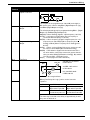
12
{EXT}
External Fault
When this input is active, an E12 fault indication will be issued
(e.g. an input received from thermal contacts). The fault
indication will be cleared with a reset 18{RS}.
Important: After a reset 18{RS} command, the drive will start
again if a start command is active (00{FW}, 01{RV},or 20{STA}).
Run (NO)
Motor will
Coast
Input 12 {EXT} (NO)
Motor Speed
Input 18 {RS} (NO)
Fault relay (ALO-AI2) (NO)
13
{USP}
Unintentional
Start Protection
on Power Up
This function is designed to guard against unintended starting
when input power is removed and then restored. In this case,
if a start/run command is issued immediately upon/after power
is restored an E13 fault will be issued. A new start command
or a reset 18{RS} command will clear the fault indication.
Power Supply
00{FW} or
01 {RV} (N.O.)
13 {USP}(N.C.)
Fault relay (N.O.)
Motor Speed
15
{SFT}
Program Lock
16
{AT}
4-20mA Select
Min. 3 Sec
Protects stored parameter values from being overwritten. See
Pb31-[Program Lock Select] for the 4 different levels of protection.
Activates input terminal OI for use as a 4-20mA input. If no
input terminal is programmed for this setting, the factory
default input is O (0-10V) and the output frequency will
correspond to the value of the inputs to the O and/or OI control
inputs.
Note: PA01-[Frequency Command Select] determines from
what source the output frequency is commanded.
13
Installation & Wiring
C01 - C05
Setting
18
Alpha
Setting
{RS}
Function
Description
Reset
Used to clear a fault condition. If a 18 {RS} command is given
during operation, the output IGBT’s are switched off and the
motor will coast.
min 12 ms
18 {RS} (NO)
Fault indication
19
{PTC}
PTC Input
ca. 30 ms
This input can only be programmed to digital input terminal 5
and the PTC should be referenced to terminal L.
If the PTC resistance exceeds 3k Ohms the output voltage to the
motor will be switched off and an E35 fault code will be issued.
5
L
20
{STA}
3 wire run
21
{STP}
3 wire stop
3-Wire (Momentary) control inputs. Both settings 20 {STA} and
21 {STP} must be programmed as digital inputs for 3-wire control
to function. If 20 {STA} is programmed into any digital input then
2-wire (maintained) control will not function.
Note: 3-wire stop command (21 {STP}) cannot be used to clear a
fault.
20{STA} (NO)
22
{F/R}
3 wire Forward/
Reverse
21{STA} (NC)
22 {FR} (NO)
Motor Speed
27
{UP}
Remote Control
UP
28
{DWN}
Remote Control
DOWN
These settings allow digital inputs to increase and decrease
the commanded frequency for the drive. PA01-[Frequency
Command Select] must be set to 02 to activate this function.
These inputs will change the value of PF01-[Frequency
Command] in Hz/Sec as defined by PA04-[Maximum
Frequency] ÷ (Accel time or Decel time).
RUN (NO)
27 {UP} (NO)
28 {DWN} (NO)
PF01[Freq. Command]
Motor Speed
31
{OPE}
Run
Command
Source Select
This setting is used to determine the source of the Run
commands.
Inactive
Active
14
Start command will come from the control terminals only,
regardless of the setting of PA02 - [Start Command Select]
Start command will come from the start key on the keypad only
regardless of the setting of PA02 - [Start Command Select]
Chapter 3 – Parameters & Programming
ATTENTION
Wait at least 6 seconds after programming the Bulletin 161 before issuing a start, reset command, or
switching off the power supply. Failure to wait 6 seconds, could result in failure to recognize programming
changes, which could lead to bodily injury or damage to the equipment.
Programming Keypad
The keypad is located on the front panel of the drive. This is an integrated keypad that can be used to monitor
drive operation, program parameters, and operate the drive. See page 17 for details on controlling the start, stop
& speed reference from the keypad.
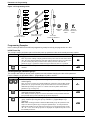
Keypad Features
Keypad Functions
Min
Max
Other Functions
The SELect key is a dual purpose key. It is used to
view parameter groups and to switch between
parameter numbers and values. The SELect key
also acts as an Escape key to exit the parameter
values without changing them.
The PRG LED will be lit when a
programmable parameter is displayed.
The Up/Down Arrow keys are used to scroll
through parameters, or to increase and decrease
parameter values.
The Hz and A LEDs are used to inform you
whether Hz or Amps are being displayed.
The ENTER key is used to enter the current value
into memory.
The RUN LED will be lit when the drive is in
operation.
The Start key can be activated using PA02-[Start
Command Select] or digital input setting 31{OPE}.
When active, the key will start the motor in the
direction of rotation defined in PF04-[Start Key
Direction].
NOTE: If the drive is set for 3 wire control (C03 set
to 21), the Stop Input must be jumpered for the
drive to run.
The Start Key and Speed Pot LED’s are
green LED’s which will light when the item is
active.
The Speed Potentiometer can be used to set the
commanded frequency. This can be activated using
PA01-[Frequency Command Select].
The Stop key is used to stop the motor. If the drive
has stopped due to a fault, pressing this key will
clear the fault.
ATTENTION: If the Stop Key is
used to clear a fault and there is a valid run
command, the drive will start to run as soon
as the fault is cleared without cycling the run input.
Failure to observe this precaution
could result in severe bodily injury.
Figure 3.1 Operator Interface
Programming Keypad
15
Parameters & Programming
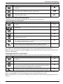
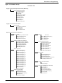
Figure 3.2 Programming Guide
d01
A01
d09
A98
F01
b01
F04
b89
C01
A ..
B ..
C91
C ..
Scroll Thru
Parameter Groups
Press SEL to enter
parameter group.
View
Save
Parameter Change
Entered
Value
Parameter Parameter
Value
Value
Scroll Thru
Parameter Numbers
Programming Examples
In this section you will find four different programming examples to help you program the 161 drive.
Initial Power Up
This example shows you how to proceed from the power up parameter value to the actual parameter number.
Action
Description
1. Apply power to the Drive
Display
Note: If you were viewing a display parameter when power was last removed from the
drive, the same display parameter value will reappear when the drive is re-powered. If
you were viewing any other parameter value when power was removed, the
parameter group or parameter number will appear when the drive is re-powered.
2.
0.0
Press the SELect Key to switch from the parameter value to the parameter
number.
d 01
Scrolling through parameter groups
This example will show you how to check a parameter value without changing the value of the parameter.
For this example, the operation of PC21 - [Digital Output 11] will be verified.
Action
Description
3. Press the Up/Down keys to scroll through the parameter groups, stopping
at the C group.
Note: You must scroll thru all of the d and F group parameters, but the A, b, and C
parameters are grouped and the group must be SELected to view the parameters
within that specified group. Figure 3.3 contains a hierarchy which details which
parameters are in each group.
4.
Press the SELect Key to enter into the C group. PC01 - [Digital Input 1]
should appear on the display.
Note: When parameter groups are entered, the number of the parameter that was
being viewed when you last exited the group will be displayed.
5.
C--
C 01
Press the Up Key to scroll through the parameters contained within the
group, continue pressing the Up Key until PC21 - [Digital Output 11] is
displayed.
Note: When viewing parameters within the A, b and C groups the parameters will
wrap from A01 through C91 by pressing the Up/Down Keys. To view parameters
within the d and F groups the SELect Key must be pressed until the display shows
A - -, b - - or C- -. Once the group letter is displayed, the Up/Down Key will scroll to
the d and F parameters.
16
Display
C 21
Parameters & Programming
Action
Description
6. Press the SELect Key to view the parameter value stored in PC21 - [Digital
Output 11].
Display
01
7.
Press the SELect Key again to exit from the parameter value back to the
parameter number without changing the stored value.
C 21
8.
Press the SELect Key again to exit from the parameter number to the
parameter group display.
C--
Operation of the Drive via the Fixed Keypad
The following steps demonstrate configuring the drive for operation from the keypad.
Activate the Start Key on the Keypad.
Action
Description
9. Press the SELect Key to switch from the parameter value to the parameter
number.
Display
d 01
10. Press the Up/Down Keys to scroll through the parameter groups stopping at
the A group.
A --
11. Press the SELect Key to enter into the A group.
A 01
12. Press the Up Key to display PA02 - [Start Command Select].
A02
13. Press the SELect Key to view the parameter value stored in parameter A02 [Start Command Select].
01
14. Use the Up Key to change the value of PA02 - [Start Command Select] from
the default value of 01 to 02. This will switch the source of the start input from
the control terminal block to the keypad.
15. When the desired value is displayed, press the Enter Key. This writes the new
value to memory and the display will return to the parameter number.
02
A02
Note: The green LED above the Start key will be illuminated when the Start key is active.
Note: The factory default settings for the “U” version drive is three wire control (PC03 is set to 21 and C13 is set to
01). A jumper is required between terminals P24 and 3 on the control terminal block for the drive to run.
Note: The direction of rotation is controlled by PF04 - [Start Key Direction]. Refer to page 22 of the User Manual for
parameter setting options.
Activating the Speed Pot on the Keypad
Parameter A01-[Frequency Command Select] is used to select the source of the frequency command.
Action
Description
Display
16. Press the Down Key until PA01 - [Frequency Command Select] is
A01
displayed.
17. Press the SELect key to view the parameter value.
01
18. Use the Down Key to change the value of PA01 - [Frequency Command
Select] from the default value of 01 to 00. This will switch the source of the
frequency command to the potentiometer on the keypad.
19. When the desired value is displayed, press the Enter Key. This writes the
new value to memory and the display will return to the parameter number.
00
A01
Note: The output frequency of the Bulletin 161 can also be controlled digitally from the keypad by setting PA01 to setting 02, then using PF01-[Frequency Command] to change to output frequency of the drive.
Note: If a digital input is set as 27 (UP) or 28 (DWN), when activated these inputs will also change the frequency of
the drive.
17
Parameters & Programming
Restoring Factory Defaults
This example will show you how to reset the factory defaults of the drive.
Action
Description
20. Press the Down Key to advance to the b parameter group.
Display
b--
21. Press the SELect key to enter into the b parameter group.
b 01
22. Press the Up Key to scroll through the parameters until parameter b84 [Reset Functions] is displayed.
b 84
23. Press the SELect Key to view the parameter value stored in parameter b84 [Reset Functions] and verify that it is set to 01. If it is not 01, use the UP key to
change the value to 01, then press the Enter key.
01
Note: The defaults will be reset to the values determined by parameter b85 Factory Default Select].
+
24. Press the SELect Key to exit the parameter value back to the parameter
number without changing the stored value.
b 84
25. Press and hold the SELect, Up, Down and Stop Keys for 3 seconds.
NOTE: The keys can be pressed and held in any sequence, but the Stop Key
MUST be the last key held.
b 84
+
+
18
26. Release the Stop Key and continue to hold the SELect, Up and Down Keys
until the display begins to blink. Release the remaining keys. When this is
done, 0.0 will be displayed (this is parameter d01 - [Output Frequency]).
00 ”Blinking”
0.0
Parameters & Programming
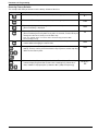
Figure 3.3 Parameter Groups
Parameter Tree
d group - Display and Diagnostic Parameters (Read only)
Display & Diagnostic Functions
d01 Output Frequency
d02 Output Current
d03 Direction
d04 PID Process Display
d05 Digital Input Status
d06 Output Status
d07 Process Display
d08 Last Fault
d09 Fault Register
d16 Elapsed Run Time
F group - Basic Function Parameters
Basic Functions
F01 Frequency Command
F02 Accel Time 1
F03 Decel Time 1
F04 Start Key Direction
A group - Advanced Function Parameters
Basic Functions
A01 Frequency Command Select
A02 Start Command Select
A03 Base Frequency
A04 Maximum Frequency
Analog Input Reference Adjustment
A11 Analog Frequency Minimum
A12 Analog Frequency Maximum
A13 Analog Input Minimum
A14 Analog Input Maximum
A15 Analog Start Select
A16 Analog Filter Select
Preset Frequencies
A20 Internal Frequency
A21 Preset Frequency 1
A22 Preset Frequency 2
A23 Preset Frequency 3
A24 Preset Frequency 4
A25 Preset Frequency 5
A26 Preset Frequency 6
A27 Preset Frequency 7
A28 Preset Frequency 8
A29 Preset Frequency 9
A30 Preset Frequency 10
A31 Preset Frequency 11
A32 Preset Frequency 12
A33 Preset Frequency 13
A34 Preset Frequency 14
A35 Preset Frequency 15
A38 Jog Frequency
A39 Jog Stop Mode
V/F Characteristics/Boost
A41 Boost Select
A42 Manual Boost Voltage
A43 Manual Boost Frequency
A44 V/Hz Select
A45 Maximum Voltage
DC Brake
A51 DC Brake Select
A52 DC Brake Start Frequency
A53 DC Wait Time
A54 DC Hold Voltage
A55 DC Hold Time
Operating Frequency Range
A61 Upper Frequency Limit
A62 Minimum Frequency
A63 Skip Frequency 1
A64 Skip Frequency Band 1
A65 Skip Frequency 2
A66 Skip Frequency Band 2
A67 Skip Frequency 3
A68 Skip Frequency Band 3
PID Controller
A71 PID Enable
A72 PID Proportional Gain
A73 PID Integral Gain
A74 PID Differential Gain
A75 Process Reference Scale Factor
A76 Analog Feedback Select
Automatic Voltage Regulation
A81 AVR Function Select
A82 Base Voltage
Second Acceleration/Deceleration Ramp
A92 Accel Time 2
A93 Decel Time 2
A94 Accel/Decel 2 Select
A95 Accel 2 Start Frequency
A96 Decel 2 Start Frequency
A97 Accel Curve
A98 Decel Curve
19
Parameters & Programming
Parameter Tree cont.
b Group - Advanced Control and Protection
Automatic Start After a Fault
b01 Restart Mode Select
b02 Power Loss Time
b03 Restart Time
Electronic Motor Protection
b12 Motor Overload Current
b13 Motor Overload Select
Current Limit
b21 Current Limit Select
b22 Current Limit
b23 Current Limit Decel Time
Parameter Protection
b31 Program Lock Select
Current Feedback Tuning
b32 Relative Current Setting
Initialization/Adjustment Function
b81 Output FM Adjustment
b82 Start Frequency
b83 PWM Frequency
b84 Reset Functions
b85 Factory Default Select
b86 Process Display Scale Factor
b87 STOP Key select
b88 FRS Select
b89 Keypad Display
b92 Reserved
C group - Intelligent I/O and Communication
Digital Inputs 1-5
C01 Digital Input 1
C02 Digital Input 2
C03 Digital Input 3
C04 Digital Input 4
C05 Digital Input 5
C11 Digital Input 1 Logic
C12 Digital Input 2 Logic
C13 Digital Input 3 Logic
C14 Digital Input 4 Logic
C15 Digital Input 5 Logic
Outputs 11, 12, FM, AL0 - AL1
C21 Digital Output 11
C22 Digital Output 12
C23 Output FM Select
C31 Digital Output 11 Logic
C32 Digital Output 12 Logic
C33 Fault Relay AL1 Logic
C41 Overload Alarm Threshold
C42 Above Frequency Accel Threshold
C43 Above Frequency Decel Threshold
C44 PID Deviation Threshold
Communications
C70 Communication Command Select
C71 Unassigned
C72 Unassigned
C79 Communication Error Select
C91 Debug Mode
20
Parameters & Programming
Parameter Descriptions
D Group - Display and Diagnostic Parameters (Read Only)
This group of parameters consists of commonly viewed drive operation conditions such as output
frequency. All parameters in this group are Read Only.
Parameter Parameter Name / Description
Number
Display and Diagnostic Functions
d01
[Output Frequency]
Displays the output frequency to the motor.
d02
[Output Current]
Displays the output current to the motor.
d03
[Direction]
Displays the present direction of rotation.
F=Forward
r=Reverse
o=Stop
d04
[PID Process Display]
Displays the scaled PID Process variable (feedback), this is
only available when the PID control is active. The scale factor
is set using parameter C15 - [Digital Input 5 Logic].
d05
[Digital Input Status]
Displays the status of the 5 digital inputs regardless of how
each input is programmed in parameter C11 - [Digital Input 1
Logic] through parameter C15 - [Digital Input 5 Logic].
54321
d06
Min./Max
Range
Units
0.0/360.0
0.1 Hz
0.00/
999.9
Alpha
Numeric
Value
0.01A
0/100.0
0.01%
N/A
N/A
N/A
N/A
0.00/9999
0.01
N/A
---
N/A
---
0/9999
10
hours
Alpha
Numeric
Value
Active
Inactive
[Output Status]
Displays the status of the digital outputs and the fault
indication relays.
AL12 11
Active
Inactive
d07
d08
d09
d16
[Process Display]
Displays parameter d01 - [Output Frequency ] scaled by the
variable set in parameter b86 - [Process Display Scale Factor].
Note: If there are more than 4 digits, the LSB will be dropped.
[Last Fault]
Displays the last fault. The output frequency, motor current,
and DC-bus voltage at the time of the last fault can be viewed
by pressing the SELect key. If there has not been a fault or the
register has been cleared, then --- will be displayed.
[Fault Register]
Displays the 2nd and 3rd fault, if there are no faults stored in
this register, then --- will be displayed. To view the 3rd fault,
press the SELect key.
[Elapsed Run Time]
Displays the elapsed running time of the drive. The elapsed
running time is the displayed value x 10.
21
Parameters & Programming
F Group – Basic Function Parameters
Parameter
Number
Parameter Name / Description
Basic Functions
F01
[Frequency Command]
When parameter A01- [Frequency Command Select]
is set to 00 or 01, this parameter will display the
commanded frequency. When PA01 - [Frequency
Command Select] is set to 02, this parameter can
be used to change the commanded frequency on
the fly and write the value into parameter A20 [Internal Frequency]. When a preset frequency is
active, this parameter can be used to program or
change the value of the preset input on the fly while
writing the value into the corresponding parameter
(PA21 - [Preset Frequency 1] – PA35 - [Preset
Frequency 15]).
Note: The value Is changed in real time and written to memory
without using the Enter key.
This parameter can be changed while motor is running.
F02
[Accel Time 1]
Time for the drive to ramp from 0.0 Hz to PA04 [Maximum Frequency]
This parameter can be changed while motor is running.
F03
[Decel Time 1]
Time for the drive to ramp from PA04 - [Maximum
Frequency] to 0.0 Hz
This parameter can be changed while motor is running.
F04
[Start Key Direction]
Sets the direction of motor rotation when the drive
is set to Start Key mode, which is controlled by
PA02 - [Start Command Select] and digital input
setting 31 {OPE}.
Settings: 00=Forward
01=Reverse
02=Control Terminal – Digital inputs
(C01-C05) settings 00 {FW} and 01 {RV}
determine direction of Start Key.
Min./Max
Range
Units
Factory
Defaults
U1
N/A
K1
N/A
0.0/360.0
0.1 Hz
0.1/3000
<1000, 0.1 s
>1000, 1 s
10.0
10.0
0.1/3000
<1000, 0.1 s
>1000, 1 s
10.0
10.0
00/02
Numeric Value
00
0.0
A Group – Advanced Function Parameters
Parameter
Number
Parameter Name / Description
Basic Functions
A01
[Frequency Command Select]
Selects the source of the frequency command for
the drive. Note: If any preset frequency inputs are active, all
other frequency commands will be ignored.
Settings: 00= Keypad frequency potentiometer
01=Input O/OI (Analog reference)
02=Internal frequency (PF01 [Frequency Command]/ PA20 [Internal Frequency])
A02
[Start Command Select]
Selects the source of the start command. Settings:
01=Control terminal block
02=Start Key (Input from Start Key on drive keypad)
Min./Max
Range
Units
00/02
Numeric Value
U1
01
01/02
Numeric Value
01
Note: If PC03 is set to 21, terminals P24 and 3 must be jumpered for drive to run.
1
U = 50Hz default settings, K = 50 Hz default settings. Settable using Pb85 – [Factory Default Select]
22
Factory
Defaults
K1
01
01
Parameters & Programming
Parameter
Number
Parameter Name / Description
Min./Max
Range
Basic Functions
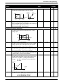
A03
[Base Frequency]
Set value to rated nameplate frequency of motor
Command
Frequency
Voltage
100%
0
Start
Frequency
b82
A04
Base
Frequency
A03
Frequency
Maximum
Frequency
A04
Minimum
Frequency
A62
Units
Factory
Defaults
50/360
1 Hz
U1
60
K1
50
50/360
1Hz
60
50
0.0/360.0
0.1 Hz
U1
0.0
K1
0.0
0.0/360.0
0.1 Hz
0.0
0.0
0/99
1%
0
0
0/100
1%
100
100
00/01
Numeric Value
01
01
1/8
Numeric Value
8
8
Upper
Frequency Limit
A61
Hz
[Maximum Frequency]
Highest frequency the drive will output.
Note: If a maximum frequency less than PA03 – [Base Frequency] is
needed, use PA61 – [Upper Frequency Limit].
Refer to diagram in PA03 – [Base Frequency].
Analog input reference adjustment
A11
[Analog Frequency Minimum]
Sets the frequency that corresponds to a 0V or 4mA
analog signal.
A12
% Input
Scale
A11
0V
4mA
A12
A13
A14
A15
A13
A14
10V
20mA
[Analog Frequency Maximum]
Sets the frequency that corresponds to a 10V or 20mA
analog signal. A value of 0.0 will disable this function.
Refer to diagram in PA11 – [Analog Frequency Minimum].
[Analog Input Minimum]
Sets the starting point (offset) for the analog input range.
Refer to diagram in PA11 - [Analog Frequency Minimum]
[Analog Input Maximum]
The ending point (offset) for the analog input range. Refer
to diagram in PA11 - [Analog Frequency Minimum].
[Analog Start Select]
Sets the output frequency when frequency reference is
below value set in PA13 – [Analog Input Minimum].
Settings: 00 = PA11 - [Analog Frequency Minimum]
01 = 0 Hz
Frequency
A12
A15=00
A11
0V
4mA
A16
A15=01
A13
A14
% Input
Scale
10V
20mA
[Analog Filter Select]
Sets the level of the Analog input smoothing filter where:
1 = low. (Bandwidth = 200 Hz)
8 = high. (Bandwidth = 25 Hz)
23
Parameters & Programming
1
U = 50Hz default settings, K = 50 Hz default settings. Settable using Pb85 – [Factory Default Select]
Parameter
Number
Min./Max
Range
Units
Factory
Defaults
0.0/360.0
0.1 Hz
U1
60.0
0.0/360.0
0.1 Hz
0.0
0.0
0.0/360.0
0.1 Hz
3.0
0.0
0.0/360.0
0.1 Hz
5.0
0.0
0.0/360.0
0.1 Hz
10.0
0.0
0.0/360.0
0.1 Hz
15.0
0.0
0.0/360.0
0.1 Hz
20.0
0.0
0.0/360.0
0.1 Hz
25.0
0.0
0.0/360.0
0.1 Hz
30.0
0.0
0.0/360.0
0.1 Hz
35.0
0.0
0.0/360.0
0.1 Hz
40.0
0.0
[Preset Frequency 11]
0.0/360.0
0.1 Hz
45.0
0.0
A32
[Preset Frequency 12]
0.0/360.0
0.1 Hz
50.0
0.0
A33
[Preset Frequency 13]
0.0/360.0
0.1 Hz
55.0
0.0
A34
[Preset Frequency 14]
0.0/360.0
0.1 Hz
60.0
0.0
A35
[Preset Frequency 15]
0.0/360.0
0.1 Hz
0.0
0.0
A38
[Jog Frequency]
This parameter sets the frequency the drive will
output when it receives a valid jog command.
This Parameter can be changed while motor is running.
[Jog Stop Mode]
This parameter sets the stop method when the jog
input is removed.
Settings:
00=Coast
01=Ramp
02=DC Brake (See PA53 - [DC Wait
Time] – PA55 - [DC Hold Time])
0.5/9.9
0.1 Hz
5.0
5.0
00/02
Numeric
Value
01
01
Pre-Set Frequencies
A20
[Internal Frequency]
When PA01-[Frequency Command Select] is set to
02, this parameter will provide the drives frequency
command. This parameter will change the frequency
command only after the new frequency is entered into
memory.
This value can also be changed via PF01 [Frequency Command] if no preset frequency inputs
are active.
This Parameter can be changed while motor is running.
A21
[Preset Frequency 1]
The programmed value
sets the frequency that
A22
[Preset Frequency 2]
the drive outputs when
selected. (Refer to
A23
[Preset Frequency 3]
digital input settings
table in Chapter 2). Note: If
A24
[Preset Frequency 4]
a preset frequency input is
active, the keypad frequency
A25
[Preset Frequency 5]
pot and analog frequency
commands will be ignored.
A26
[Preset Frequency 6]
Note: The value of any Preset
Frequency can be changed via
A27
[Preset Frequency 7]
PF01 - [Frequency Command]
when the Preset Frequency is
A28
[Preset Frequency 8]
activated via the digital inputs.
These Parameters can be
A29
[Preset Frequency 9]
changed while motor is
A30
[Preset Frequency 10]
running.
A31
A39
1
Parameter Name / Description
U = 60 Hz default settings, K = 50 Hz default settings. Settable using Pb85 – [Factory Default Select]
24
K1
0.0
Parameters & Programming
Parameter
Number
Parameter Name / Description
Min./Max
Range
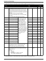
V/F Characteristics / Boost
A41
[Boost Select]
Used to select auto or manual boost
Settings:
00=Manual Boost
01=Auto Boost
A42
[Manual Boost Voltage]
Sets the boost level as a percent of PA82 - [Base
Voltage].
This Parameter can be changed while motor is running.
Voltage
100%
Units
Factory
Defaults
U1
00
K1
00
00/01
Numeric
Value
0/99
Numeric
Value
25
11
0.0/50.0%
0.1%
2.0
10.0
00/01
Numeric
Value
00
00
50/100
1%
100
100
99 ~
= 20%
of Base Voltage at 0Hz,
then linear scale down
e.g. 25 ~
= 5%
A42
A43
30Hz
1/2 Base
frequency
Frequency
60Hz
Base frequency
A43
[Manual Boost Frequency]
Sets the boost frequency point as a percent of PA03 [Base Frequency]. Refer to diagram in PA42 –
[Manual Boost Voltage]
This Parameter can be changed while motor is running.
A44
[V/Hz Select]
Used to select the V/Hz mode.
Settings: 00=Constant Torque
01=Variable Torque
Voltage
100%
0
A45
A44 = 00
Constant
Torque
A44 = 01
Variable
Torque
frequency
Base frequency
[Maximum Voltage Gain]
Sets the voltage gain of the V/Hz characteristic.
Value is a percent of PA82 - [Base Voltage].
This Parameter can be changed while motor is running.
100%
A45
50%
0
1
frequency
Base frequency
U = 60 Hz default settings, K = 50 Hz default settings. Settable using Pb85 – [Factory Default Select]
25
Parameters & Programming
Parameter
Number
DC Brake
A51
A52
A53
A54
A55
Parameter Name / Description
[DC Brake Enable]
Used to enable/disable DC injection braking
Settings: 00=Disabled
01=Enabled
[DC Brake Start Frequency]
Sets the frequency at which the DC brake will
become active.
[DC Brake Wait Time]
Sets the time the drive will wait after PA52 [DC Brake Start Frequency] before applying
PA54 - [DC Hold Voltage].
[DC Hold Voltage]
Sets the level of DC braking voltage in percent
of PA82 - [Base Voltage].
[DC Hold Time]
The time that PA54 -[DC Hold Voltage] is
applied to the motor after PA53 - [DC Brake
Waiting Time] has expired.
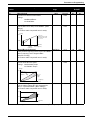
Operating Frequency Range
A61
[Upper Frequency Limit]
This is an upper frequency limit similar to PA04 [Maximum Frequency] except that it can be
set lower than PA03 - [Base Frequency]. A
value of 0.0 will disable this parameter.
Output Frequency
Min./Max
Range
Units
Factory
Defaults
00/01
Numeric Value
U1
00
0.5/10.0
0.1Hz
10.0
10.0
0.0/5.0
0.1 seconds
0.0
0.0
0/100
1% of drive
rating
0
0
0.0/60.0
0.1 seconds
0.0
0.0
0.1Hz
U1
0.0
K1
0.0
0.0
0.0
0.0
0.0
0.5
0.5
0.0
0.0
0.5
0.5
0.5/360.0
K1
00
Output Frequency
A61
A62
Frequency Command
0.0/360.0
0.1Hz
[Minimum Frequency]
Lowest frequency the drive will output
continuously.
Refer to diagram in PA61 – [Upper Frequency Limit].
A63
[Skip Frequency 1]
0.0/360.0
0.1Hz
Sets a frequency at which the drive will not output
continuously.
0.0/10.0
0.1Hz
A64
[Skip Frequency Band 1]
Sets the bandwidth around PA63 -[Skip
Frequency 1]. The bandwidth is 2x PA64 –
[Skip Frequency Band 1] with ½ the band
below and ½ the band above PA63 - [Skip
Frequency 1].
A65
[Skip Frequency 2]
0.0/360.0
0.1Hz
Sets a frequency at which the drive will not output
continuously.
A66
[Skip Frequency Band 2]
0.0/10.0
0.1Hz
Sets the bandwidth around PA65 -[Skip
Frequency 2]. The bandwidth is 2x PA66 [Skip Frequency Band 2] with ½ the band
below and ½ the band above PA65 - [Skip
Frequency 2].
1
U = 60 Hz default settings, K = 50 Hz default settings. Settable using Pb85 – [Factory Default Select]
A62
26
Parameters & Programming
Parameter
Number
Parameter Name / Description
Operating Frequency Range cont.
A67
[Skip Frequency 3]
Sets a frequency at which the drive will not output
continuously.
A68
[Skip Frequency Band 3]
Sets the bandwidth around PA67 - [Skip
Frequency 3]. The bandwidth is 2x PA68 [Skip Frequency Band 3] with ½ the band
below and ½ the band above PA67 - [Skip
Frequency 3].
PID Controller
A71
[PID Enable]
Used to disable / enable the use of PID control.
Settings: 00=disable
01=enable
(See Figure 4.1 for PID block diagram)
A72
[PID Proportional Gain]
Sets the proportional gain for the PID control.
This Parameter can be changed while motor is running.
A73
[PID Integral Gain]
Sets the integral gain for the PID control.
This Parameter can be changed while motor is running.
A74
[PID Differential Gain]
Sets the differential gain for the PID control.
This Parameter can be changed while motor is running.
A75
[Process Reference Scale Factor]
Used to scale the target value equivalent to the
PID feedback value.
A76
[Analog Feedback Select]
Selects the source from which the PID
feedback originates
Settings: 00=Input OI
01=Input O
Automatic Voltage Regulation (AVR)
A81
[AVR Function Select]
Used to select the Automatic Voltage Regulation
function.
Settings: 00=Active
01=Inactive
02=Inactive during deceleration
A82
[Base Voltage]
Set voltage to rated nameplate voltage of motor.
Min./Max
Range
Factory
Defaults
0.0/360.0
0.1Hz
U1
0.0
0.0/10.0
0.1 Hz
0.5
0.5
U1
00
K1
00
K1
0.0
00/01
Numeric
Value
0.2/5.0
N/A
1.0
1.0
0.0/150.0
0.1 seconds
1.0
1.0
0.0/100.0
N/A
0.0
0.0
0.01/99.99
N/A
1.00
1.00
Numeric
Value
00
00
U1
02
K1
02
230
230
U1
15.0
K1
15.0
15.0
15.0
00/01
00/02
200/220/230
/240
Second Acceleration / Deceleration Ramp
A92
[Accel Time 2]
0.1/3000
Time for the drive to ramp from 0.0 Hz to PA04 [Maximum Frequency]. PA94 - [Accel/Decel
2 Select] is used to determine when active.
This Parameter can be changed while motor is running
0.1/3000
A93
[Decel Time 2]
Sets the time for the drive to ramp from PA04 [Maximum Frequency] to 0.0 Hz. PA94 -[Accel/Decel2
Select] is used to determine when active.
This Parameter can be changed while motor is running.
1
Units
Numeric
Value
Volts
<1000, 0.1 s
>1000, 1 s
<1000, 0.1 s
>1000, 1 s
U = 60 Hz default settings, K = 50 Hz default settings. Settable using Pb85 – [Factory Default Select]
27
Parameters & Programming
Parameter
Number
Parameter Name / Description
Min./Max
Range
Operating Frequency Range cont.
A94
[Accel / Decel 2 Select]
Used to determine when the PA92 – [Accel
Time 2] and PA93 - [Decel Time 2] are used.
Settings: 00=Digital inputs (C01-C05) set to 09{2CH}
01=Automatic if frequency
programmed in PA95 - [Accel 2
Start Frequency]/ PA96 - [Decel 2
Start Frequency] is reached.
A95
[Accel 2 Start Frequency]
Sets the frequency at which PA92 - [Accel Time
2] will take effect if PA94 - [Accel/Decel 2
Select] is set to 01.
A96
[Decel 2 Start Frequency]
Sets the frequency at which PA93 - [Decel Time
2] will take effect if PA94 - [Accel/Decel 2
Select] is set to 01.
A97
[Accel Curve]
Selects the type of acceleration curve.
Settings: 00=Linear
01=S-curve
A98
[Decel Curve]
Selects the type of deceleration curve.
Settings: 00=Linear
01=S-curve
Units
00/01
Factory
Defaults
Numeric
Value
U1
00
K1
00
0.0/360.0
0.1 Hz
30.0
0.0
0.0/360.0
0.1 Hz
30.0
0.0
00/01
Numeric
Value
00
00
00/01
Numeric
Value
00
00
Figure 3.4 PID Loop Block Diagram
Frequency
Command
Setting
PF01
Preset
Frequency
Setting
Set point
(Target)
Process Reference
Scale Factor
reciprocal
1/PA75
Process Reference
Scale Factor
Frequency
Command
Select
PA75
PID
Proportional
Gain
PA72
Potentiometer
on keypad
SP
[AT]
Voltage
[O]
PV
Process Variable
(Feedback)
Analog input reference adjustment
A GND
OI
Current
28
PA76
Analog
Feedback
select
PID
Integral
Gain
PA73
E
PA13 PA14
E
Frequency
Setting
PID
Differential
Gain
PA74
PA75
PA11
PA15
Error
Process Reference
Scale Factor
PA12
L
PF01
PA01
PA20 to PA35
V/I input
select
Frequency
Command
PID
Process Display
Pd04
Parameters & Programming
b Group – Advanced Control and Protection Parameters
Parameter
Number
Parameter Name / Description
Min./Max
Range
Automatic Start After a Fault
b01
[Restart Mode Select]
Selects the restart mode for the drive
Settings: 00=Fault indication
01=0 Hz start
02=Synchronize.
03=Synchr. and stop
Note: If set to 01, 02 or 03 the drive will attempt to restart the
following number of times after the following events:
Overcurrent – 3 restarts
Overvoltage – 3 restarts
Undervoltage – 16 restarts (refer to Pb03 – [Restart Time] for time
between restart attempts)
b02
b03
1
ATTENTION: This parameter may only be used as
outlined in NFPA 79, “Under Voltage Protection.”
Equipment damage and/or personal injury may result if this
parameter is used in an inappropriate application.
[Power Loss Time]
If undervoltage exists longer than the
programmed time, the drive will fault even if Pb01 [Restart Mode Select] is active.
[Restart Time]
Sets the time between restart attempts after an
undervoltage fault or the removal of a digital
input set to 11 {FRS}.
Units
Factory
Defaults
U1
00
K1
00
00/03
Numeric Value
0.3/25.0
0.1
seconds
1.0
1.0
0.3/100.0
0.1
seconds
1.0
1.0
U = 60 Hz default settings, K = 50 Hz default settings. Settable using Pb85 – [Factory Default Select]
Parameter
Number
Parameter Name / Description
Min./Max
Range
Electronic Thermal Motor Protection
b12
[Motor Overload Current]
Set to motor nameplate full load amps.
b13
[Motor Overload Select]
Selects the characteristics of the electronic thermal
motor protection.
Settings: 00=Derating1
01=No Derating
02=Derating2
5/120% of
rated
current
00/02
Units
Factory
Defaults
U1
K1
0.01A
115% 115%
of drive of drive
rating rating
Numeric Value
01
01
Torque
b13 = 01
100%
80%
b13 = 02
60%
b13 = 00
5Hz
20Hz
60Hz
Output frequency
120Hz
29
Parameters & Programming
Parameter
Number
Parameter Name / Description
Current Limit
b21
[Current Limit Select]
Selects the mode for current limit.
Settings: 00=Inactive
01=Active
02=Inactive in acceleration
b22
b23
[Current Limit]
Sets the maximum output current allowed before
current limiting occurs. Value set in percent of drive
rated output current.
[Current Limit Decel Time]
Sets the deceleration time when the current limiting
occurs.
Parameter Protection
b31
[Program Lock Select]
Sets the mode of program lock used.
Settings: 00=All parameters locked when digital
input setting 15 {SFT} active.
01=All parameters locked except PF01
– [Frequency Command] when
digital input setting 15 {SFT} active.
02=All parameters locked
03=All parameters locked except PF01
– [Frequency Command].
Current Feedback Tuning
b32
[Reactive Current Setting]
Use to improve accuracy by calibrating drive
motor combination. For improved accuracy,
adjust this value during no load operation until
Pd02 - [Output Current] matches actual motor
current.
Min./Max
Range
00/02
50/150% of
rated current
0.3/30.0
00/03
0.00/100%
Units
U1
01
K1
01
0.01 A
150% of
drive
rating
150% of
drive
rating
0.1 second
1.0
1.0
U1
01
K1
01
U1
40% of
drive
rating2
K1
40% of
drive
rating
Numeric
Value
Numeric
Value
0.01A
1
U = 60 Hz default settings, K = 50 Hz default settings. Settable using Pb85 – [Factory Default Select]
2
5hp (3.7 kW) ratings have a default value of 35%.
30
Factory
Defaults
Parameters & Programming
Parameter
Number
Parameter Name / Description
Initialization / Adjustment Function
b81
[Output FM Adjustment]
Sets the multiplier applied to output duty cycle for the
FM analog signal.
This Parameter can be changed while motor is running.
Min./Max
Range
Units
Factory
Defaults
0/255
N/A
U1
80
K1
80
b82
[Start Frequency]
Sets the frequency at which the drive will start.
Refer to diagram in PA03 – [Base Frequency]
0.5/9.9
0.1 Hz
0.5
0.5
b83
[PWM Frequency]
Carrier frequency for the PWM output waveform.
Output current must be derated by twenty percent
when set above 12 kHz.
0.5/16.0
0.1 kHz
5.0
5.0
b84
00/01
[Reset Functions]
Resets the factory defaults or clears fault history.
Settings: 00=Clear fault history
01=Reset defaults
Note: To activate this parameter, set the value and press the Enter
Key, then hold the SELect, Up, Down, and STOP Keys for 3
seconds, release only the STOP Key until display is blinking, then
release all of the keys.
Note: Defaults will reset to factory settings determined by Pb85 –
[Factory Defaults Select]
Numeric Value
01
00
b85
[Factory Default Select]
06/07
Determines the default settings of all parameters. The
drive will reset to these default values when a “reset
defaults” command is executed as described in Pb84,
setting 01 = reset defaults.
Settings: 06=K (50 Hz default settings)
07=U (60 Hz default settings)
Note: Parameter default values for settings 00 - 05 are not
published in this manual and are not recommended. If using these
default settings Pb87 becomes active. Refer to the Attention
statement under Pb87.
Numeric Value
07
06
b86
[Process Display Scale Factor]
0.1/99.9
Sets the frequency factor for Pd07 –[Process Display].
Also sets the multiplier that is applied to the output
frequency for the FM pulse signal.
This Parameter can be changed while motor is running
N/A
30.0
1.0
b87
[STOP Key Select]
00/01
This parameter is not active when Pb85 is set to setting
06 or 07.
Numeric
Value
00
00
ATTENTION: If Pb85 settings 00 through 05, are activated,
this parameter will control the operation of the keypad STOP key. Setting
00 will enable the STOP key and 01 will disable the STOP key. Disabling
the STOP key is not recommended as it could result in personal injury, loss
of life or equipment damage.
1
U = 60 Hz default settings, K = 50 Hz default settings. Settable using Pb85 – [Factory Default Select]
31
Parameters & Programming
Parameter
Number
Parameter Name / Description
Initialization / Adjustment Function
b88
[FRS Select]
Selects operation of the drive after a digital input
(C01 – C05) setting 11{FRS} input is removed.
Settings: 00=0 Hz start
01=Synchronization of motor speed
after waiting period programmed via
Pb03 – [Restart Time].
b89
[Reserved]
Reserved for Future Use, DO NOT CHANGE
b92
[Reserved]
Reserved for Future Use, DO NOT CHANGE
1
Min./Max
Range
Units
00/01
Numeric Value
U1
00
01/07
Numeric Value
01
00/01
00
U = 60 Hz default settings, K = 50 Hz default settings. Settable using Pb85 – [Factory Default Select]
32
Factory
Defaults
K1
00
01
Parameters & Programming
C Group – Intelligent I/O and Communication Parameters
This parameter group is used to program the functions of the digital and analog I/O.
ATTENTION
•
•
•
All digital inputs respond to level sensitive commands.
Inputs do not require a voltage transition (cycle) after a fault condition is cleared, after input power cycling or after
programming the logic of the digital input.
All digital inputs can be programmed as NO or NC. HOWEVER, The START COMMAND SHOULD BE SET AS NO (ACTIVE
HIGH) AND THE STOP COMMAND SHOULD BE SET AS NC (ACTIVE OPEN). If set opposite of this, an inadvertent start
or failure to stop could occur should a discrete connection be lost or control wire come loose. IF THE USER CHOOSES TO
DISREGARD THIS SAFETY PRACTICE – THE RISK ASSUMED BY THE USER CAN BE REDUCED BY ASSURING THAT
OTHER SAFEGUARDS ARE USED TO INSURE PROPER START AND STOP OPERATION. Depending on the application:
This may include appropriate emergency stops, redundant wiring, electronic guards and/or mechanical guards.
Failure to observe this precaution could result in severe bodily injury or loss of life.
Parameter
Number
Parameter Name / Description
Digital Inputs 1 – 5
Parameter
C01
[Digital Inputs 1-5]
Used to program the function of digital inputs 1 – 5.
Settings:
C02
C03
C04
C05
C11
C12
C13
C14
C15
C22
Numeric Value
00/01
Numeric Value
00=NO contact (active high)
01=NC contact (active open)
Outputs 11, 12, FM, AL0-AL1
C21
[Digital Outputs 11-12] Sets the operation of the
digital outputs
Settings:
00/31
Units
00={FW} (Forward)
01={RV} (Reverse)
02={CF1} (Preset Frequency Input)
03={CF2} (Preset Frequency Input)
04={CF3} (Preset Frequency Input)
05={CF4} (Preset Frequency Input)
06={JG} (Jog)
09={2CH} (Accel/Decel 2 Select)
11={FRS} (Coast to Stop)
12={EXT} (External Trip)
13={USP} (Unintentional Start Protection)
15={SFT} (Program Lock)
16={AT} (4-20mA Select)
18={RS} (Reset)
19={PTC} (PTC Input) input C05 only
20={STA} (3 Wire Run)
21={STP} (3 Wire Stop)
22={F/R} (3 Wire Forward/Reverse)
27={UP} (Remote Control Up)
28={DWN} (Remote Control Down)
31={OPE} (Run/Stop Command Source Select)
Refer to Chapter 2 for setting descriptions of the “Programmable
Digital Input Functions” listed above.
[Digital Inputs 1-5 Logic]
Sets the digital inputs to be NO or NC contacts
Settings:
Min./Max
Range
00/05
Numeric
Value
00={RUN} (Motor running above 0.5 Hz)
01={FA1} (At frequency and above 0.5 Hz)
02={FA2} (Above frequency)
03={OL} (Overload alarm)
04={OD} (PID deviation)
05={AL} (Fault)
Factory
Defaults
U1
K1
22
00
20
01
21
02
18
03
13
13
00
00
01
00
01
00
00
00
00
01
U1
01
K1
01
00
00
Refer to control terminal table in Chapter 2 for setting descriptions.
1
U = 60 Hz default settings, K = 50 Hz default settings. Settable using Pb85 – [Factory Default Select]
33
Parameters & Programming
Parameter
Parameter Name / Description
Number
Outputs 11, 12, FM, AL0-AI1
C23
[Output FM Select]
Sets the operation of the output FM.
Settings: 00={A-F} (Analog Output Frequency)
01={A} (Motor Current)
02={D-F} (Digital Output Frequency)
Refer to control inputs table in Chapter 2 for setting descriptions.
C31
[Digital Output 11-12 Logic]
Sets the digital outputs to be NO or NC contacts.
C32
Settings: 00=NO contact (Active high)
01=NC contact (Active open)
C33
[Fault Relay AL1 Logic]
Sets the fault relay to be either NO or NC contacts.
Settings: 00 = NO contact (active high)
01 = NC contact (active open)
Refer to control inputs table in Chapter 2 for setting descriptions.
C41
[Overload Alarm Threshold]
Sets the allowable overload level before digital outputs
11-12 change state when set to 03 {0L}.
C41
[Overload Alarm Threshold]
Sets the allowable overload level before digital
outputs 11-12 change state when set to 03 {0L}.
C42
Min./Max
Range
Units
00/02
Numeric Value
U1
00
K1
00
00/01
Numeric Value
00
00
00
00
01
01
0.1 Hz
100%
of drive
rating
100%
of drive
rating
0.0
100%
of drive
rating
100%
of drive
rating
0.0
0.1 Hz
0.0
0.0
+/-3.0
+/-3.0
U1
K1
00/01
Numeric Value
0/200% of 0.01 A
drive rating
0/200% of 0.01 A
drive rating
[Above Frequency Accel Threshold]
0.0/360.0
Sets the frequency at which digital outputs 11-12
change state when set to 02 {FA2} if the drive is
accelerating.
C43
[Above Frequency Decel Threshold]
0.0/360.0
Sets the frequency at which digital outputs 11-12
change state when set to 02 {FA2} if the drive is
decelerating.
C44
[PID Deviation Threshold]
0.0/100%
Sets the allowable PID Loop error before digital outputs
11-12 change state when set to 04 {OD}.
Communications
C70
[Unassigned]
C71
[Unassigned]
C72
[Unassigned]
C79
[Unassigned]
C91
Debug Mode
Used by Rockwell Automation field service personnel.
+/- 0.1%
ATTENTION If PC91-[Debug Mode] is set to 01
parameters PC92-PC95 are enabled. Changing parameters
PC92-PC95 can lead to personal injury, death, or equipment
damage. DO NOT CHANGE PARAMETERS PC91-PC95.
1
U = 60 Hz default settings, K = 50 Hz default settings. Settable using Pb85 – [Factory Default Select]
34
Factory
Defaults
Chapter 4 – Faults & Troubleshooting
Fault Information
This chapter provides information to guide you in troubleshooting the drive. Included is a list and description of
drive faults and problems that may occur.
How to Clear a Fault
When a fault occurs, the cause must be corrected before the fault can be cleared. After corrective action has
been taken, any of the following actions will clear the fault.
• Press the stop button on the Keypad.
• “Reset” the drive via a digital input that is programmed to setting 18 {RS}.
• Cycle power to the drive.
ATTENTION
• A hazard of personal injury or equipment damage exists. If a fault is cleared while there is a valid
run command, the drive will run as soon as the fault is cleared without cycling the input.
Note: If any digital input (C01-C05) is set to 31 {OPE} then the setting of parameter A02 is ignored as the digital input
overrides this setting. If the input is programmed, but not active, the start command will come from the control terminals. If the input is programmed and active, the start command will come from the start key on the keypad.
Bulletin 161 Fault Descriptions
Fault
Number
Fault Name
Fault Description
Corrective Action
E 01
Overcurrent
While running
Check for a short circuit at the drive output or for
excessive load conditions at the motor.
E 02
Overcurrent
During
Deceleration
Overcurrent
During
Acceleration
An overcurrent has been detected in
the hardware trip circuit while the
drive was running.
An overcurrent has been detected in
the hardware trip circuit while the
drive was decelerating.
An overcurrent has been detected in
the hardware trip circuit while the
drive was accelerating.
E 03
E 04
E 05
E 07
E 08
E 09
E 11
E 22
E 12
E 13
Check for a short circuit at the drive output or for
excessive load conditions at the motor.
Check for a short circuit at the drive output,
excessive load conditions at the motor, an
acceleration time that is too short, or for a
manual boost setting that is improperly set.
Overcurrent at a An overcurrent has been detected in Check the output lines or the motor for a ground
Standstill
the hardware trip circuit while the
fault.
drive was at a standstill.
Internal Motor
The internal electronic motor
Check the entry under Pb12 - [Motor Overload
Protection
protection has been triggered due to Current]. Reduce PA42 - [Manual Boost
overloading of the connected motor. Voltage]. Check the motor and drive rating.
Overvoltage
The maximum DC Bus Voltage has Motor regeneration has caused a bus
been exceeded due to regenerative overvoltage. Extend the decel time.
energy from motor.
EEPROM Error The EEPROM has invalid data.
Reset EEPROM by resetting the defaults using
Pb84 - [Reset Functions].
Undervoltage
The DC Bus voltage fell below the
Monitor the incoming AC line for low voltage or
minimum rated voltage.
line power interruptions.
Processor Error
Check external wiring for a possible cause. If
There is a malfunction or abnormality problems persist have drive serviced by
authorized Rockwell-Automation service
Processor Error of the CPU
personnel.
External Fault
External fault 12 {EXT} indication has Remove the cause of the fault in the external
been received at one of the digital
wiring and clear the fault.
inputs (C01-C05).
Unintentional
An input (C01-C05) was set to 13
Check incoming line voltage for low voltage or
Start Protection {USP} and power was restored while line power interruptions. Remove the run
a run input was active.
command before power-up.
* For a description of the reset function see digital input description table in Chapter 2, and parameters PC01 [Digital Input 1] PC05 [Digital Input 5] in Chapter 3.
35
Faults & Troubleshooting
Fault
Number
Fault Name
E 14
Ground Fault
Fault Description
Corrective Action
E 21
There was a ground fault at the
motor output terminals.
Excess Input
The input voltage is higher than
Voltage
permitted.
Overtemperature Excessive heat has been detected
fault
inside the drive.
E 35
PTC circuit
triggered.
E 60
Communication
Error
E 15
The resistance from the external
thermistor was too large. (Greater
than 3 kΩ)
A loss of communication has
occurred.
Check for a ground fault at the output terminals.
Check the incoming AC line.
Clear blocked or dirty heat sink fins. Check
ambient temperature. Check for proper
clearance distances. On models with a fan,
check for fan operation. Check for excessive
motor load.
Check for an overload condition at the motor, or
check for proper ventilation at the motor.
Check communication connections.
Possible Problems and Corrective Actions
Problem
The motor does not start.
1.
2.
3.
4.
5.
6.
The direction of motor rotation is incorrect.
1.
2.
3.
4.
36
Corrective Action
Check the power circuit.
• Check the supply voltage.
• Check all fuses and disconnects.
Check the Motor.
• Verify that the motor is connected properly.
• Verify that no mechanical problems exist.
Check the control input signals.
• Verify that the start signal is present.
• Verify that either the Run Forward or Run Reverse signal
is active, but not both.
• Verify wiring of H, O, and L terminals if a remote speed
pot is being used.
• If using 3 wire start, ensure that a 3 wire stop is
programmed.
• Verify that the reset command {RS} is not active.
Check the setting of PA01-[Frequency Command Select].
Check setting of PA02 - [Start Command Select].
• If set to keypad start check PF04-[Start Key Direction],
when set to 02, the 00 {FW} or 01 {RV} digital input must
be active before pressing start key.
• If set to keypad control, ensure that a jumper is connected
between terminals 3 and P24.
If any digital input is set to 31{OPE} then the setting of A02 is
ignored as the digital input overrides this setting. The start
command will come from the control terminals. If the input is
programmed, but NOT active the start command will come
from the control terminals. If the input is programmed AND
active the start command will come from the Start key on the
keypad.
Check the motor output connections, reverse two of the three
phases if necessary.
Check that the control inputs have been wired correctly.
If using 3 wire control ensure that the 3 wire forward/reverse
input is programmed.
Check setting of PF04 – [Start Key Direction].
Faults & Troubleshooting
Problem
The motor does not accelerate properly.
The speed of the motor does not match the
frequency.
1.
2.
3.
4.
5.
1.
2.
The motor runs unstable.
3.
4.
1.
2.
3.
The parameters stored do not match the values 1.
entered.
No entries can be made.
1.
The electronic motor protection (fault E05) is
triggered.
1.
2.
Corrective Action
Check to see that a frequency has been commanded.
Check to see if a preset frequency has been selected.
Check to see if the motor load is too high.
Check to see if the acceleration time is too long.
Check to see if manual boost and current limit are set properly.
Check to see that the maximum frequency has been entered
correctly.
Check the rated speed of the motor and the reduction ratio of
the gear.
Check to see if manual boost and current limit are set properly.
If PID control is used, check gain adjustments.
If sudden high load changes occur, choose a drive and motor
with higher ratings or reduce the load changes.
If resonant frequencies occur in the motor, set up skip
frequency bands.
If the input voltage is not constant, change the PWM carrier
frequency.
When the input voltage was switched off the entered values
were transferred to the power-failure safe EEPROM.
Reprogram the values and wait at least 6 seconds before
powering down.
Check to see if the parameter protection is activated via a
digital input setting of 15 {SFT}.
Check the manual boost setting to see if it is too high.
Check the electronic motor protection setting to make sure that
it is correct.
Other Displays
Display
- - -
Description
A reset signal has been issued.
The Bulletin 161 drive is in standby mode.
Note: If motor was running when the 18 {RS} input was received, the motor will coast to a
stop.
The input voltage has been switched off.
The waiting time before automatic restart has expired (see Pb01-[Restart Mode Select] - Pb03[Restart time]).
06
___
The factory setting has been selected and the drive is in the initialization phase
(see Pb84-[Reset Functions], Pb85-[Factory Defaults Select]). If your drive is a K version,
parameters for the 50Hz version are loaded. If your drive is a U version, parameters for the 60 Hz
version are loaded.
No data present or the function is not active.
37
Faults & Troubleshooting
This Page Intentionally Blank
38
Chapter 5 – Specifications & Dimensions
Technical Data
Series
Type
Drive rating kW (HP)
115V Input rated current (A)
230V 1F Input rated current (A)
230V 3F Input rated current (A)
Output rated current (A)
Power Dissipation (W)
Mass (kg)
Input voltage (V)
Output voltage
Type of protection
PWM carrier frequency
V/Hz characteristics
Type of control
Output frequency
Accuracy of frequency
command
Frequency resolution
Overload capacity
Starting torque
DC brake
Analog inputs
Digital inputs
Analog outputs
Digital outputs
Relay output
Protection functions
Other functions
Ambient temperature
Relative humidity
Vibration/Shock
Max. installation altitude
Options
Standards
Bulletin 161
A01
A02
A03
A04
A05
A07
A10
A15
0.2 (0.3) 0.4 (0.5) .55 (.75) 0.75 (1) 1.1 (1.5) 1.5 (2) 2.2 (3)
3.7 (5)
5.5
10.0
N/A
16.0
N/A
N/A
N/A
N/A
3.1
5.8
6.7
9.0
11.2
16.0
22.5
N/A
1.8
3.4
3.9
5.2
6.5
9.3
13.0
20.0
1.4
2.6
3.0
4.0
5.0
7.1
10.0
15.9
17
29
33
41
53
70
101
169
See dimension drawings on following page.
200 V -10% to 240 V + 5%, 50/60 Hz +/- 5%; 100V -5% to 120V +5%
3 Φ adjustable from 0 to 230V
IP20
0.5 - 16 kHz
Programmable V/Hz ratio, V/Hz control (constant torque, variable torque)
Voltage-driven, PWM sine weighted, IGBT-Power module
0.5 - 360 Hz
Digital: +/- 0.01% of max. frequency
Analog: +/- 0.2% of max. frequency
Digital: 0.1 Hz, analog: 0.01% of max. frequency
Software: 150% for 60 s (once in a period of 10 min.), Hardware: 220%
min. 150% at frequencies >3 Hz
Starting frequency, braking torque, running times are variable.
0 -10 V, input impedance 10 kΩ
4 - 20 mA, input impedance 250 Ω PTC input
5 programmable level triggered inputs, 24V PNP logic, NO or NC contacts
1 programmable output. 0-10V, 1mA, Accuracy: +/- 5% for frequency, +20% for
current.
2 open collector outputs. 27VDC, 50mA
1 fault indication relay (change-over contact)
Resistive rating: 2.5A at 250VAC – 3A at 30VDC
Inductive rating: 0.2A at 250VAC – .7A at 30VDC
Over-current, over-voltage, under-voltage, electronic motor protection, overtemperature, ground fault, overload etc. (see Chap.4).
15 preset speeds, PID control, unintentional start protection, RS422 serial interface,
skip frequencies etc.
-10 - +40 °C (up to +50 °C by removing top cover, reducing carrier frequency to
2kHz, and derating output current by 20%)
20 - 90% relative humidity, no condensation
Vibration: 0.6G operational / Shock: 10.0G operational
1000 m (3300 ft.) above sea level
Line filter modules
EN 61800-3 EMC guidelines in connection with optional line filter modules
in line with installation guidelines, EN 50178 Low-Voltage guideline,
39
Specifications & Dimensions
Figure 5.1 Bulletin 161 Dimensions
(All dimensions are in millimeters and (inches).
AA01 / AA02 / AA03
AA04 / AA05
Mass Kg (lb)
AA04/AA05
1.3 (2.87)
Mass Kg (lb)
AA01
0.7 (1.54)
AA02/AA03
0.85 (1.87)
AA07
AA10/AA15
Mass Kg (lb)
AA07
2.2 (4.85)
40
Mass Kg (lb)
AA10/AA15
2.8 (6.17)
Specifications & Dimensions
DA04
DA01 / DA02
Mass Kg (lb)
DA01
1.1 (2.42)
DA02
1.2 (2.64)
Mass Kg (lb)
DA04
1.5 (3.31)
41
Specifications & Dimensions
Accessories
Line Filter Module Specifications
Nominal
Voltage
[V]
120 +5%
120 +5%
240 +5%
240 +5%
240 +5%
240 +5%
240 +5%
240 +5%
Line Filter
Module
161S-RFD-10-B
161S-RFD-16-C
161S-RFA-7-A
161S-RFA-12-B
161S-RFA-22-C
161-RFA-4-A
161-RFA-7-B
161-RFA-20-C
Nominal
Current
at 40°C [A]
10 A
16 A
7A
12A
22A
4A
7A
20A
Leakage Current
at 50 Hz (mA)
< 3.5
< 3.5
< 3.5
< 3.5
< 15
< 3.5
< 3.5
< 3.5
Current:
Overload:
at 40°C ambient temperature
150% IN for 10 min
Frequency:
Material:
Humidity class:
Operation height:
50 / 60 Hz
steel, surface finished
C
< 1000 m (3200 ft.) without derating
> 1000 m, IN-2%, for each 1000m
Temperature range:
Connections
-25°C to +85°C
Input terminals IP 20 and PE-screw M5
Load side: cable, unshielded
Test voltage
[VDC for 2s]
ph. to ph;
ph. to grd
NA
NA
1400 / 2800
1400 / 2800
1400 / 1400
1400 / 2800
1400 / 2800
1400 / 1400
Input wire
max. cross
section
[mm2 (in2)]
4 (.006)
4 (.006)
4 (.006)
4 (.006)
4 (.006)
4 (.006)
4 (.006)
4 (.006)
Output cable
cross section
[mm2 (in2)]
1.5 (.002)
1.5 (.002)
1.5 (.002)
1.5 (.002)
2.5 (.004)
1.5 (.002)
1.5 (.002)
2.5 (.004)
Heat
dissipation
[W]
NA
NA
6
7
9
NA
NA
NA
Figure 5.2 Line Filter Module Dimensions [mm (in)]:
Drive
Ratings
S-DA01
S-DA02
S-DA04
S-AA01
S-AA02
S-AA03
S-AA04
S-AA05
S-AA07
S-AA10
S-AA15
F
type 1
D A
C
Line Filter Module
161S-RFD-10-B
161S-RFD-16-C
161S-RFA-7-A
161S-RFA-12-B
161S-RFA-22-C
161-RFA-4-A
161-RFA-7-B
161-RFA-20-C
42
Line Filter Selection Guide
Φ Series B Line
1Φ
Input Voltage
Filter Module
100V - 120V
161S-RFD-10-B
Φ Series B Line
3Φ
Filter Module
N/A
100V - 120V
200V - 240V
200V - 240V
200V - 240V
200V - 240V
161S-RFD-16-C
N/A
161S-RFA-7-A
161-RFA-4-A
161S-RFA-12-B
161-RFA-7-B
200V - 240V
161S-RFA-22-C
161-RFA-20-C
200V - 240V
N/A
161-RFA-20-C
E
B
A
130 (5.12)
180 (7.09)
120 (4.72)
130 (5.12)
180 (7.09)
120 (4.72)
130 (5.12)
180 (7.09)
B
128 (5.04)
128 (5.04)
80 (3.15)
110 (4.33)
140 (5.51)
80 (3.15)
110 (4.33)
140 (5.51)
C
27 (1.06)
27 (1.06)
25 (0.98)
27 (1.06)
29 (1.14)
25 (0.98)
27 (1.06)
29 (1.14)
D
118 (4.65)
168 (6.61)
110 (4.33)
118 (4.65)
168 (6.61)
110 (4.33)
118 (4.65)
168 (6.61)
E
119 (4.69)
119 (4.69)
67 (2.64)
98 (3.86)
128 (5.04)
67 (2.64)
98 (3.86)
128 (5.04)
F
4 x 6 (.24)
4 x 6 (.24)
2 x 6 (.24)
4 x 6 (.24)
4 x 6 (.24)
2 x 6 (.24)
4 x 6 (.24)
4 x 6 (.24)
Appendix A – CE Conformity
CE Compliance
This drive is a component intended for implementation in machines or systems for the industrial environment. It is
CE marked for conformity to the Low Voltage (LV) directive 73/23/EEC when installed as described. It also has
been tested to meet the Council Directive 89/336 Electromagnetic Compatibility (EMC). The standards used for
this testing are, LV: EN50178, EN60204-1, EN60950, EMC: EN61800-3 (EN55011, Group 1, Class B (Industrial
Environment)).
General Notes and Instructions
•
•
•
•
•
The motor cable should be kept as short as possible in order to avoid electromagnetic emission as well as
capacitive currents. The cable length increases the capacitive current and electromagnetic emission.
It is recommended that the motor cable length does not exceed 50m.
It is always recommended to install output reactors if the cable length exceeds 50m.
The filters contain capacitors between the phases and the phases to ground as well as suitable
discharging resistors, but after switching off the line voltage wait a minimum of 60 seconds before
removing protective covers or touching terminals to avoid an electric shock.
The use of ground fault monitoring devices (RCD’s) is not recommended. If unavoidable, only monitoring
devices which are suited for DC, AC and High Frequency ground currents (type B RCD’s) should be used.
It is recommended to use devices whose responsiveness and time characteristics are adjustable, to avoid
nuisance tripping during power up of the drive.
The thermal capacity of the line filter is guaranteed up to a maximum motor cable length of 50m.
The line filters have been developed for use in grounded systems. Use in ungrounded systems is not
recommended.
Essential Requirements for a Conforming EMC Installation
The following items are required for CE conformance.
1. An input filter module (See Chapter 5 Specifications and Dimensions) must be installed to reduce
conducted emissions.
Compliance of the Bulletin 161 drive to the conducted emissions levels with appropriate line filter module is
as follows:
PWM Carrier Frequency
</= 16kHz
</= 5kHz
</= 16kHz
2.
3.
4.
5.
Motor Cable Length
10m
20m
50m
Limit
Class B
Class B
Class A
Grounding of equipment and cable shields must be solid with low impedance connections.
All motor cables must use shielded cable, or be in grounded metal conduit.
All control and signal wiring must use shielded cable or be in grounded metal conduit.
Ensure that the protective earth ground terminal (PE) of the filter is properly connected with the protective
earth ground terminal of the drive. The filter must be solidly and permanently connected with the ground
potential to avoid electric shock.
General Instructions for an EMC Compliant Installation
Motor Cable
•
•
The cable between the drive and motor must be 4-wire shielded cable (three phases and ground).
Do not exceed the maximum motor cable length for the specific line filter module used.
Control Cable
•
•
Control wiring must use shielded cable or grounded metal conduit.
The shield must be connected to PE at both ends of the cable.
43
CE Conformity
This Page Intentionally Blank
44
CE Conformity
45
Publication 0161-5.0MU – March, 2001
Supersedes 161-5.0MU dated September, 2000
NB591XA
Copyright 2001 Rockwell International Corporation. All rights reserved. Printed in USA