1
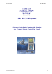
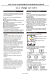
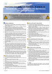
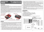
User manual
BR1
USER MANUAL
BR1, (BR2, BR3) systems
Wireless chain-rode Counter with
Windlass and Thruster remote
control for vessels
Function descriptions:
The system of wireless chain counter consists of:
- Wireless handheld unit BR1-Remote (BR2=BR1+stern thruster buttons)
- Base unit:
- BR1_Base (chain counter, windlass control)
- BR2_Base (chain counter, windlass, bow thruster, deck lights, pump)
- BR3_Base (chain counter, windlass, bow & stern thruster, deck lights, pump)
- Windlass sensor and magnet
- * WWS (Wireless Windlass Sensor) module for quick and easy installation (see
description on next page)
* Option available with BR2_Base and BR3_Base.
List of Material:
BR1 system: - BR1_Remote unit
- BR1_Base unit
BR2 system: - BR1_Remote unit
- BR2_Base unit
*OPTION - WWS (Wireless Windlass Sensor)
BR3 system: - BR3_Remote unit
- BR3_Base unit
- WWS (Wireless Windlass Sensor)
BR1 or BR2 or BR3 AND:
- Satin blue lanyard
- Magnet disc for windlass, diameter 8mm, heigh 5mm
- Reed contact sensor for windlass - universal
- 3xAAA Batteries (1,5V x 3pcs)
- Screews for fixing Base unit 2pcs
- CD Manuals English and in local language (download from www.boatremote.com)
ww.boat-remote.com
1
User manual
BR1
SAFETY NOTICES:
Product installation and Operation
- This product (BR1, BR2, BR3) must be installed and operated in accordance with the
instructions provided. Failure to do so could result in personal injury, death, damage to your vessel
and/or poor product performance.
Warning: Ensure safe operation
- Only skilled adult person with experience and knowledge for safe operation of anchor
windlass and boat thrusters may use this product!
- Improper use of equipment can be dangerous and can lead to life threatening situations
- ALWAYS CHECK BEFORE you operate the BR if it is safe and there is nobody in vicinity and
that use of windlass or thruster is not potentionaly dangerous to anybody arround.
- It is the user’s responsibility for safety use.
- Installation must be carried out by electrician.
DISCLAMER
- Producer is not responsible for damages or injuries caused by your use or inability to use the
product.
- The use of the BR1, BR2 or BR3 product is permited only on owners or captains own risk,
regardles of situation, cause or consequences.
- If you not agree or your jurisdictions do not allow the exclusion of incidental or consequential
damages, then you must return product within 8 days to sales point in original packaging and
unused to get money back.
Water ingress disclamer
Although the waterproof rating capacity of BR1, BR2 hand held unit exceeds that called for by the
IP67 standard and of BR1_Base IP65 standard, water intrusion and subsequent equipment failure
may occur if any equipment is subjected to running water, high pressure washing or submersing in
water. Producer will not warrant equipment subjected to those exposures.
Caution: Cleaning
When cleaning this product:
- Do NOT wipe the display screen with a dry cloth, or paper as this could scratch the screen
- Do NOT use abrasive, or acid or ammonia based products
- Do NOT use a pressure or jet wash
Caution: Direct sun light
To protect your product against the damaging effects of ultra violet light and to extend life time
keep BR handheld in shadow and dry place.
Caution: Power supply protection
When installing this product ensure the power source is adequately protected by means of a
suitably-rated fuse or automatic circuit breaker.
Product disposal
Dispose of this product in accordance with the WEEE Directive. The Waste Electrical and
Electronic Equipment (WEEE) Directive requires the recycling of waste electrical and electronic
equipment. Whilst the WEEE Directive does not apply to some BR products, we support its policy
and ask you to be aware of how to dispose of this product.
ww.boat-remote.com
2
User manual
BR1
Features of BR1_Handheld remote unit
ON/OFF
- To power ON hold. (Short double beeps)
- To power OFF press momentarly. (Long single beep)
- After power up on LCD caution message appear. BEFORE YOU CONFIRM CHECK if you
can operate BR safely! Confirm safety caution message by presing OK to proceede.
- If you suspect that anything is not operating normal, power OFF unit by pressing momentary
OFF button and check for malfunctions.
- To save battery BR1_Remote will switch off automatically after 10 minutes.
IMPORTANT SAFETY CAUTION:
For EMERGENCY STOP during operation, press ON/OFF momentarly and all output
rellays in Base unit will be disengaded immediatelly.
MENU,
- Press to enter menu.
- Hold 3sec for quick counter reset 00,0)
LIFT the ANCHOR (UP)
Windlass will lifting anchor as long as you keep pressing »UP«. Chain counter will
decrement chain – rode lenght.
IMPORTANT:
- When »UP LIMIT« is reached, windlass will stop even if you keep pressing »UP«.
To continue release »UP« and carefully lift remaining distance to dock the anchor.
By default this limit is set to 1m before anchor park.
- Limit can be set in Menu > Setings > Up Limit.
ww.boat-remote.com
3
User manual
BR1
LOWER the ANCHOR (DOWN)
Windlass will lower the anchor as long as you keep pressing »DOWN«. Chain counter
will increment chain-rode lenght.
IMPORTANT:
- When »DOWN LIMIT« is reached, windlass will stop even if you keep pressing
»DOWN«. To continue release »DOWN« and carefully lower remaining lenght of
chain - rode. By default this limit is set to 30m.
- Limit can be set in Menu > Setings > Down Limit.
BOW THRUSTER, left <> right (BR2_Base and BR3_Base)
Press momentarly for lateral movement of vessel.
IMPORTANT:
- To gain controll of bow thruster by BR you must enable Bow Thruster on
original controll panel first!
- For safety operation of Bow Thruster see producers manuals
QUICK FUNCTIONS
Press »OK« to enter quick function selection. See LCD for functions. Select quick
function by pressing a corresponding button (up,down, left, right). Pres »OK« for EXIT
without selection or wait until counter in lower right corner on LCD countdown to 0.
AUTO UP/DOWN
Select quick functions by pressing »OK« and press »UP« for
automatic lifting of anchor or select »DOWN« for automatic
lowering the anchor. Windlass will operate without holding the
button! AUTO function is active when simbol on right is
present on LCD.
IMPORTANT:
- Press any button to cancel AUTO UP/DOWN function and stop windlass!
- Keep remote unit in hand with thumb ready to momentarly press any button.
- AUTO function will stop when »UP LIMIT« or »DOWN LIMIT« is reached.
LIGHT ON/OFF (BR2_Base and BR3_Base)
Select quick functions by pressing »OK« and press BULB SIMBOL.
Highlighted symbol means »light ON«. Repeat to switch light OFF.
During normal operation in botom row symbol of bulb is indicating »light
ON«. Available with BR2_Base and BR3_Base
WATER PUMP (BR2_Base and BR3_Base)
Select quick functions by pressing »OK« and press WATER TAP symbol.
Highlighted symbol means »pump ON«. Repeat to switch pump OFF.
During normal operation in botom row symbol of water tap is indicating
»pump ON«.
ww.boat-remote.com
4
User manual
BR1
SETUP – handheld unit
Press »M« (Menu) to enter menu mode.
In MENU mode use arrow keys (up, down, left and right) to select.
Use »OK« to select, confirm and save.
Use »M« or »back« symbol to cancel and exit without saving
Structure:
MENU:
- COUNTER RESET: (quick reset - press »M« for 3sec during normal operation)
--YES/NO (Yes – sets counter to 0)
- SETUP:
--- UP LIMIT (default set to 1,5m)
--- DOWN LIMIT (default set to 30m)
--- CALIBRATION:
---- NUMBER OF MAGNETS, (pulses per turn, default 1)
---- CHAIN PER TURN (default 330mm)
-- UNITS: (see arrow)
--- METRES (M)
--- FEET (F)
--- REVOLUTIONS (R)
- SELECT CHANNEL: Available channels 2-13
-- Select channel and confirm with »OK« or exit without saving with »M«.
IMPORTANT:
BASE has to be in close range.
If signal is not good channel selection is not possible.
It is possible to select channel only with remote unit logged to base.
- LOGIN. To enter new handheld remote unit to base you need to enable »ADD new
remote to base« in base FIRST! See SETUP-base.
While leds (on base) are blinking confirm »LOGIN« on handheld remote unit.
See report on LCD:
LOGGIN SUCESS - LCD you will see report. Press »M« for exit from Menu.
LOGIN FAILED – can be caused by comunnication interferences, bad batteries in
handheld, full or bad memory, damaged one or both of units
- LANGUAGE:
-- ENGLISH
-- GERMAN
-- SPANISH
-- SLOVENSKO
ww.boat-remote.com
5
User manual
BR1
Calibration of chain/rode counter
Sensor on windlass is detecting revolutions of windlass gibsy. Lengh of chain/rode
deployed(winched) per revolution has to be adjusted to achieve aqurate chain counter reading.
First you need to set up number of pulses per gipsy revolution.
Select, MENU > SETUP > CALIBRATION >:
- NUMBER OF MAGNETS, (pulses per turn, default set to 1)
Set number of pulses per one turn of windlass gipsy. One pulse per revolution is
standard for majority of windlasses on market.
- CHAIN PER TURN (default METRES-330mm, FEET-12,9inch )
Calculate value of »CHAIN PER TURN):
You need to calculate chain lenght per one gipsy turn and enter value in »CHAIN PER TURN«.
A. Mark gipsy with duct tape and count revolutions while lowering or lifting anchor with BR1
remote or original switches for controling anchor windlass.
You can count revolutions also with BR1
Select: MENU > SETUP > UNITS > REVOLUTIONS > Exit from menu.
B. Set chain on starting position and reset counter, hold »M« for 3sec. If chain is skipping gipsy
when anchor is lowering then count number of turns rather at lifting it.
C. Lower or lift ancchor chain/rode
D. Calculate value of »chain per turn«:
Example1: On chain lenght of 10m 31 revolution is counted.
Calculation: 10m/31rev = 10.000mm/31rev = 322,5mm > enter: 323mm
Example2: At lifting full 50m of chain 154 revolutions was counted.
Calculation: 50m/154rev = 50.000mm/154rev = 324,6mm > enter: 325mm
E. Enter calculated value in:
MENU > CALIBRATION > CHAIN PER TURN – enter value
F. Select desired units. For »metres« select:
MENU > SETUP > UNITS > METRES > Exit from menu.
IMPORTANT:
Chain should run smooth and without skipping. If not, counter can't be acurate and
automatic stop safety function will not stop every time on same chain lenght.
ww.boat-remote.com
6
User manual
BR1
BR1_BASE
BR1_BASE communicate bidirectionally with wireless
hand held unit. With buttons on hand held, relays on base
are controlled. Relays providing + signal to operate
standard windlass contactor. Sensor is counting windlass
revolutions and base is calculating chain-rode deployed and
transmiting result to handheld unit.
LD1 (UP) in LD2 (DOWN) Relay output indication
LD5-SENS red Magnet over sensor indication. Handy for
test during installation.
LD4-VF yellow Lights when handheld is operating,
(Flashing when error occurs on RF module)
LD3-PWR, green Lights when operating and slowly
flashing when base is in sleep mode.
PROG button for adding new remotes to base and for
deleting memory.
IMPORTANT:
ANTENNA is 165mm long wire and should never be shortened, cutted, extended or
anyhow modified. Antenna is directly influencing communication quality and safety of system.
Never tight antenna with plastic tie to other cables or parallel with metal. For high frequency it is
like being shortened to ground and range will be in that case substantially reduced.
Base – setup
1. ADD new handheld unit to base:
- Press PROG button on base shortly 3 times (3x …)
- LEDs will start to flash
- during LEDs flashing on base unit select »LOGIN IN BASE« on handheld unit
- See LCD for report
- LOGGIN SUCESS – LEDs stop blinking
2. DELETE MEMORY (all handhelds and setup):
- Press PROG button on base shortly 3 times (3x …)
- LEDs will start to flash
- Hold PROG for 5 seconds
- LEDs will go ON for 2 seconds. Memory is erased.
3. EXIT:
-press PROG button shortly to cancel function
-or wait 5 minutes for auto exit. Memory will remain unchanged
ww.boat-remote.com
7
User manual
BR1
INSTALLATION
correctly - glands from bottom
RECOMMENDED!!
WRONG
WRONG
BE CAREFULL – HIGH HUMIDITY
IMPORTANT:
- Both ways are correct for BR1_Base, but you need to be more accurate and pedant when
installing BR1_Base unit in chain locker to prevent corrosion of connections.
- If BR1 is recommend to be installed in additional watter protected enclosure IP65.
- BR2_Base and BR3_Base should never and under no circumstancess be installed in chain
locker unless it is installed in additional watter protected enclosure IP65. It is also
recommended for BR1 especially if mounting area is not vertical, flat or if BR1 is oftenly
exposed to running water.
ww.boat-remote.com
8
User manual
BR1
BR1_Base installed in front cabin
It is recommended to install BR1_Base unit inside vessel in dry place.
Make connections (piggyback) at windlass contactor where you will find all necessary wires.
IMPORTANT
Before installation disconnect power!
Check with instrument if windlass power is really disconected.
BR1_Base enclosure must be oriented vertically with glands down.
For metal and carbon vessels check range before fix installation.
ww.boat-remote.com
9
User manual
BR1
BR1_Base installed in chain locker
This is the most simple and fast way to install BR1_Base on vessel, but you need to make hi
quality connections for long years trouble free and safe operation.
Complete all three connections marked with exclamation mark on shematic in separate IP65 box
and use connection method which will prevent water to penetrate and corode wires and contacts.
IMPORTANT
Only two cables may enter BR1_Base! (cable for power and control, cable for sensor)
Before installation disconnect power!
Check with instrument if windlass power is really disconected.
BR1_Base enclosure must be oriented vertically with glands down.
For metal and carbon vessels check range before fix installation.
Do not use water preasure cleaning on or near BR1_Base!
BR1_Base enclosure is made by IP65 standard (running water and dust resistant). Before fixing
the cover check gasket to be on place. With time gasket looses elasticity and water protection is
lower. It is recommended to prime gasket with vaseline before closing cover. Always gently
screew cover screews till end.
Ground wire connect directly to windlass motor only as last solution if you have no other
dedicated ground connection available in chain locker. The most issues are recorded exactly
because of bad contacts on windlass ground wires or because they are undersized.
ww.boat-remote.com
10
User manual
BR1
ALWAYS make connections in protection box (IP65).
Make quality connections and protect them.
1 - terminal
2 - soldered
3 - shrink tube with glue
4 - wire
5 - greased
Windlass sensor instalation
If windlass is not yet equipped with sensor then use universal added in kit.
Magnet
- Drill 8mm(diameter) hole, 7mm deep for magnet in anchor gypsy.
It is normally made
from brass and it is eassy to drill. Mark
position with smaller drill first.
- Glue magnet with epoxy. If you not cover (protect) magnet with
enough epoxy it will rust and decay in short time.
N/S pole orientation is not influencing sensing distance.
Orientation of sensor respect to magnet and rotation:
Sensor
For sensor installation universal holder is not available. You need to use your own technical skills
to fix sensor in magnet field range. For ideas and examples of installation check picture gallery on
www.boat-remote.com .
Orientation of sensor must corespond to above instructions. For installation you can use standard
nylon 7mm cable gland. Fix nylon gland, insert sensor, trim distance and tighten the cap to fix
sensor.
ww.boat-remote.com
11
User manual
BR1
Technical data
Product: BR1 system
Wireless handheld remote: typ, BR1_Remote
Display: LCD transflective, direct sunlight viewable
Resolution: 128 x 64 pixels
Back light: yes (smart)
Keypad: foil with perforated buttons, watertight
Power: batery AAA x 3pcs (for one year operation)
Power consumption: 41mA with back light, StBy:33mA, (OFF-9uA)
Protection: IP67 Handheld remote unit is moisture ressistant, operation with wet hands,
rain, water splash (not under presure). Unit is made to be water resistant, but we do not
guaranty to be watertight when submerged in water. Please carefully follow battery
replacement instructions for maximal water resistance.
Dimensions: 120mm x 70mm x 30mm (long, wide, deep)
Weight:
Base : typ, BR1_BaseV20
Power supply: 12-24V, min 9V
Power consumption: @ relay on: 87mA, StBy: 40mA, sleep: 13mA
Outputs: 2 (UP, DWN)
Output type: relay 20A, current limited with fuse 5A
Sensor input: reed voltageless – clasic or hall
Dimensions: 120mm (140mm with glands) x 80mm x 42mm (long, wide, deep)
Teža:
Communication: bidirectional
Range: min 20m @wood or plastic hull, min10m @ metall hull
Number of channels: 13 channels (2-13 available for custom selection)
Frequency: 434.040-434.790MHz
RF power (e.r.p): 10mW
Bandwidth: 25kHz
Standard: ETSI EN 300 220-3, clas 1e2
Comm. speed: 8kbps
FEC: 8 bit
coding: 32 bit
Produced by:
Harpoon elektronika d.o.o.
Hrastovec 14
1236 Trzin, Slovenia EU
ww.boat-remote.com
12