1
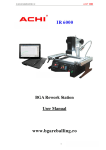
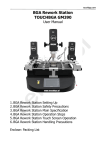
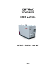
touchbga.com TOUCHBGA BGA Rework Station GM330 IR+HR User Manual touchbga.com Table of contents 1. GM330 BGA rework station features 1.1.Safety Instrouctions 1.1.1.Electric Safety 1.1.1.Operation Safety 1.1.3.Environmental requirements of operation and conservation 2.The operation and conservation condition of products 2.1.The parameters of GM330 BGA Rework Station 2.2.Hardware description and Self-help install 2.3.Temperature-controlled meter Operation instructions 2.4.BGA Rework operation steps 2.5.Prompt touchbga.com 1. GM330 BGA rework stations features GM330 BGA Rework Station is designed to meet the ever-changing demands of today’s fast BGA Rework manufacturing environments. This model have following characteristics: 1. Rework station for laptop motherboards, desktop computer motherboards, server boards, industrial computer boards, all kinds of game boards, communications equipment motherboards, LCD TVs and other large circuit board BGA rework. 2. Innovative designs. An effective solution to general of infrared rework station vulnerable to the impact of air flow. Will lead an inaccurate of temperature control. Maximum temperature up to 400C. Can easily deal with lead-free soldering rework. 3. Can set up 8 rising temperature segments and 8 constant temperature segments to control. It can save 10 groups of temperature curves at one time. 4. Can be connected to a computer to be controlled more conveniently with a built-in PC RS232 port and proprietary software attached to it. Programmable. 5. Can easily rework the variety of CPU's seat, all kinds of shielding enclosures, replacement of various components slot Can easily deal with lead-free soldering rework. 6. Sensitive temperature measurement sensor to obtain an accurate and instantaneous temperature reading and monitoring. 7. BGA rework station the technology of closed-loop temperature control ensures accurate temperature process and even heat distribution. 8. Machine overall system integration design. Rework station more integrated workbench area occupied by smaller. Didn't mixed and disorderly of cables. 9. Linear guide type Bracket for BGA Reworks can be locking adjusted by rotating the handle. Can be very easily fixed PCB board, effectively prevent the deformation of PCB board. 10. Detachable K type thermocouple. 11. Taiwan FOTEK SSR’s inside. Popular programmers inside. 1.1.Safety Instrouctions 1.1.1.Electric Safety 1. Make sure the supply power voltage accord with the standards 220V-250V/50hz alternating current before installing. 2. To avoid possible electric shock caused serious damage, please disconnect the power cord from the outlet temporary before moving machines. 3. If the machine damages, please contact us for maintenance. If the damage caused by the users when they dismantle or repair independently, they should take on the loss by themselves. touchbga.com 1.1.2.Operation Safety 1. Please carefully read the relevant information provided by the manual before starting using this product. 2. Make sure the power cord has been properly connected properly before using the products. 3. Installed the equipment in stable work platform to use, where the air mobility should be small as possible. Avoid it closing to air conditioners, fans and the other outlet. 4. In case of electrical short-circuit, avoid the products contacting with water. 5. Forbid using this equipment in flammable and explosive substances. 6. The operators’ hands or other parts of the body should maintain a safe distance from the heater. Forbid touching the heater to avoid scalding. 7. If you have any technical questions or suggestions in the course of using this product,please contact with our technology department. We will try our best to solve. 8. If there are metal object or liquid falling into to rework station while working, immediately break the power, pulled out power cable, after machine cooling, thoroughly cleared to fell thing, dirty mark again; If still stays dirty mark, may send out strange smell while re- switching on to work; 9. While BGA rework station to unusually heat or emit smoke, immediately break the power, and notify that the technique attendant maintains. Still continue to use while above-mentioned circumstance happening, may result in a fire or arouse electric shock; 1.1.3.Environmental requirements of operation and conservation 1. Operation environment of products - Operation temperature: 15 – 45C - Operation humidity: 5% to 95%, non-condensing - Products should be kept in the air mobility of a smaller environment under the welding operation. 2. Conservation environment of products - Storage temperature: -20 – 70C - Storage humidity: 5% to 95%, non-condensing Notice: BGA rework station use as usual production in will produce little strange smell, for make sure the comfort operation environment of health and safety, please keep indoor outside air to circulate. touchbga.com 2.1.The parameters of GM330 BGA Rework Station Heating kind IR/HR Dimension 445(WIDTH)x550(HIGH)x440mm(DEPTH) Weight 19kg Electrical Parameters Power 220-250V AC Upper Heating IR/HR Size of Upper heating IR - 80x80mm Consumption of upper heating IR-450W / HR-1000W / CHX-300W Size of Bottom heating area 300x245mm Consumption of Bottom heating 4x600W General power IR+IR-2250W/IR+HR-3400W Temperature Control Control mode of Upper Independent temperature control, high-precision closedloop control, precision ± 0.5%, Alarm Control mode of Bottom Independent temperature control, high-precision closedloop control, precision ± 0.5%, NO Alarm Rework Function BGA Suit for welding, remove or repair packaged devices such as BGA,PBGA,CSP,multi-layer substrates EMI metallic shield product and solder/lead free Rework welding Size of applicable chips <=80x80mm Size of applicable PCB <=320x300mm touchbga.com 2.2. Hardware description GM330 BGA Rework Station is composed of upper part of Heating Components / Bottom Preheat Module / Bracket / Temperature Control Parts! Temperature control table is control the upper and lower heating, can simultaneously heated or first preheat, then the upper part of heating. 3 4 5 16 6 10 13 1. PCB Table 2. Highly Sensitive K-temperature sensor 3. Upper Heater IR/HR 4. X-Y-Z Lifting Regulators 5. LED Auxiliary Lighting 6. Bottom Heater (Pre-Heater) 7. Lighting Switch 8. Upper + cross fan Switch 9. Vacuum suction pen Switch 10. Vacuum suction pen 11. Start Switch 12. Stop Switch 13. Upper Programmable Temperature Controller 14. Bottom Temperature Controller 15. Power Switch 16. Irregular PCB holders 14 2 9 8 7 11 12 15 touchbga.com 17 17. RS232 port for PC comunnication 18. Main power switch 18 touchbga.com 2.3. Temperature-controlled meter Operation instructions TOP Programmer/Controller General Description The programmable controller contains an in-built setpoint generator in addition to the controller function. This setpoint generator can produce a temperature/time profile with 10*16 segments (0 9 10 Sets of Curves). When the program is running, the current setpoint from the setpoint generator is fed to the control algorithm. The current setpoint is continuously shown on the lower display. The sixteen segments are defined in the order: Ramp 1, Dwell period 1, Ramp 2, Dwell period 2..., and are executed in succession. touchbga.com Program Parameters Setting touchbga.com Program Parameter List touchbga.com BOTTOM Programmer/Controller General Description Hold down the SET button of bottom heater temperature control instrumentation for 5 seconds, the display will blinking and using up/down buttons temperature of bottom heater. Using left arrow you can change one of four number positions. The factory temperature is set is 180°C. Generally the user needn’t to change the data. touchbga.com 2.4. Rework Operation Steps 1.Be all set 1.1.Fixed motherboard 1.2.Shift sensor close to BGA chip. 1.3.Adjust the height of heating head with adjustment knob Prompt: BGA chip in the middle of heating head, heating head distance from BGA: - IR - chip >= 2cm - HR - chip 3-5cm touchbga.com 2.Start heating 2.1.Select the appropriate temperature program segment for top heater (SET/PROG on ALTEC PC410), set temperature for bottom heater (SET on REX C100) and then press the START switch. In the operation can press the STOP switch, stop operating. 2.2.After the program runs, automatic alarm 8sec. and automatically cut off the heating power, this time you can check the following solder ball is completely liquefied, BGA chips should be subject to settlement, floating state . 3.Rework completed 3.1. Moving Heating head and Sensor, open the Upper fan Switch. 3.2.Remove motherboard. Clear insulating tape. 3.3.BGA Rework Station Cooled, Then close Total Power. Warning 1.If BGA Rework Station NO Cooling, Do not close the Total Power ! 2.When the temperature is not cooled, do not touch heating module! touchbga.com Prompt 1. Keep the equipment at a steady working environment where the air mobility should be as small as possible. Avoid it closing to air conditioners, fans and the other outlet. 2. IR 6000 Rework Station sensor is directly contacted with motherboards, So the display temperature is Actual temperature. 3. In order to avoid damages to the motherboard capacitor, please use insulation tape. After Maintenance is completed, Remove the insulation tape to prevent from short-circuit. 4. After removal of BGA chip PCB bonding pad needs to be cleaned up, Avoid cold solder joint. See BGA chip tin completely liquefied, then move the BGA chip to avoid Bonding Pad Damage. 5. During the reflow of the new ball in a typical tin/lead (Sn63/Pb37) com position, there are “self alignment” properties that are quite forgiving. According to IPC Spec, landing on 75% of the pad is acceptable for BGA rework. 6. To improve success rate of Rework, PCB and chips need drying and processing in principle PCB board or chip moist heat process will occur in the burst phenomenon, the Rework process may hear the blasting sound of a minor. According to actual situation Please self-control. 7. PCB board heating time is too long or repeated several times the surface heating will lead to discoloration. 8. Users from modifying temperature parameters. Please use scrap PCB tested heating whole time about 10 seconds before the end of solder balls should be fully liquefied f the liquefaction advanced or delayed, should be regulating up/down the temperature setting. To prevent heat damage to your chips or lowtemperature sealing off. 9. Common setting of temperature Reflow temp Sn63Pb37 : 185 - 190C, Reflow time: 10sec. Reflow temp Sn96,5Ag3Cu0,5: 220 - 225C, Reflow time: 15sec. touchbga.com 10. The meaning of“ Hb”: “Hb” means the max heating temperature of the upper heating. We set the max temperature at 230°C according to the max temperatrue of lead-free Reweork and other technical reasons. The data needn’t to be changed. 11.The meaning of “r1” “L1” “d1” “r2” “L2” “d2” “r3” “L3” “d3” …… Please pay attention to The following pictures and tables: touchbga.com 12.GM330 can be managed by dedidated software using RS232 cable. touchbga.com Rework temperature curve to set examples for IR head 1. LEAD Sn63Pb37 2. LEAD-FREE Sn96.5Ag3Cu0.5 3. XBOX/PS3 4. LEAD-FREE REFLOW Sn96.5Ag3Cu0.5 BOTTOM HEATER Slope/S Numerical Temperature Numerical C r1 r2 r3 r4 Slope/S value C 1 1 1 1 Numerical value C 165 185 215 225 Numerical Temperature time sec. Numerical value sec. d1 d2 d3 d4 Temperature time sec. 30 30 20 30 Numerical value sec. value C 1 1 1 1 1 Numerical C r1 r2 r3 r4 r5 Slope/S d1 d2 d3 d4 d5 Temperature time sec. 35 30 25 20 30 Numerical value sec. value C 1 1 1 1 1 Numerical C r1 r2 r3 r4 r5 Slope/S L1 L2 L3 L4 L5 Temperature value C 170 190 220 240 260 Numerical value C d1 d2 d3 d4 d5 Temperature time sec. 35 35 30 25 25 Numerical value sec. value C C r1 SLEEP L1 0 d1 200 r2 r3 r4 r5 1 1 1 1 L2 L3 L4 L5 170 190 225 255 d2 d3 d4 d5 35 35 30 30 L1 L2 L3 L4 Temperature L1 L2 L3 L4 L5 Temperature value C 175 190 225 245 250 Numerical TEMP=180C touchbga.com Rework temperature curve to set examples for HR head 1. LEAD Sn63Pb37 2. LEAD-FREE Sn96.5Ag3Cu0.5 3. XBOX/PS3 4. LEAD-FREE REFLOW Sn96.5Ag3Cu0.5 BOTTOM HEATER Slope/S Numerical Temperature Numerical C r1 r2 r3 r4 Slope/S value C 1 1 1 1 Numerical value C 165 185 210 225 Numerical Temperature time sec. Numerical value sec. d1 d2 d3 d4 Temperature time sec. 20 20 20 30 Numerical value sec. value C 1 1 1 1 1 Numerical C r1 r2 r3 r4 r5 Slope/S d1 d2 d3 d4 d5 Temperature time sec. 20 20 20 10 20 Numerical value sec. value C 1 1 1 1 1 Numerical C r1 r2 r3 r4 r5 Slope/S L1 L2 L3 L4 L5 Temperature value C 170 190 220 240 265 Numerical value C d1 d2 d3 d4 d5 Temperature time sec. 25 25 25 25 30 Numerical value sec. value C C r1 SLEEP L1 0 d1 200 r2 r3 r4 r5 r6 1 1 1 1 1 L2 L3 L4 L5 L6 170 195 225 245 260 d2 d3 d4 d5 d6 20 20 20 15 25 L1 L2 L3 L4 Temperature L1 L2 L3 L4 L5 Temperature value C 170 190 220 230 250 Numerical TEMP=180C