1
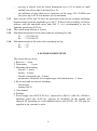
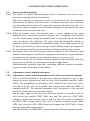
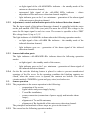
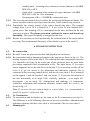
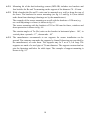
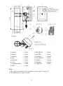
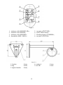
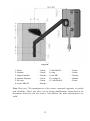
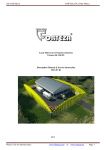
Dual-Technology Linear Intrusion Sensor
«MIR-B100»
«MIR-B50»
User Manual
Document Part Number 4372-43071246-073
2010
CONTENTS
1.
2.
3.
4.
5.
5.1.
5.2.
5.3.
6.
6.1.
6.2.
6.3.
7.
8.
8.1.
8.2.
8.3.
9.
9.1.
9.2.
9.3.
9.4.
9.5.
10.
10.1.
10.2.
11.
12.
13.
Introduction ...................................................................................................
Purpose ..........................................................................................................
Specifications ................................................................................................
Sensor components........................................................................................
Sensor structure & operation .........................................................................
Sensor operation principle.............................................................................
Adjustment, control and indication parts ......................................................
Sensor operation ............................................................................................
Sensor construction .......................................................................................
Rx construction .............................................................................................
Tx construction ..............................................................................................
Mounting kit ..................................................................................................
Safety measures .............................................................................................
Mounting procedure ......................................................................................
Requirements for the protected sector and Rx and Tx arrangement .............
Sensor mounting ............................................................................................
Sensor connection .........................................................................................
Preparation of the sensor for the operation & adjustment ............................
Sensor preparation for its operation ..............................................................
Tx and Rx adjustment ...................................................................................
Possibility of sensor installation on sites, which don’t meet the requirements
of the items 3.5, 8.1.1 ....................................................................................
Thresholds alignment of the Rx microwave detection channel ....................
Check of dual-technology sensor operation……………………………….
Check of technical state ................................................................................
Check of sensor operation .............................................................................
Maintenance ..................................................................................................
Troubleshooting Guide..................................................................................
Storage ...........................................................................................................
Transportation ...............................................................................................
Certificate ......................................................................................................
2
3
3
3
6
7
7
7
8
9
9
9
9
14
14
14
15
16
20
20
20
21
21
22
22
22
22
23
24
24
25
1. INTRODUCTION
1.1.
The user manual contains information about the operation of the dual-technology
intrusion sensor «MIR-B100», «MIR-B50» (below the sensor). There is the
information required for the correct operation (use, transportation, storage and
maintenance) of the sensor.
The following abbreviations are used in this document:
Tx - transmitter
Rx - receiver
MK - mounting kit
MW – microwave detection channel
IR – active infrared detection channel
2. PURPOSE
2.1.
2.2.
2.3.
The sensor is intended to protect fences, perimeter sites, windows and inner
facilities.
The sensor combines two physical detection principles (IR and MW). It increases
the sensor interference immunity and allows to use the sensor in harsh interference
conditions.
The sensor is intended for continuous round-the-clock outdoor operation at an
ambient temperature from -40˚up to+65˚C and relative humidity up to 98% at the
temperature +35 С.
3. SPECIFICATIONS
3.1.
3.2.
3.3.
The recommended length of a protected sector: – 10…100 m;
Microwave and infrared detection channels have different configurations of the
detection zone. The alarm is generated when both detection channels (microwave
and infrared) are activated. As a result the final configuration of the detection zone
coincides with the configuration of the infrared channel detection zone.
The detection zone configurations (microwave and infrared) and their dimensions
are given in fig.3.1 and table 3.1.
The detection zone is a volumetric part of the protected sector, within the scope of
which any movement of an intruder generates an alarm.
3
Fig. 3.1
L – length of a sector;
B – diameter of the MW detection zone;
D – diameter of the IR detection zone.
In fig.3.1 and table 3.1 the diameter (B) of the microwave detection zone and the
diameter (D) of the infrared detection zone are given for the middle of the
protected sector. Moving towards the receiver or transmitter these dimensions
decrease gradually up to the geometry of the receiver and transmitter.
Table 3.1
3.4.
3.4.1.
3.4.2.
3.4.3.
Dimension,
maximum,
m
10
25
50
100
B
0,5
0,7
1,0
1,5
D
0,03
0,05
0,1
0,2
Length of a sector L, m
Main features of the infrared detection channel.
Number of IR-rays - 1;
Angle of the IR-ray divergence - 20;
Light immunity:
- to daylight and dc light sources – up to 20 000 lx;
- to ac light sources – up to 1000 lx;
3.4.4. Sensitivity (IR-ray overlap time) - 45 ms;
3.4.5. IR-ray interference immunity – up to 35 ms.
3.5.
The recommended distance from the axis of the detection zone up to fences,
building walls and other motionless objects at the sector length:
50…100 m
1,0 m minimum;
4
3.6.
3.7.
3.8.
3.9.
3.10.
3.11.
3.12.
25…50 m
0,5 m minimum;
10…25 m
0,35 m minimum.
The recommended distance from the axis of the detection zone can be less if the
requirements of the item 9.3. are fulfilled.
The sensor generates an alarm when:
an intruder crosses the detection zone at a speed from 0,1 up to 6 m/sec (the
minimum detection probability is 98 %);
remote control signal is transmitted to Tx;
The alarm is generated by breaking actuating relay contacts. The indicator
«ALARM MW+IR» goes on for 3 sec minimum. This signal is sent from Rx by
the yellow and pink wires marked «NC» (normally closed).
The sensor generates the fault signal at:
the absence of the Tx signal:
at the infrared detection channel – the indicator «ALARM IR» on the Rx
backboard goes on till the failure is eliminated;
at the microwave detection channel – the indicator «ALARM MW» on the Rx
backboard goes on till the failure is eliminated;
at the infrared and microwave detection channels – all Rx indicators go on
and actuating optoelectronic relay contacts are broken (the yellow and pink
wires marked «NC», «NC) till the failure is eliminated;
the absence of supply voltage or at its reduction lower than 15 V;
a failure of Rx or Tx.
The actuating relay characteristics are: maximum switching current is up to 0,1 A;
maximum voltage is up to 50 V; maximum resistance is up to 110 Ohm in the
closed condition (together with lightning guard elements).
The sensor generates the alarm at the opening of the Rx cover, under which there
are adjusters. The contacts of the blocking button are open at the cover opening.
This alarm is transmitted to Rx by the green and grey wires marked «TAMPER»,
«TAMPER». Operating characteristics of the blocking contacts: current is up to 0,2
A; voltage is up to 80 V.
The sensor power supply: from 15 up to 30 VDC with the maximum pulsation of
0,02 V. The maximum current consumption is 35 mA at 24 VDC.
The sensor operation can be controlled remotely by biasing the dc voltage of
5…30 V at the wire marked «RC» on the Tx unit. The duration of this test is 2…4
sec.
The sensor doesn’t generate the false alarm at:
rain, snow, thick fog;
solar radiation;
wind speed up to 30 m/sec.;
5
-
3.13.
3.14.
3.15.
3.16.
moving of objects with the linear dimensions up to 0,2 m (birds or small
animals) not closer than 5 m from Rx or Tx;
the influence of ultra short waves emissions of the range 150-175 MHz and
the power up to 40 W at a distance of 6 m minimum.
Input circuits of Rx and Tx have the protection from electric pickups (including
thunderstorms) with the amplitude up to 900 V. If there is the possibility of electric
pickups with the amplitude more than 900 V, it is recommended to use the
lightning guard unit «LGU-4».
The sensor mean lifetime is 8 years.
Maximum dimensions of the units without a mounting kit, mm:
Tx - 211x138x105;
Rx - 211x138x105.
Maximum weight of the units with a mounting kit, kg:
Tx - 1,5;
Rx - 1,5.
4. SENSOR COMPONENTS
The sensor delivery kit is:
1. Receiver – 1 item.
2. Transmitter - 1 item.
3. Mounting kit including:
- bracket – 2 items;
- buckle – 4 items;
- flexible corrugated pipe– 2 items;
- nonhermetic connector of corrugated pipe with junction box – 2 items.
4. Kit of tools and accessories including:
- alarm cable;
- spanner S8x10
5. User manual.
6. Package.
7. Power supply unit «PSU-U-24-0,5», junction box «JB-15» («JB-30», «JB-84»),
lightning guard unit «LGU-4», supports for mounting on the ground and
supports for mounting on a wall indented from a wall at 500, 350, 120 mm are
supplied at the customer’s order.
6
5. SENSOR STRUCTURE & OPERATION
5.1.
Sensor operation principle
5.1.1. The sensor is a bistatic dual-technology device. Transmitter and receiver have
microwave and infrared detection channels.
The sensor principle of operation is based on generation of an electromagnetic
field between Tx and Rx. This field forms a volumetric detection zone in the form
of a long ellipsoid of rotation. The sensor also generates an infrared ray (fig. 3.1).
The sensor registers changes of the field and overlapping of the infrared ray when
an intruder crosses the protected zone.
5.1.2. When an intruder crosses the detection zone, it causes changes of the signal
amplitude in Rx (microwave detection channel) and overlapping of the infrared
ray. The signal passes through the amplifier and is compared with the thresholds
value according to the algorithm. The signal from the infrared Rx module is
analysed (time of overlapping and modulation depth). If the signal change on the
Rx input is provoked by a person passage and the infrared beam is overlapped for
the required time, then Rx generates an alarm breaking actuating relay contacts.
5.1.3. Interference factors for the microwave detection channel are the following: small
animals, electromagnetic interference, swinging of tree branches or gates, transport
movement near the detection zone, motionless objects (e.g. snow cover).
Interference factors for the infrared detection channel are the following: thick fog,
heavy snow or leaf fall, powerful natural or artificial light sources.
Multi-thresholds operation algorithm, combining different detection principles,
permits to reduce the number of false alarms.
5.2.
Adjustment, control and indication parts
5.2.1. Adjustment, control and indication parts of the microwave detection channel
Values of the Rx thresholds of the microwave detection channel are set by a user
during the sensor operation and with the help of the threshold controller «MINMAX». The thresholding is performed by slow rotation of the resistor axis with a
screwdriver. In this case the threshold value changes from minimum (MIN) to
maximum (MAX). The minimal thresholds value corresponds to the maximal
sensitivity of the microwave detection channel.
The Rx input signal of the microwave detection channel is controlled with the
tester on the jack marked «TEST MW» (test jack).The more the «TEST MW»
voltage is, the more the Rx input signal is and vice versa. The sensor is operable at
the «TEST MW» voltage from 0,1 up to 4,8 V. Connect a voltmeter to the «TEST
MW» jack, press the «AGC MW» button and compare the «TEST MW» voltage
with the permissible voltage values.
The light indicator «ALARM MW» informs about the following operation modes:
7
no light signal of the «ALARM MW» indicator – the standby mode of the
microwave detection channel;
interrupted light signal of the «ALARM MW» indicator – «fast»
adjustment of the microwave detection channel amplifier;
light indicator goes on for 3 sec. minimum – generation of the alarm signal
of the microwave detection channel.
5.2.2. Adjustment, control and indication parts of the infrared detection channel.
-
The Rx input signal of the infrared detection channel is controlled with the tester
on the jack marked «TEST IR» (test jack).The more the «TEST IR» voltage is, the
more the Rx input signal is and vice versa. The sensor is operable at the «TEST
IR» voltage from 1,0 up to 3,5 V.
The light indicator «ALARM IR» informs about the following operation modes:
-
no light signal of the «ALARM IR» indicator – the standby mode of the
infrared detection channel;
-
light indicator goes on – generation of the alarm signal of the infrared
detection channel.
5.2.3. Sensors indication parts
The light indicator «ALARM MW+IR» informs about the following operation
modes:
-
no light signal – the standby mode of the sensor;
light indicator goes on for 3 sec. minimum – generation of alarm signal of
the infrared detection channel.
5.2.4. On the Rx unit the blocking button is placed in order to prevent unauthorized
openings of the Rx cover. In the operating condition the blocking contacts are
closed, when the sensor cover is opened, the contacts are broken. The alarm
circuits marked «TAMPER» (green and grey wires) are broken too.
5.3.
Sensor operation
5.3.1. The preparation to the sensor operation is the following:
- preparation of the sector;
- signal cables and power supply laying;
- Tx and Rx installation;
- sensor connection (connection of power supply and intruder alarm
loops);
- alignment of Tx and Rx antennas;
- alignment of Rx thresholds of the microwave detection channel.
The principles and methods of these steps are given in the items 8-9.
5.3.2. The sensor has the following operation modes:
-
8
standby mode – actuating relay contacts are closed, indicator «ALARM
MW+IR» is OFF;
- alarm mode – actuating relay contacts are open, indicator «ALARM
MW+IR» is ON for 3 sec. minimum;
- blocking state of Rx – «TAMPER» contacts are open.
5.3.3. The receiving and control device realizes the receipt and indication of alarms. The
sensor operates with the receiving-control devices, which control relay contacts.
5.3.4. Periodically the remote control of the sensor should take place. The constant
voltage from 5 up to 30 V is biased for 2…4 sec on the Tx wire marked «RC»
(green wire). The beaming of Tx is interrupted for the time and then the Rx unit
generates an alarm. The alarm generation confirms the sensor and alarm loop
operability. The control frequency is assigned by the user.
5.3.5. Besides it is necessary to check periodically the technical state of the sensor and its
servicing. The recommended frequency of the checks is given in the item 10.
-
6. SENSOR CONSTRUCTION
6.1.
Rx construction
6.1.1. Rx and Tx units are placed in the dust- and splash-proof enclosures.
6.1.2. Rx construction and its fastening elements to the support are shown in fig. 6.1. The
bearing structure of Rx is the base 4. The infrared and radio transparent enclosure
5 is fastened to the base. In the lower part of the enclosure there are three holes
preventing condensed fluid accumulation in Rx. The sight leaves 15 for easier
sensor alignment are on the side faces of the base 4. It is necessary to take off the
cover 6 to get the access to the adjustment and indication elements. Rx is
connected to the receiving-control device with the six-wire cable 8. Rx is mounted
on the support 1 with the bracket 2 and two bucles 13. It provides the rotation of
the unit horizontally at an angle 360 ; vertically: upwards - at an angle 45 ,
downwards – at an angle 15 . Arrangement and markings of components,
controllers, adjustment and indication elements, located under the cover 6, are
shown in fig. 6.2.
Note. To increase the unit rotation angle in vertical plane, it is recommended to
install the bracket 2 of the turn 180 .
6.2.
Tx Construction
6.2.1. Tx construction and its bracket are the same as the Rx construction (see fig.6.1).
The difference is in the following: there are no cover 6, controllers, adjustment and
indication elements; the three-wire cable is used instead of the six-wire cable 8.
6.3.
Mounting kit
9
6.3.1. Mounting kit of the dual-technology sensor (MW+IR) includes two brackets and
four buckles for Rx and Tx mounting on the support of the diameter 70…90 mm.
6.3.2. With a bracket the Rx and Tx units can be mounted on a wall or along the top of
the fence. The brackets for sensor mounting (see fig. 6.3 and fig. 6.4) one should
make them from drawings (drawings are by the manufacturer).
The example of the sensor mounting on a wall with the brackets of 120 mm (e.g.
on a wall adjoining to a fence) is shown in fig. 6.3.
The sensor mounting with the brackets of 350 or 500 mm for fence, windows and
doors protection is shown in fig. 6.4.
The rotation angles of Tx (Rx) units on the bracket in horizontal plane - 180˚, in
vertical plane: upwards - 17˚, downwards – 45о.
6.3.3. The manufacturer recommends to use supports for sensor installation on the
ground. The customer can make the supports by himself (drawings are provided by
the manufacturer) of order them. The supports may be 2 m or 2,5 m long. The
supports are made of a steel pipe of 76 mm diameter. The support construction has
pins for fastening and holes for cable input. The example of support mounting is
shown in fig. 8.3.
10
Fig. 6.1.
1-support
2-bracket
3-bushing
4-base
5-enclosure
6-cover
7-corrugated tube
8-cable
- 1 item;
- 1 item;
- 1 item;
- 1 item;
- 1 item;
- 1 item;
- 1 item;
- 1 item;
9-bolt M6x35
10-nut M6
11-washer 6
12-bolt M6x35
13-buckle
14-bushing
15-sight leaf
- 1 item;
- 1 item;
- 2 items;
- 1 item;
- 2 items;
- 2 items;
- 2 items.
Note:
1. The support mounting on the ground is given in fig.8.3 (item 8.2).
2. The dimensions are given in mm.
11
Fig.6.2
1 – indicator «ALARM MW+IR»;
2 – indicator «ALARM IR»;
3 – indicator «ALARM MW»;
4 – thresholds «MIN– MAX»;
1- bracket
2-ring
3- figured washer
-1item;
-1item;
-1item;
5 – test jack «TEST MW»
6 - «AGC MW» button;
7 – blocking button «TAMPER»;
8 – test jack «TEST IR».
Fig. 6.3
4- washer 6
5- nut М6
12
-1item;
-1item.
Fig. 6.4.
1- fence
2- bracket
3- figured washer
4- bracket fastener
5- Rx unit
6- screw М6х50
– 1item;
– 1item;
– 2items;
– 1item;
– 1item;
– 4items;
7- bolt М6х35
8- ring
9- nut М6
10- washer 6
11- bolt М6х14
– 1item;
– 1item;
– 2items;
– 4items;
– 1item.
Note. Dear user! The manufacturer of the sensor constantly upgrades its quality
and reliability. That’s why there can be design modifications unspecified in the
documents delivered with the sensors. Nevertheless, the main specifications are
valid.
13
7. SAFETY MEASURES
7.1.
7.2.
7.3.
7.4.
The current safety standards for the operation with electrical facilities with the
voltage up to1000 V should be observed during mounting, preventive maintenance
and repair of the sensor.
Cables should be laid, terminated and connected to the sockets only when the
supply voltage is OFF.
It is prohibited to mount and maintain the sensor at thunderstorms.
Installation and maintenance of the sensor must be performed only by people, who
underwent special safety trainings and became acquainted with safety measures.
8. MOUNTING PROCEDURE
8.1.
Requirements for the protected sector and the arrangement of Rx and Tx.
8.1.1. The protected sector should meet the following requirements to ensure the
microwave detection channel operability:
a) line of sight between Tx and Rx;
b) moving or motionless objects should not be situated in the detection zone of
the microwave detection channel (see fig. 3.1);
Note. The presence of motionless objects is permissible if the requirements of the
item 9.3 are fulfilled.
8.1.2. The protected sector should meet the following requirements to ensure the infrared
detection channel operability:
a) line of sight between Tx and Rx;
b) moving or motionless objects should not be situated in the detection zone of
the infrared detection channel (see fig. 3.1);
c) sensor units should not slant under the influence of wind, temperature
oscillations, vibrations and etc.
8.1.3. Advice how to reduce influence of interferences (false alarms possibility) on the
microwave detection channel:
a)
do not allow the presence of moving objects closer than 5 m from the
microwave channel detection zone (people and animals, tree branches, high
grass, wings of gates);
b)
do not allow transport movement closer than 1,5 m from the microwave
channel detection zone.
8.1.4. Advice how to reduce influence of interferences (false alarms possibility) on the
infrared detection channel:
a) remove snow and dust from sensor units;
14
b)
8.2.
exclude the influence of direct sunlight or powerful infrared lighting units on
Rx in the receiving direction ±20 (see fig. 6.1).
Sensor Mounting
8.2.1. Only Tx units or only Rx units must be installed at the joint of two adjoining
sectors. Tx and Rx units must not be installed next to each other on adjoining
sectors.
8.2.2. Ground installation type with supports is shown in fig. 8.3.
8.2.3. Installation on a wall (along the top of a fence) with a 350 mm bracket is shown in
fig. 6.4. Level difference of the fence edge relative to the microwave detection
channel axis must not exceed 0,35 m.
Attention! The right orientation of Tx and Rx on the bracket: drain ports
should be downwards! It is obligatory to install the corrugated pipe!
8.2.4. Usage of junction boxes «JB» and power supply units «PSU-24-0,5».
To connect the cable 8, protected with the corrugated pipe 7, with the JB (or PSU),
one should remove one of the threaded cable connections PG9 and place the
bushing 14 with the corrugated pipe 7 into the hole. It is recommended to use one
«PSU-U-24-0,5» for power supply of two contiguous sensors. It should be
remembered that there are five free terminal blocks in «PSU-U-24-0,5» («1» «5»).
ATTENTION! To reduce the level of electromagnetic interferences, it is
recommended to mount the power supply unit at a distance up to 300 m from
the place where the sensors are installed.
1 - support;
2 - plastic plug;
3 - hole for the cable input inside
the support;
4 - hole for the main cable and
sensor cable input;
5 - hole for the main cable input;
6 - concrete (gravel);
7 - dowels for prevention the
unauthorized dismounting of
the support;
8- ground
Note.
1. For A size the ground should
be laid after installation works.
2. Dimensions are given in
millimeters.
Fig. 8.3
15
8.3. Sensor connection
8.3.1. Connect the necessary power, signal and remote control circuits. Rx and Tx units
are connected with its own cables. The colour or marking of the cable conductors
indicate their purpose. The information about cable conductors marking, colour
and purpose is given in Table 8.1.
ATTENTION! It is categorically forbidden to «earth» the sensor circuits
directly. It is necessary to use the lightning guard unit «LGU-4»
Table 8.1
Marking
«+»
Rx
Colour
white
«-»
brown
«NC»
yellow
«NC»
pink
«TAMPER»
green
«TAMPER»
grey
Purpose
Supply voltage
Marking
«+»
Tx
Colour
white
«-»
brown
Actuating relay
«RC»
contacts
green
Purpose
Supply voltage
Remote control
+ 5…30 V
Blocking button
8.3.2. The type and rating of the terminator of the security system loop (resistor,
condenser and diode) are determined by the type of the receiving-control device,
with which the sensor is connected. Usually it is a resistor. The rated resistance of
this resistor should take into account the resistance of the lightning guard circuit
(this resistor - 100 Ohm) and the resistance of the security system loop (depends on
the chosen cable type and its length).
8.3.3. The contacts of the Rx blocking button («TAMPER») can be connected to the
receiving-control device with a separate loop. In this case the separate signal
indicates the opening of the Rx cover. The second variant is to connect the
blocking contacts in series with the actuating relay contacts. In this case an alarm
will be registered by one channel of the receiving-control device at the relay
actuation or at the opening of the Rx cover.
8.3.4. The scheme of the sensor connection using the junction box «JB-15» is shown in
Figure 8.4. The contacts of the blocking button are connected in series with the
actuating relay contacts. The sensor receives a signal from the remote control (RC)
when an additional button is installed at the post. It is possible to install one button
for several sensors. In this case the button pressing checks the operation of all
sensors.
The scheme of the sensor connection using the lightning guard unit «LGU-4» is
shown in Figure 8.5.
16
The scheme of the sensor connection to the supply unit «PSU-24-0,5» is shown in
Figure 8.6.
8.3.5. On the lengthy perimeters it is recommended to use junction boxes «JB-30» (with
30 circuits), «JB-48» (with 48 circuits) and «JB-84» (with 84 circuits) for cables
switching.
Terminator – terminator of the control-receiving device
Fig. 8.4
17
Terminator – terminator of the control-receiving device
Fig. 8.5
18
19
Terminator – terminator of the control-receiving device
Fig. 8.6
9. PREPARATION OF THE SENSOR FOR THE OPERATION AND
ADJUSTMENT
9.1.
Sensor preparation for its operation
9.1.1. Check the connection of supply circuits and output circuits of the sensor.
Switch ON the sensor power supply.
9.2.
Tx and Rx adjustment
9.2.1. Tx and Rx are adjusted according to the angle of elevation and the azimuth with
the aim to achieve the max «TEST IR» voltage.
9.2.2. Two persons should adjust the sensor. One of them is near Rx, the other – next to
Tx.
9.2.3. The alignment includes the following procedures:
connect the tester to the socket «TEST IR» using the alarm cable from the kit
in the mode of constant voltage measuring;
loosen the bolts12 and 9 (see fig.6.1) of Tx and Rx;
turn Tx and Rx in vertical and horizontal planes. Adjust them using the sight
leaves on the sidewalls of the antennas (approximate adjustment);
turn Tx and Rx in vertical and horizontal planes. Achieve the maximum
value of voltmeter (not less than 3,0 V) on the socket «TEST IR» (exact
adjustment);
tighten the bolts 12 and 9;
check the «TEST IR» voltage value after the alignment. It must be equal 3,03,5 V;
check the «TEST MW» voltage value after the alignment. It must be equal
1,2-4,5 V.
If the «TEST IR» and «TEST MW» voltages are beyond the limits, it is
necessary to repeat the alignment vertically and horizontally for more
accurate alignment;
Note: 1) The sensor is operable at the «TEST IR» voltage from 1,0 up to 3,5 V, at the
«TEST MW» voltage from 0,1 up to 4,8 V. Margin limits during alignment are
recommended with the aim to provide the capacity of signal level. It provides longterm and stable operability of the sensor;
2) On short sites (less than 20 m) the «TEST MW» voltage may be more than
the upper limit. In this case it is necessary to disalign Rx unit upwards at a small
angle so the «TEST MW» and «TEST IR» voltages are within the limits.
disconnect the tester.
20
9.3.
Possibility of sensor installation on sites, which don’t meet the requirements of
items 3.5, 8.1.1.
9.3.1. The influence of different objects (especially lengthy ones) situated in the
detection zone is in the following:
–
decrease of microwave input signal;
–
unequal sensitivity along the protected site of both microwave and infrared
detection channels;
–
distortion of the microwave channel detection zone.
9.3.2. Minimum input signal of the microwave detection channel.
If after alignment according to the item 9.2 the «TEST MW» voltage is less
than 1,2 V, it is necessary to do the following:
–
to reduce the sector length;
–
to change the position of Tx and Rx units relative to the wall or fence by 30 50 mm and repeat the alignment.
If it is impossible to get 1,2 V on the «TEST MW» socket, as an exception it is
admissible to use the sensor at the signal level not less than 0,9 V.
9.3.3. The alignment of the microwave detection channel thresholds and the check of the
infrared channel detection ability should be carried out very carefully doing at least
10 check passes along the whole sector length.
9.3.4. If the detection zone configuration is distorted, one should check if movements
outside the detection zones mentioned in the item 3.3.
9.3.5. It is necessary to carry out sensor operation testing and to decide about the
possibility of sensor usage according to its results.
9.4.
Thresholds alignment of Rx microwave detection channel
9.4.1. Set the controller «MIN-MAX» in the position MAX. Regulate the thresholds,
crossing the protected sector along its whole length (beginning with the middle of
the sector). It is necessary to go out of the detection zone at a distance of 1-2 m for
Rx calming (otherwise the results of the previous passage will influence on the
following one). When the sensor generates alarms, «ALARM MW» indicator goes
on for 3 sec. minimum. The following passage can be done after the switching off
the indicator «ALARM MW». If the signal is not generated during the passage, the
controller «MIN-MAX» is turned a little counterclockwise and the alignment is
continued.
21
Do some check passes in «problem» places of the detection zone: hollows, hills,
near tree trunks. Regulate the thresholds of the microwave detection channel if
necessary.
Note. If check passages are done at a medium speed, the threshold values allow to detect
an intruder moving at a speed from 0,3 up to 6 m/sec. To expand the speed range
up to 0,1…6 m/sec you should conduct additional alignment crossing the sector at
a speed of 0,1 m/sec.
Align the thresholds very attentively as «underrating» of the thresholds might
provoke a lot of false alarms; «overrating» of the thresholds might provoke
failures in the sensor operation.
9.5.
Check of dual-technology sensor operation
9.5.1. Fulfilling the item 9.4.1 one should control that the indicators «ALARM IR» and
«ALARM MW+IR» turn on when the sector is crossed.
Close the Rx cover when the alignment is finished.
It is recommended to test the sensor for 2-3 days after its alignment with the aim to
detect possible errors in mounting and alignment.
10. CHECK OF TECHNICAL STATE
10.1. Check of sensor operation
10.1.1. During the exploitation it is recommended to test the sensor operability
transmitting the remote control signal («RC»). The customer sets the frequency of
such testing.
10.2. Maintenance
10.2.1. The sensor maintenance should be conducted by people, who underwent special
safety trainings.
10.2.2. During the sensor exploitation it is necessary to conduct check and preventive
works.
10.2.3. Every month carry out visual examination of the sensor units and the protected
sector.
It is necessary to check:
the absence of dust, dirt, snow and ice from the side of Tx signal
transmission and Rx signal reception;
the absence of foreign objects in the protected sector.
10.2.4. Every quarter:
carry out all monthly works;
check the cables and cable connections.
22
10.2.5. During seasonal works one should control the grass height (in summer) and the
snow cover height (in winter) in the detection zone.
11. TROUBLESHOOTING GUIDE
List of possible troubles is given in Table 11.1.
Table 11.1
Trouble
Possible Cause
1.The receiving control device
constantly generates an 1. Communication line
alarm.
is broken.
2. False alarms.
2. The protective
device in the PSU is
blown.
3. The sensor
alignment is
disturbed.
4. Tx is out of order.
5. Rx is out of order.
1. Moving branches in
the detection zone.
2. High grass in the
detection zone.
3. Snow blanket is
above the norm and
reduces the input
signal.
4. Animals movement
in the detection
zone.
5. The Rx thresholds
are too low.
3. The sensor does not
generate alarms when
an intruder crosses the
detection zone.
1. Rx thresholds are
too high.
2. The alignment is
disturbed.
23
Repair
Check the cable
integrity and the
accuracy of its
connection. Restore
the communication
line.
Replace the protective
device.
Align Tx and Rx
antennas.
Replace Tx.
Replace Rx.
Inspect the protected
sector and remove
interference factors.
Check the accuracy of
the Rx thresholds
settings.
Check the accuracy of
the Rx thresholds
settings.
Align Tx and Rx
antennas.
12. STORAGE
12.1.
The sensors should be warehoused in the package at an ambient temperature from
+5 С up to +30 С and relative humidity 85% maximum.
During storage the influence of hostile environment should be prevented.
13. TRANSPORTATION
13.1.
Packaged sensors can be transported by any transport (if by air transport – in
pressurized modules) if they are transported in covered cars, holds or covered
bodies at a distance up to 10 000 km.
The boxes should be carefully stowed in order to prevent their shifting or fall in the
case of jolts.
24
Dual-Technology Intrusion Sensor
«MIR-B100», «MIR-B50»
Certificate
Document Part Number 4372-43071246-073
The purpose of the sensor and its specifications are given in the respective items of the
user manual 4372-43071246-073.
1. DELIVERY KIT
The delivery kit includes:
transmitter
receiver
mounting kit
kit of tools and accessories
user manual, certificate
1 item
1 item
1 kit
1 kit
1 item.
2. ACCEPTANCE CERTIFICATE
The sensor «MIR-B_____», № ________________meets performance specifications of
the Document Part Number 4372-073-43071246-2010 and it is considered as operable.
Date of issue _________201 .
Quality department
3. MANUFACTURER’S WARRANTIES
3.1.
3.2.
3.3.
3.4.
The manufacturer guarantees the conformity of the sensor specifications to the
requirements of the Document Part Number 4372-041-43071246-2009 if a user meets the
service conditions and operating rules specified by the User Manual 4372-43071246073.
Warranty period is 3 years since the date of sale by the manufacturer.
Warranty does not cover the sensors:
with broken guarantee seals;
with mechanical failures,
sensors which are out of order because of natural disasters (lightning, fires or
floods).
Mean lifetime - 8 years.
25
Manufacturer
JSC «Okhrannaya Technika»
Postal address
Russia, 442960, Zarechnyj,
Penza region, post office box 45.
Contacts
Tel. +7 8412 655316
Fax. +7 8412 655316
E-mail: [email protected]
The detailed information you can find at
www.FORTEZA-EU.com
26