1
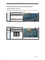
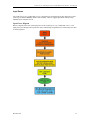
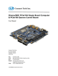
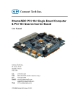
COM Express Type 6 PMC/XMC Carrier Users Guide Connect Tech Inc. 42 Arrow Road Guelph, Ontario N1K 1S6 Tel: Toll: Fax: Email: Web: 519-836-1291 800-426-8979 (North America only) 519-836-4878 [email protected] [email protected] www.connecttech.com CTIM-00115 Revision: 0.01, April 30, 2013 Connect Tech - COM Express Type-6 PMC/XMC Carrier Board - User Manual Table of Contents Customer Support Overview .......................................................................................................................... 4 Contact Information........................................................................................................................................ 4 Limited Lifetime Warranty ............................................................................................................................. 5 Copyright Notice ............................................................................................................................................ 5 Trademark Acknowledgment ......................................................................................................................... 5 Revision History ............................................................................................................................................. 5 Introduction .................................................................................................................................................... 6 ESD Warning ............................................................................................................................................................ 6 Product Features and Specifications ............................................................................................................... 7 Block Diagram ............................................................................................................................................... 8 Connector Locations ....................................................................................................................................... 9 Connector Summary ......................................................................................................................................10 Jumper Summary ...........................................................................................................................................11 Detailed Feature Pinouts and Functional Descriptions ..................................................................................12 COM Express Module Connector ........................................................................................................................... 12 CPU Fan Connector ................................................................................................................................................ 12 Input Power ............................................................................................................................................................. 13 Input Power Diagram .......................................................................................................................................13 Active Input Power Protection Details .............................................................................................................14 Input Power Connector Details ........................................................................................................................14 Video Outputs ......................................................................................................................................................... 15 HDMI and Display Port ...................................................................................................................................15 DVI ..................................................................................................................................................................16 LVDS Video ....................................................................................................................................................17 Description ....................................................................................................................................................17 LVDS Video Header .....................................................................................................................................17 LVDS Backlight Power Connector ...............................................................................................................18 LVDS Backlight Power Jumper ....................................................................................................................18 LVDS Panel LEDADJ Selection Jumper ......................................................................................................19 VGA .................................................................................................................................................................19 VGA Pinouts .................................................................................................................................................19 USB 3.0................................................................................................................................................................... 20 Connector......................................................................................................................................................20 10/100/1000 Ethernet .............................................................................................................................................. 21 10/100/1000 Ethernet RJ Connector .............................................................................................................21 Software Support for the Intel 82574 ...............................................................................................................21 USB 2.0................................................................................................................................................................... 22 USB 2.0 External Connectors .......................................................................................................................22 USB 2.0 Internal Connector ..........................................................................................................................22 Audio Interface ....................................................................................................................................................... 23 Audio Connectors ............................................................................................................................................23 Software Support for the CS4207 ....................................................................................................................23 External SATA Ports .............................................................................................................................................. 24 SATA HDD Connectors ...............................................................................................................................24 SATA HDD Power Connectors ....................................................................................................................24 2 Revision 0.01 Connect Tech - COM Express Type-6 PMC/XMC Carrier Board - User Manual miniPCIe & mSATA Slots ...................................................................................................................................... 25 Dual Function miniPCIe mSATA Slots ...........................................................................................................25 Half and Full Length mini PCIe / mSATA module Installation .......................................................................26 miniPCIe / mSata Connector Pinout ................................................................................................................27 8 x Asynchronous Serial Ports ................................................................................................................................ 28 Software Support for the Exar 17V358 ............................................................................................................28 Serial Connectors RS-232/RS-485 Pinout........................................................................................................28 Pinout Mapping on PCB 0.1” Headers .............................................................................................................29 8 x Serial Port Jumper Configuration ...............................................................................................................29 8 x Serial Port Cabling Details .........................................................................................................................30 PMC / XMC Expansion Slots ................................................................................................................................. 31 GPIO and Console Serial Port................................................................................................................................. 32 Connector......................................................................................................................................................32 SD Card .................................................................................................................................................................. 33 Micro SD Card Connector ............................................................................................................................33 System Control Header ........................................................................................................................................... 34 Typical Hardware Installation Procedure ......................................................................................................35 On-Board “ATX” Power Supply ...................................................................................................................36 Current Consumption Details ........................................................................................................................37 PCI Express Allocation Details .....................................................................................................................38 USB Allocation Details .................................................................................................................................38 Mechanical Details ........................................................................................................................................39 Enclosure Details ...........................................................................................................................................40 Cables & Interconnect ...................................................................................................................................41 Revision 0.01 3 Connect Tech - COM Express Type-6 PMC/XMC Carrier Board - User Manual Customer Support Overview If you experience difficulties after reading the manual and/or using the product, contact the Connect Tech reseller from which you purchased the product. In most cases the reseller can help you with product installation and difficulties. In the event that the reseller is unable to resolve your problem, our highly qualified support staff can assist you. Our support section is available 24 hours a day, 7 days a week on our website at: www.connecttech.com/sub/support/support.asp. See the contact information section below for more information on how to contact us directly. Our technical support is always free. Contact Information Mail/Courier Connect Tech Inc. Technical Support 42 Arrow Road Guelph, Ontario Canada N1K 1S6 Email/Internet [email protected] [email protected] www.connecttech.com Note: Please go to the Download Zone or the Knowledge Database in the Support Center on the Connect Tech website for product manuals, installation guides, device driver software and technical tips. Submit your technical support questions to our customer support engineers via the Support Center on the Connect Tech website. Telephone/Facsimile Technical Support representatives are ready to answer your call Monday through Friday, from 8:30 a.m. to 5:00 p.m. Eastern Standard Time. Our numbers for calls are: Toll Free: 800-426-8979 (North America only) Telephone: 519-836-1291 (Live assistance available 8:30 a.m. to 5:00 p.m. EST, Monday to Friday) Facsimile: 519-836-4878 (on-line 24 hours) 4 Revision 0.01 Connect Tech - COM Express Type-6 PMC/XMC Carrier Board - User Manual Limited Lifetime Warranty Connect Tech Inc. provides a Lifetime Warranty for all Connect Tech Inc. products. Should this product, in Connect Tech Inc.'s opinion, fail to be in good working order during the warranty period, Connect Tech Inc. will, at its option, repair or replace this product at no charge, provided that the product has not been subjected to abuse, misuse, accident, disaster or non-Connect Tech Inc. authorized modification or repair. You may obtain warranty service by delivering this product to an authorized Connect Tech Inc. business partner or to Connect Tech Inc. along with proof of purchase. Product returned to Connect Tech Inc. must be pre-authorized by Connect Tech Inc. with an RMA (Return Material Authorization) number marked on the outside of the package and sent prepaid, insured and packaged for safe shipment. Connect Tech Inc. will return this product by prepaid ground shipment service. The Connect Tech Inc. Lifetime Warranty is defined as the serviceable life of the product. This is defined as the period during which all components are available. Should the product prove to be irreparable, Connect Tech Inc. reserves the right to substitute an equivalent product if available or to retract Lifetime Warranty if no replacement is available. The above warranty is the only warranty authorized by Connect Tech Inc. Under no circumstances will Connect Tech Inc. be liable in any way for any damages, including any lost profits, lost savings or other incidental or consequential damages arising out of the use of, or inability to use, such product. Copyright Notice The information contained in this document is subject to change without notice. Connect Tech Inc. shall not be liable for errors contained herein or for incidental consequential damages in connection with the furnishing, performance, or use of this material. This document contains proprietary information that is protected by copyright. All rights are reserved. No part of this document may be photocopied, reproduced, or translated to another language without the prior written consent of Connect Tech, Inc. Copyright 2012 by Connect Tech, Inc. Trademark Acknowledgment Connect Tech, Inc. acknowledges all trademarks, registered trademarks and/or copyrights referred to in this document as the property of their respective owners. Not listing all possible trademarks or copyright acknowledgments does not constitute a lack of acknowledgment to the rightful owners of the trademarks and copyrights mentioned in this document. Revision History Revision Date Changes 0.00 0.01 04/02/2013 04/30/2013 Original Added Scew / Standoff Assembly Drawing Revision 0.01 5 Connect Tech - COM Express Type-6 PMC/XMC Carrier Board - User Manual Introduction Connect Tech’s COM Express Carrier Boards are small feature rich, super flexible carrier boards that integrate with any industry standard Type 6 COM Express module. These bus-independent carrier boards offer easy connection to SATA HDD, USB 2 and USB 3, Audio, Dual Ethernet, HDMI , Display Port Video, LVDS Video, VGA video, RS232 and RS485 serial. Connect Tech’s COM Express carrier boards are ideal for compact and high performance computing applications in mobile entertainment, kiosks, digital signage, automation, ROVs and gaming applications. ESD Warning Electronic components and circuits are sensitive to ElectroStatic Discharge (ESD). When handling any circuit board assemblies including Connect Tech COM Express carrier assemblies, it is recommended that ESD safety precautions be observed. ESD safe best practices include, but are not limited to: 6 Leaving circuit boards in their antistatic packaging until they are ready to be installed. Using a grounded wrist strap when handling circuit boards, at a minimum you should touch a grounded metal object to dissipate any static charge that may be present on you. Only handling circuit boards in ESD safe areas, which may include ESD floor and table mats, wrist strap stations and ESD safe lab coats. Avoiding handling circuit boards in carpeted areas. Try to handle the board by the edges, avoiding contact with components. Revision 0.01 Connect Tech - COM Express Type-6 PMC/XMC Carrier Board - User Manual Product Features and Specifications Feature Part Number: CCG007 PCB Size / Overall Size 15.000” x 7.500” Maximum Top Side Component Height: 1.259” Gigabit Ethernet LVDS Video & Backlight power HDMI Video DisplayPort Video DVI Video VGA 3.5mm Audio Connector PMC / XMC Slots Dual mode mSATA/MiniPCIe MiniPCIe Only Slots SIM Card Slots USB 3.0 Ports USB 2.0 Ports SATA HDD connector SATA HDD power connector GPIO or Micro SD Power Connector Standard Serial Console Serial Port CMOS / RTC 3.3V Battery Accessories Operating Temperature Power Input Warranty and Support [1] 3D STEP Model: download here 2 Y Y Y Y Y 1 Stereo Input / 1 Stereo Output 2 2 2 4 4 6 2 2 Y [1] 4 Position screw terminal 8 x RS-232/485 [1] 1x RS232 basic port [1] Y Optional Cable Kit ( SATA HDD/Power Cable, VGA, Serial) -40 to +85 Celsius Wide Input (+6V to +36V) Lifetime warranty and free technical support Jumper Selectable. Revision 0.01 7 Connect Tech - COM Express Type-6 PMC/XMC Carrier Board - User Manual Block Diagram PCIe x1 On-Board ATX Compliant PSU +9V to +36V Input HD Audio Codec Cirrus Logic CS4207 Audio Input / Output DDI-1 HDMI DDI-2 DVI DDI-3 DisplayPort VGA LVDS 10/100/1000 Ethernet Port-0 PCIe x1 10/100/1000 Ethernet Port-1 GBE Controller Intel 82574L USB 3.0 Port-0 USB 3.0 Port-1 USB 3.0 Port-2 COM Express Type-6 USB 3.0 Port-3 USB 2.0 Port-0 USB 2.0 Port-1 USB 2.0 Port-2 USB 2.0 Port-4 USB 2.0 Port-5 PCIe x1 PCIe UART Exar 17V354 DIL Header USB 2.0 Port-3 8 x RS-422/485 PCIe x1 SATA USB2.0 mSATA / mini PCIe Slot-0 SIM Card Socket mSATA / mini PCIe Slot-0 SIM Card Socket mini PCIe Slot-2 SIM Card Socket mini PCIe Slot-3 SIM Card Socket PCIe x1 SATA USB2.0 PCIe x1 USB2.0 PCIe x1 USB2.0 PCIe x8 PMC / XMC Slot-0 PCIe x1 PLX 8112 PCIe-to-PCI Bridge PCI PMC / XMC Slot-1 PCIe x8 RS-232 Console Port GPIO SDIO GPIO SD Card SATA 0 SATA 1 8 Revision 0.01 Connect Tech - COM Express Type-6 PMC/XMC Carrier Board - User Manual Connector Locations Top View Front View Revision 0.01 9 Connect Tech - COM Express Type-6 PMC/XMC Carrier Board - User Manual Connector Summary Designator J11A, J12A J11B, J12B J15A J15B P1 P2A P2B P3A P3B P4 P5 P6 P7 P8 P9A P9B P10A P10B P11 P12 P13 P14 P16 P17 P18 P20 P21A P21B P22 P23A P23B P24 U11A U11B U13A U13B 10 Connector PMC PMC XMC XMC 440-pin Board Stacking Connector SATA Vertical Locking SATA Vertical Locking 4-pin 0.1" keyed header 4-pin 0.1" keyed header DVI D-Sub 2 x 3.5mm Phono Jack 20-pin 1mm pitch Hirose DF19G 2-pin JST SM02B 3-pin 0.1" keyed header SIM Card Socket SIM Card Socket SIM Card Socket SIM Card Socket 2 x 20-pin 0.1" header 2 x 20-pin 0.1" header 2 x 5-pin 2mm header 2 x 10-pin 2mm header 4-pin 5mm Pitch Terminal Block 2032 Coin Batter Socket 3-pin 0.1" keyed header 2 x 5-pin 0.1" header USB / RJ45 USB / RJ45 DP / HDMI USB USB 3-pin 0.1" keyed header miniPCIe miniPCIe miniPCIe miniPCIe Description PMC Slot-0 Connector PMC Slot-1 Connector XMC Slot-0 Connector XMC Slot-1 Connector COM Express Type-6 Connector SATA Channel 2 SATA Channel 3 SATA Power Channel 2 SATA Power Channel 3 DVI Video Audio Input/Output LVDS Video Connector LVDS Backlight Power Connector Case Fan-1 (+12V) miniPCIe Slot-2 SIM Card Socket miniPCIe Slot-3 SIM Card Socket miniPCIe Slot-0 SIM Card Socket miniPCIe Slot-1 SIM Card Socket RS-232/485 - PORTS 1-4 RS-232/485 - PORTS 5-8 VGA Video Connector GPIO / RS-232 Console Connector Input Power Connector RTC Battery Socket CPU Fan Connector (+12V) Internal USB 2.0 Ports 6 & 7 USB3.0 Ports 0&1 and GBE 0 USB3.0 Ports 2&3 and GBE 1 Display Port and HDMI USB 2.0 Ports USB 2.0 Ports Case Fan-2 (+12V) miniPCIe-2 Connector miniPCIe-3 Connector miniPCIe-0 / mSATA-0 Connector miniPCIe-1 / mSATA-1 Connector Revision 0.01 Connect Tech - COM Express Type-6 PMC/XMC Carrier Board - User Manual Jumper Summary Designator J1A J1B J1C J1D J1E J1F J1G J1H J3 J4 J6A J6B J7 J8 J9 J10 J13 J14 J16 J17 Revision 0.01 Jumper 7-position 2mm Jumper Block 7-position 2mm Jumper Block 7-position 2mm Jumper Block 7-position 2mm Jumper Block 7-position 2mm Jumper Block 7-position 2mm Jumper Block 7-position 2mm Jumper Block 7-position 2mm Jumper Block 2 x 2 2mm Jumper Block 1 x 3 2mm Jumper Block 2mm Jumper 2mm Jumper 2mm Jumper 2mm Jumper 2mm Jumper 2mm Jumper 2mm Jumper 1 x 3 2mm Jumper Block 2mm Jumper 2mm Jumper Description RS-232/RS-485 Port 1 Settings RS-232/RS-485 Port 2 Settings RS-232/RS-485 Port 3 Settings RS-232/RS-485 Port 4 Settings RS-232/RS-485 Port 5 Settings RS-232/RS-485 Port 6 Settings RS-232/RS-485 Port 7 Settings RS-232/RS-485 Port 8 Settings LVDS Backlight Power Enable LVDS Backlight Control Enable miniPCIe / mSATA Slot-0 Selection miniPCIe / mSATA Slot-1 Selection PCIe UART EEPROM Enable PCIe UART Line Tri-State Control SD / GPIO Selection SD Card Write Enable S3 State Shutdown Enable Power Good Selection Internal USB2.0 Port 7 Power Enable Internal USB2.0 Port 6 Power Enable 11 Connect Tech - COM Express Type-6 PMC/XMC Carrier Board - User Manual Detailed Feature Pinouts and Functional Descriptions COM Express Module Connector The processor and chipset are implemented on the COM Express Type 6 CPU module, which connects to the COM Express carrier via a Tyco fine pitch stacking connector. Function COM Express interface Location P1 Type Tyco fine pitch stacking connector Part Number: 3-5353652-6 8mm stack height. Pinout Refer to COM Express R2.0 specification, Type-6. CPU Fan Connector Function Fan Power Location P18 Type Molex: 22-23-2031 Pinout 12 Pin Signal 1 Fan Tach 2 +V 3 GND Revision 0.01 Connect Tech - COM Express Type-6 PMC/XMC Carrier Board - User Manual Input Power The COM Express Type-6 PMC/XMC Carrier is designed to be powered from any DC input power source in the rage of +6V to +36V DC, which is ideal for many vehicle or rugged applications, but also many industrial power solutions as well. Input Power Diagram Below is diagram of the flow of the input power on the COM Express Type-6 PMC/XMC Carrier. The input power goes through various protection, safety and filtering components before connecting to the main on board regulators. Revision 0.01 13 Connect Tech - COM Express Type-6 PMC/XMC Carrier Board - User Manual Active Input Power Protection Details A benefit to using the COM Express Type-6 PMC/XMC Carrier is that it protects loads from high voltage input transients. It regulates the output during an overvoltage event, such as load dump in vehicles, by controlling the gate of an external N-channel MOSFET. The output is limited to a safe value allowing the loads to continue functioning. The COM Express Type-6 PMC/XMC Carrier also monitors the voltage drop to protect against overcurrent faults. In either fault condition, a timer is started inversely proportional to MOSFET stress. If a fault condition persists, the supply is turned off. Two precision comparators monitor the input supply for overvoltage (OV) and undervoltage (UV) conditions. When the potential is below the UV threshold, the external MOSFET is kept off. If the input supply voltage is above the OV threshold, the MOSFET is not allowed to turn back on. Back-to-back MOSFETs are used for reverse input protection, reducing voltage drop and power loss. Input Power Connector Details Function Main Input Power Location P5 Range +6 VDC to +36 VDC Type 4 Position 5mm pitch terminal connector Mating Connector PN: 20020003-G041B01LF Pinout 14 Pin Signal Description 1 +VIN Power In 2 +VIN Power In 3 GND Ground / Return 4 GND Ground / Return Revision 0.01 Connect Tech - COM Express Type-6 PMC/XMC Carrier Board - User Manual Video Outputs The COM Express Type-6 PMC/XMC Carrier features up to 5 video outputs, VGA, HDMI, DisplayPort, DVI and LVDS. The availability of the graphics interfaces depends on your Type 6 COM Express module. The configuration of either interface as the primary or secondary or tertiary display depends on the COM Express module’s BIOS capabilities and settings. Refer to the COM Express module’s documentation for more details. HDMI and Display Port Function HDMI and Display Port Location P3 Type DisplayPort Standard 4-lane connection HDMI Standard 3 pairs of TMDS Data, and 1 clock pair Revision 0.01 15 Connect Tech - COM Express Type-6 PMC/XMC Carrier Board - User Manual DVI The DVI output on the carrier provides a Single-Link DVI connection. Where four pairs are connected back to the host COM Express module, Three of the pairs correspond to the RGB components of the video signal: red, green, blue (for a total of 24 bits per pixel.) The fourth link carries the pixel clock. No dual-link signals are routed to this DVI Connector. No analog signals are routed to this DVI Connector. Function HDMI and Display Port Location P3 Type Pin 1 2 3 4 5 6 7 8 9 10 11 12 13 14 15 16 17 18 19 20 21 22 23 24 C1 C2 C3 C4 16 Signal TMDS Data Channel 2TMDS Data Channel 2+ Shield for TMDS Data 2/4 NC NC DDC Clock DDC Data NC TMDS Data Channel 1TMDS Data Channel 1+ Shield for TMDS Data 1/3 NC NC Power (+5V) Ground Hot Plug Detect TMDS Data Channel 0TMDS Data Channel 0+ Shield for TMDS Data 0/5 NC NC TMDS Clock Shield TMDS Clock+ TMDS ClockNC NC NC NC Revision 0.01 Connect Tech - COM Express Type-6 PMC/XMC Carrier Board - User Manual LVDS Video Description The COM Express carrier provides dual 18 or 24 bit LVDS display channels via P4, which are connected directly from the COM Express module. LVDS panel supply power is selected with jumper J1 and backlight power is selected with jumper J2. Both are current limited to 500 mA with Raychem resettable ploy fuses. LVDS Video Header Function LVDS Graphics Location P13 Type Hirose DF19G-20P-1H(54) connector Pinout Revision 0.01 Pin Signal Description 1 +3.3 VCC_PNL Panel Power 2 +3.3 VCC_PNL Panel Power 3 GND Digital ground 4 GND Digital ground 5 LVDS_A0_N Channel A Data 6 LVDS_A0_P Channel A Data 7 GND Digital ground 8 LVDS_A1_N Channel A Data 9 LVDS_A1_P Channel A Data 10 GND Digital ground 11 LVDS_A2_N Channel A Data 12 LVDS_A2_P Channel A Data 13 GND Digital ground 14 LVDS_CLK_N Channel A Data 15 LVDS_CLK_P Channel A Data 16 GND Digital ground 17 +5 VCC_PNL Backlight Power 18 +5 VCC_PNL Backlight Power 19 GND Digital ground 20 BKLT Control / GND LED ADJ 17 Connect Tech - COM Express Type-6 PMC/XMC Carrier Board - User Manual LVDS Backlight Power Connector Function LVDS backlight Inverter power Location P7 Type JST SM02B-BHSS-1-TB(LF)(SN) connector Pinout Pin Signal 1 VA LED 2 VK LED Designed to power HDA700LPT-GHL (or similar screen type) which has 13 parallel strings of 3 series white LEDS. Each white LED has a Vf of around 3.3V. LVDS Backlight Power Jumper Function LVDS backlight power select You can optionally connect +5V to pins 17 & 18 of the LVDS Video connector. Some LVDS displays require this for backlight powering, others require external backlight power to be sourced from P7. Location J3 Type 2x2 2mm jumper block Pinout Default 18 Position Description J3A / J3B +5V BKL off Revision 0.01 Connect Tech - COM Express Type-6 PMC/XMC Carrier Board - User Manual LVDS Panel LEDADJ Selection Jumper Function LVDS panel power select Location J4 Type 1x3 0.100” jumper block Pinout Position J4A Disable / (or off) J4B Default Description Enable Control Off or position A VGA The carrier boards brings the VGA video output to a 2x5 2mm header. This header can be mated to Connect Tech’s CBG070 cable which then terminates to a standard DB-15 VGA connector which is panel mountable. VGA Pinouts Function Standard VGA Location P11 Type 2x5 2mm pitch header Pinout Optional Cable Pin Description 1 Red 2 GND 3 Green 4 NC 5 Blue 6 SC DDC 7 HSYNC 8 SD DDC 9 VSYNC 10 GND CBG070 Revision 0.01 19 Connect Tech - COM Express Type-6 PMC/XMC Carrier Board - User Manual USB 3.0 The COM Express carrier implements four USB 3.0 connections via two USB connectors. Over current protection, power supply filtering and ESD protection is provided. Each USB 3.0 port is capable of bitrates of up to 5Gbps, as well as accepting USB2.0 and below connections. Connector Function USB 3.0 Locations P21A, P21B Type Pinout Standard Dual USB 3.0 jacks Pin 1 2 3 4 5 6 7 8 9 20 Description VBUS D− D+ GND SSRX− SSRX+ GND SSTX− SSTX+ Revision 0.01 Connect Tech - COM Express Type-6 PMC/XMC Carrier Board - User Manual 10/100/1000 Ethernet The COM Express carrier features dual 10/100/1000 Ethernet Ports. GBE Port 0 is coming from an Intel 82574 PCIe PHY Controller located on the carrier. GBE Port 1 is coming directly from the the COM Express module. 10/100/1000 Ethernet RJ Connector Function LAN Connector Locations P21A, P21B Type Standard 8 position RJ connector Pinout Pin Signal 1 MX1P 2 MX1N 3 MX2P 6 MX2N 4 MX3P 5 MX3N 7 MX4P 8 MX4N Software Support for the Intel 82574 Additional drivers will be needed to properly operate the GBE Port 0 on the COM Express carrier. These drivers can be downloaded directly from Intel website from the below link: http://downloadcenter.intel.com/SearchResult.aspx?lang=eng&ProductFamily=Ethernet+Components&Pro ductLine=Ethernet+Controllers&ProductProduct=Intel%C2%AE+82574+Gigabit+Ethernet+Controller Revision 0.01 21 Connect Tech - COM Express Type-6 PMC/XMC Carrier Board - User Manual USB 2.0 The COM Express Type-6 PMC/XMC Carrier provides 4 x USB 2.0 external ports via standard PC type-A USB connectors. As well the carrier provides 2 x USB 2.0 “internal” connections via a standardized 2x5 0.1” pitch IDC header. This header can be mated to any standardized motherboard type dual USB to panel cabling. As well USB 2.0 connections are also routed to the miniPCIe slots. USB 2.0 External Connectors Function USB 2.0 Locations P23A, P23B Type Standard Dual USB 2.0 jacks Pinout Pin Description 1 2 3 4 +VBUS (+5V) DD+ Ground USB 2.0 Internal Connector Function USB 2.0 Locations P2A, P2B Type Pinout Standard 10-pin ATX Style DIL Header Pin 1 2 3 4 5 6 7 8 9 10 22 Description VBUS Port 6 VBUS Port 7 Port-6 DPort-7 DPort-6 D+ Port-7 D+ GND GND NC NC Revision 0.01 Connect Tech - COM Express Type-6 PMC/XMC Carrier Board - User Manual Audio Interface The COM Express Carrier features two 3.5mm stereo audio jacks, one input and one output. The audio codec used on the carrier board is the CS4207 from Cirrus Logic. Audio Connectors Function Audio Input Audio Output Location P5 (“Top”) P5 (“Bottom”) Details Stereo Audio Input OS: “Microphone In” Type 3.5mm Stereo Jacks Stereo Audio Output OS: “Headphone Out” Notes: 1. The Microphone input is equipped with a Phantom Power circuit. 2. The Headphone output is amplified by the CS4207 Codec. Some operating systems may not properly register the input sense detection from the CS4207 audio codec. Software Support for the CS4207 Additional drivers will be needed to properly operate audio on the COM Express carrier. Some downloadable links can be found below. Windows XP Driver: http://www.cirrus.com/en/pubs/software/CS4207_WinXP_1-0-0-38.zip Windows 7/Vista Driver: http://www.cirrus.com/en/pubs/software/CS4207_WinVista_Win7_32-64-bit_66001-1-30.zip Linux Driver: Included in kernels 2.6.30 and up. Revision 0.01 23 Connect Tech - COM Express Type-6 PMC/XMC Carrier Board - User Manual External SATA Ports The COM Express carrier provides two SATA HDD connections as well as external power connectors for each drive. SATA HDD Connectors Function SATA host Locations P2A – SATA - 2 P2B – SATA - 3 Type Pinout Industry standard vertical entry SATA host connector with locking. Pin Signal 1 GND 2 SATA_TX_P 3 SATA_TX_N 4 GND 5 SATA_RX_N 6 SATA_RX_P 7 GND SATA HDD Power Connectors Function SATA HDD Power Locations P6, P7 Type 4 Pos 0.100” connector Can be mated to any 0.1” cable assembly, or Connect Tech’s CBG090 cable which ships in the CCG008 cable kit. Pinout Pin Signal 1 GND (Black) 2 +5V (Red) 3 GND (Black) 4 +12V (Yellow) +12V and +5V are protected with 1200mA Raychem Poly fuses. Note: The SATA power connectors are fused independently from the main +12V fuse that provides +12V power to the board, i.e. the SATA power connectors are not double fused. 24 Revision 0.01 Connect Tech - COM Express Type-6 PMC/XMC Carrier Board - User Manual miniPCIe & mSATA Slots Dual Function miniPCIe mSATA Slots The COM Express Type-6 PMC/XMC Carrier has two standard miniPCIe slots and two special dual purpose functionality mini PCIe / mSATA slots. Each of the special dual purpose slots can accept either a mini PCIe module or a mSATA SSD module. These slots have special circuitry that allows for the selection between connecting PCIe lanes or SATA lanes. Each slot is also provided with a USB 2.0 in addition to the PCIe as per the mini PCIe specification, see below for a block diagram of the slots functionality. Standard miniPCIe Slot Block Diagram (U11A, U11B) PCIe / SATA Dual Functionality Diagram (U13A, U13B) Revision 0.01 25 Connect Tech - COM Express Type-6 PMC/XMC Carrier Board - User Manual Selection between mSATA and miniPCIe is done on the jumper block (J6) Position Jumper ON Jumper OFF J6A Slot-0 miniPCIe selected Slot-0 mSATA selected J6B Slot-1 miniPCIe selected Slot-1 mSATA selected ** Note: This is opposite to the logic labeled on the PCB silk screen of REV A PCB’s ** Half and Full Length mini PCIe / mSATA module Installation The COM Express Type-6 PMC/XMC Carrier’s miniPCIe / mSATA slots are designed for easy ruggedized selection between full and half-length modules. This is done via the installation of M2.5 threaded standoffs. Standoffs and screws are provided with the shipping configuration of the carrier board. Below are some examples of how the various modules sizes can be installed. All Half Length Modules Installed 3 Full Length Modules Configuration “A” 3 Full Length Modules Configuration “B” Standoff and Screw Assembly Diagram 26 Revision 0.01 Connect Tech - COM Express Type-6 PMC/XMC Carrier Board - User Manual miniPCIe / mSata Connector Pinout Function mini PCIe / mSATA Slots Locations U11A, U11B, U13A, U13B Type Standard 52-pin 0.8mm pitch PCI Express mini Card connector. Pinout Revision 0.01 mSATA Pinout miniPCIe Pinout Pin Number Description 1 NC 2 +3.3V 3 NC 4 GND 5 NC 6 +1.5V 7 NC 8 NC 9 GND 10 NC 11 NC 12 NC 13 NC 14 NC 15 GND 16 NC 17 NC 18 GND 19 NC 20 NC 21 RESV 22 NC 23 SATA TX+ To Host System 24 +3.3V 25 SATA TX- To Host System 26 GND 27 GND 28 +1.5V 29 GND 30 NC 31 SATA RX- From Host System 32 NC 33 SATA RX+ From Host System 34 GND 35 GND 36 NC 37 GND 38 NC 39 +3.3V 40 GND 41 +3.3V 42 NC 43 RESV 44 NC 45 NC 46 NC 47 NC 48 +1.5V 49 NC 50 GND 51 NC 52 +3.3V Pin Number Description 1 NC 2 +3.3V 3 NC 4 GND 5 NC 6 +1.5V 7 CLKREQ# 8 UIM_PWR 9 GND 10 UIM_DATA 11 PCIe CLK+ 12 UIM_CLK 13 PCIe CLK14 UIM_RESET 15 GND 16 UIM_VPP 17 NC 18 GND 19 NC 20 W_DISABLE# 21 RESV 22 NC 23 PCIe RX+ To Host System 24 +3.3V 25 PCIe RX- To Host System 26 GND 27 GND 28 +1.5V 29 GND 30 SMB_CLK 31 PCIe TX- From Host System 32 SMB_DATA 33 PCIe TX+ From Host System 34 GND 35 GND 36 USB D37 GND 38 USB D+ 39 +3.3V 40 GND 41 +3.3V 42 NC 43 RESV 44 NC 45 NC 46 NC 47 NC 48 +1.5V 49 NC 50 GND 51 NC 52 +3.3V 27 Connect Tech - COM Express Type-6 PMC/XMC Carrier Board - User Manual 8 x Asynchronous Serial Ports The COM Express Type-6 PMC/XMC Carrier features 8 “external” serials ports. Each serial port’s line interface can be configured to be a RS-232 or RS-422/485. These serial ports are generated from on-board PCIe 8-port UART the Exar 17V358 (Connect Tech’s BlueStorm/Express Circuitry). Software Support for the Exar 17V358 Additional drivers will be needed to properly operate the 4 additional serial ports on the COM Express carrier. Drivers for this functionality can be found on Connect Tech’s download zone here: http://www.connecttech.com/asp/Support/DownloadZone_results.asp?Product=3&OperatingSystem=IS+N OT+NULL&x=16&y=13 Serial Connectors RS-232/RS-485 Pinout Port No. Pin No. RS-232 Direction RS-422/485 Direction 1 or 5 1 2 3 4 5 6 7 8 9 10 11 12 13 14 15 16 17 18 19 20 21 22 23 24 25 26 27 28 29 30 31 32 33 34 35 36 37 38 39 40 DCD DSR RxD RTS TxD CTS DTR RI SG N/C DCD DSR RxD RTS TxD CTS DTR RI SG N/C DCD DSR RxD RTS TxD CTS DTR RI SG N/C DCD DSR RxD RTS TxD CTS DTR RI SG N/C Input Input Input Output Output Input Output Input Signal Ground No Connection Input Input Input Output Output Input Output Input Signal Ground No Connection Input Input Input Output Output Input Output Input Signal Ground No Connection Input Input Input Output Output Input Output Input Signal Ground No Connection RxD+ CTSRxDRTS+ TxD+ CTS+ TxDRTSSR N/C RxD+ CTSRxDRTS+ TxD+ CTS+ TxDRTSSR N/C RxD+ CTSRxDRTS+ TxD+ CTS+ TxDRTSSR N/C RxD+ CTSRxDRTS+ TxD+ CTS+ TxDRTSSR N/C Input Input Input Output Output Input Output Output Signal Reference No Connection Input Input Input Output Output Input Output Output Signal Reference No Connection Input Input Input Output Output Input Output Output Signal Reference No Connection Input Input Input Output Output Input Output Output Signal Reference No Connection 2 or 6 3 or 7 4 or 8 28 Revision 0.01 Connect Tech - COM Express Type-6 PMC/XMC Carrier Board - User Manual Pinout Mapping on PCB 0.1” Headers 8 x Serial Port Jumper Configuration The COM Express Type-6 PMC/XMC Carrier allows for each of its 8 external serial ports interface to be hardware configurable. The four most desired modes are RS-232, RS-485 Full Duplex (4-wire), RS-485 Half-Duplex (2-wire) and RS-485 Multi-Drop Slave. Details on how to configure each of these modes can be found below. Revision 0.01 29 Connect Tech - COM Express Type-6 PMC/XMC Carrier Board - User Manual 8 x Serial Port Cabling Details The COM Express Type-6 PMC/XMC Carrier cable kit (CKG011) provides two 40-pin to 8 x DB-9 ribbon cables (CAG8104) that are panel mountable. The cable is shown below as well as details on the pinouts of the DB-9 end connectors. CAG8104 Cable CAG8104 DB-9 Connector Pinout Pin # DB-9 1 2 3 4 5 6 7 8 9 Signal DCD RxD TxD DTR SG DSR RTS CTS RI RS-232 Direction Input Input Output Output Signal Ground Input Output Input Input Signal RxD+ RxDTxD+ TxDSR CTSRTS+ CTS+ RTS- RS-422/485 Direction Input Input Output Output Signal Reference Input Output Input Output D DB-9 Male 30 1 5 6 9 Revision 0.01 Connect Tech - COM Express Type-6 PMC/XMC Carrier Board - User Manual PMC / XMC Expansion Slots The COM Express Type-6 PMC/XMC Carrier provides two VITA 42 PMC/XMC expansion slots. Each of these slots are provided with a 32-Bit PCI connection and a x8 PCI Express connection. The PMC (PCI) connection is sourced through a PCIe to PCI bridge through the PCIe x1 – 1 link on the COM Express module. The XMC (PCIe) connection is sourced through PEG connection on COM Express module. The 16 lanes of the PEG connection are split into two x8 PCIe lane connections (one x8 to each slot). Module BIOS Configuration In order to properly use both PMC / XMC expansion slots, your modules BIOS must configure its PEG link to be configured as 2 x8 PCIe links. Some modules allow this configuration to be done via the BIOS settings, other require a special utility to be run for configuration. Please consult with your COM Express modules Manual for full details on configuring the COM Express PEG as split x8 PCIe links. Function PMC / XMC Location J15A/B, J11A/B, J12A/B Type Part Number: ASP-103612-04, 71439-0164 Pinout Standard PMC and XMC pinouts used. Refer to IEEE Std 1386.1-2001 for PMC. VITA 42.3 for XMC for complete pinouts. XMC +VPWR Selection By default COM Express Type-6 PMC/XMC Carrier is populated to set the XMC slot’s +VPWR rail to +12V. There is also an option to populate this to +5V power if needed via 0ohm resistors. Revision 0.01 31 Connect Tech - COM Express Type-6 PMC/XMC Carrier Board - User Manual GPIO and Console Serial Port The COM Express Type-6 PMC/XMC Carrier provides additional functionality of COM Express Type-6 specification. Connector Function Console RS-232 / GPIO Locations P9 Type Pinout 32 2x10 2mm Header Header Pin Signal DB9 Pin 1 GPIO Input 0 1 2 GPIO Output 3 6 3 GPIO Input 1 2 4 GPIO Output 2 7 5 GPIO Input 2 3 6 GPIO Output 1 8 7 GPIO Input 3 4 8 GPIO Output 0 9 9 GND 5 10 - 11 - 1 12 - 6 13 RS-232 TX 2 14 RS-232 RX 7 15 - 3 16 - 8 17 - 4 18 - 9 19 GND 5 20 - Revision 0.01 Connect Tech - COM Express Type-6 PMC/XMC Carrier Board - User Manual SD Card The COM Express Type-6 PMC/XMC Carrier provides a Micro SD Card Slot at P4. This Micro SD Card slot sources the SDIO interface from the COM Express modules GPIO pins. ** Note this SD card slot will ONLY operate if the COM Express module provides the SDIO interface over the GPIO pins. See below for the SDIO / GPIO mapping ** SD Card Jumpers J9 – Will enable/disable SDIO / GPIO Functionality. (JUMPER ON= SD Enabled, JUMPER OFF = GPIO) J10 – Will enable/disable Write Protect on the SD Card (JUMPER ON= Write Protect Enabled, JUMPER OFF = Write Protect Disabled) Micro SD Card Connector Function Micro SD Card Slot Locations P4 Part Number: 502570-0893 Type Micro SD Card Socket Pinout Revision 0.01 Pin SDIO Signal COM Express GPIO Mapping 1 SD_D2 GPI2 2 SD_D3 GPI3 3 SD_CMD GPO1 4 SD_VCC (+3.3V) - 5 SD_CLK GPO0 6 GND - 7 SD_D0 GPI0 8 SD_D1 GPI1 9 GND - 10 SD_CD# GP03 33 Connect Tech - COM Express Type-6 PMC/XMC Carrier Board - User Manual System Control Header This system control header can be used to connect power button, reset button, PC speaker, I2C device and monitor other power rails. Function Miscellaneous Control Header Location P19 Type 2x10 0.1” Pinout 34 Pin Description Pin Description 1 Speaker+ 2 Speaker- 3 +5V 4 +5VSB 5 Ext CMOS Bat 6 GND 7 System Reset 8 GND 9 Power Button 10 GND 11 Batlow# 12 GND 13 Sus_S3# 14 GND 15 I2C.CLK 16 GND 17 I2C.DAT 18 GND 19 +5V 20 GND Revision 0.01 Connect Tech - COM Express Type-6 PMC/XMC Carrier Board - User Manual Typical Hardware Installation Procedure 1. Ensure all external system power supplies are off. 2. Install the COM Express module. Be sure to follow the manufacturer’s direction for proper heatsink/heatspreader installation and any other cooling instructions from the manufacturer. 3. Install the necessary cables for the application. At a minimum, this would include: a) b) c) d) Power cable to the input power connector. Connect a video display cable to one of the video channels. Keyboard and mouse via USB SATA Power and Signal to SATA HDD For the relevant cables, see the Cables & Interconnect section of this manual 4. Connect the power cable to power supply 5. Ensure your power supply is in the range of +6V to +36V DC. 6. Switch on the power supply. Revision 0.01 35 Connect Tech - COM Express Type-6 PMC/XMC Carrier Board - User Manual On-Board “ATX” Power Supply The COM Express Type-6 PMC/XMC Carrier provides takes the +6V to +36V input and generates all of the on-board voltages rails needed for the COM Express modules and peripherals. This on-board power supply is also has “ATX” functionality where it generates the PWR_OK signal to the COM Express module upon for start-up and uses the SUS_S3# signal for shutdown. The main power rails can be powered ON and OFF via the power button pins located on the system control header. The voltages generated by the on-board supply are +12V, +5V, +3.3V, +1.8V, +1.5V, +5V-SB and +3.3VSB. Below is a listing of the current sourcing capabilities of the on-board power supplies. Power Rail +12V +5V +3.3V +1.8V +1.5V +5V-SB +3.3V-SB Maximum Current Sourcing Capability 10A 10A 10A 0.15A 5A 1.2A 0.15A Startup and Shutdown Jumpering Recommended default jumpering for properly powering ON and OFF the carrier should be as shown below. No jumpers should be installed on jumper block J14, and a single jumper should be installed at J13. 36 Revision 0.01 Connect Tech - COM Express Type-6 PMC/XMC Carrier Board - User Manual Current Consumption Details Below are the maximum ratings of the carrier. Maximums Theoretical absolute maximum total draw of all functionality on the carrier board (this value excludes current draw from module) Safety Protected Maximum Current Draw Rating for Module and Carrier (from in-line fuse) Amps Watts TBD TBD TBD TBD Below are some examples of actual measurements taken with the COM Express Type-6 PMC/XMC Carrier running in various test setups. Some values will change depending on what COM Express module is installed, please refer to the module manufactures manual for full details on the current consumption of the particular module you are using. Actual Measurements Carrier standalone no module installed, powered ON, with no loads Module Installed[1], single DDI video output, USB keyboard with system sitting in BIOS Module Installed[1], single DDI video output, USB keyboard, booted Linux running CPU stress test Module Installed[1], dual DDI video output, 4 x USB 3.0 devices installed, 2 x USB2.0 devices installed, mSATA installed, miniPCIe installed, audio in/out running, dual GBE running and CPU stress test Amps TBD Watts TBD TBD TBD TBD TBD TBD TBD Note [1] : COM Express Type-6 Module used for measurements - Intel Core i5 Ivy Bridge 2700MHz Quad- Core Processor with QM77 chipset. Revision 0.01 37 Connect Tech - COM Express Type-6 PMC/XMC Carrier Board - User Manual PCI Express Allocation Details Below is a listing of how the PCI Express Links are allocated on the carrier board. COM Express PCI Express Link PCIe x1 - 0 PCIe x1 - 1 PCIe x1 - 2 PCIe x1 - 3 PCIe x1 - 4 PCIe x1 - 5 PCIe x1 - 6 PCIe x1 - 7 PEG (lanes 0-7) PCIe x8 - 0 PEG (lanes 8-15) PCIe x8 - 1 Peripheral Connection PCIe GBE Controller PCIe to PCI Bridge for PMC Slots PCIe UART for 8 x RS-232/RS-485 miniPCIe / mSATA Slot 0 miniPCIe / mSATA Slot 1 miniPCIe Slot 2 miniPCIe Slot 3 No Connect PMC / XMC Slot 0 PMC / XMC Slot 1 USB Allocation Details Below is a listing of how the USB Ports are allocated on the carrier board. Please note that if you are intending to use the USB ports to their maximum bandwidth that you should be selecting ports that are directly connected to the COM Express USB ports and not through the USB hub controller. IE – For highest USB bandwidth select ports from the table below on the left. COM Express USB Port Port 0 (USB 3.0) Port 1 (USB 3.0) Port 2 (USB 3.0) Port 3 (USB 3.0) Port 4 (USB 2.0) Port 5 (USB 2.0) Port 6 (USB 2.0) Port 7 (USB 2.0) 38 Peripherial Connection USB Port 0 (External) USB Port 1 (External) USB Port 2 (External) USB Port 3 (External) 7-Port USB Hub USB Port 8 (External) USB Port 9 (External) USB Port 7 (Internal) ------> USB Hub Port Port 0 (USB 2.0) Port 1 (USB 2.0) Port 2 (USB 2.0) Port 3 (USB 2.0) Port 4 (USB 2.0) Port 5 (USB 2.0) Port 6 (USB 2.0) Peripherial Connection miniPCIe / mSATA Slot 0 miniPCIe / mSATA Slot 1 miniPCIe Slot 2 miniPCIe Slot 3 USB Port 6 (Internal) USB Port 4 (External) USB Port 5 (External) Revision 0.01 Connect Tech - COM Express Type-6 PMC/XMC Carrier Board - User Manual Mechanical Details A complete 3D STEP Model file of carrier board can be downloaded here: http://www.connecttech.com/ftp/3d_models/CCG007_3D_MODEL.zip 2D Mechanical Dimensioned Drawing - All dimensions are in (mm) TBD Mounting Holes Details - All dimensions are in (mm) TBD Revision 0.01 39 Connect Tech - COM Express Type-6 PMC/XMC Carrier Board - User Manual Enclosure Details The COM Express Type-6 PMC/XMC Carrier has been specially design to fit into a 19” width rack mount enclosure. Connect Tech also offers a standardized 2U off-the-shelf enclosure that is specifically designed to fit the carrier board and all of its peripherals. Details on this can be found below. For ordering and pricing details on this enclosure please contact: [email protected] Front Panel View Isometric View Mechanical Details 40 Revision 0.01 Connect Tech - COM Express Type-6 PMC/XMC Carrier Board - User Manual Cables & Interconnect The following table summarizes the COM Express carrier’s headers and lists the matching cables included with the optional cable kit CKG009. PCB Connector Cable Part Number Description PCB End Interface End 40 Pin 0.1” Pitch Header at P11/P12 CAG8104 8 x Serial Cable 2x20 pin 0.1” header 8 x DB9 Male 2x10 2mm at P8, P9 and P10 CBG073 2 x Serial Cable (Also used for GPIO) 2x10 2mm header 2 x DB9 Male SATA Power and Signal at P2A/B, P3A/B CBG090 SATA Power and Signal SATA Power and Signal SATA Power and Signal 2x5 2mm at P26 CBG070 VGA Cable 2x5 2mm HDB15 Female Cable drawings are available upon request. Send an email request to: [email protected] Revision 0.01 41