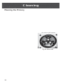
1
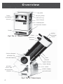
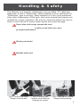
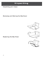
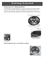
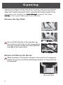
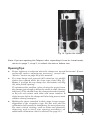
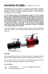
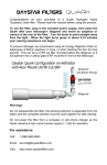
THE TELEPORT
is designed and hand-crafted by
Tom Noe
972-442-5456
[email protected]
4030 N. Hwy 78, Wylie, TX 75098
Owners Manual 2.1 © Teleport, 2001
Manual Design: Linda Silas, The Annex Studios
972-429-1636, www.annexstudios.com
2
TELEPORT 10”
The Telescoping Telescope
Owners Manual 2.1
PG
CONTENTS
4 Overview
5 Handling & Safety
6 Unpacking
7 Getting Started
8 Opening
10 Closing
11 Collimation
12 The Finder
14 Eyepieces
16 Observing
18 Electrical
20 Cleaning
22 Service
23 Specifications
As you read through this manual, watch for the following symbols:
Caution!
➤
Tip
Note:
Observation
Enclosed with your telescope you will also find a user’s manual for the
Protostar Diagonal Mount Assembly used in the Teleport.
3
Overview
top plate
finder
baseplate
carrying strap
shroud
strut clamps
altitude ring
serial# plate
accessories drawer
finder
spider
Fig1: The 10” Teleport closed
finder
secondary
mirror
eyepiece
focuser
friction damper
alititude ring
strut
altitude bearing
shroud
upper clamp
lower clamp
primary
mirror cell
cover
power supply
accessories
drawer
ground board
Fig 2: The 10” Teleport open
4
Handling & Safety
The Teleport is a precise, lightweight, very portable 10” reflecting
telescope. It has a “Newtonian” optical system and an altazimuth or
“Dobsonian” type mounting. Many aspects of it are more advanced
than other telescopes of this type, and some special techniques are
needed for proper operation. Be sure to read and follow the instructions in this manual to insure best results and avoid damage.
Never aim a telescope toward the sun! This is extremely
dangerous. A 10” mirror gathers about 1,000 times as much
light as your eye, and a split-second look can cause
permanent blindness. Never attempt to view the sun
unless you understand the procedures and have fitted the
Teleport aperture with a proper solar filter. Never place any
telescope so sunlight can strike the mirror, now or as the
earth turns. This can focus the sun’s heat in the scope
causing serious damage and possibly fire.
Watch your back! The Teleport is lightweight for a 10”
telescope. Still, it should be handled with appropriate care,
especially if you have any physical limitations, such as a
back problem. Use proper lifting techniques: lift with your
legs, not your back, and avoid bending or twisting in an
awkward way.
Handle with care! The Teleport is a precision optical
instrument. Always keep it upright unless following instructions in this manual requiring otherwise. When open the
Teleport may be carried with one hand (Fig 3). For greater
control, open or closed, it should be carried with both hands
by the altitude rings (Fig 4). The strap on the top plate (Fig
5) is only for carrying the closed scope when walking. Never
swing the scope by this strap or pull sideways on it! This
could pull the plate loose, causing the telescope to fall.
When handling it in a manner that requires sideways
movement, such as climbing steps or placing it onto a car
seat, grasp the scope securely with both hands, one in each
altitude ring. Openings in the cover are provided under the
side tabs. Always lower it gently onto hard surfaces.
Fig 3: Carrying the open
Teleport one-handed
Fig 4: Carrying the
Teleport by the altitude
bearings for control
Fig 5: Carrying the closed
Teleport while walking
5
Unpacking
Unpacking your scope
1.
2.
3.
With the box flaps open and the top foam pad removed, orient the box
so the Teleport logo on the top of the cover is right-reading.
Slide a hand down each side about two inches and insert your fingers
below the cover flaps and into the altitude rings (see Fig 4, page 5)
Grasp both rings firmly, lift the Teleport straight up out of the box and
set it down gently.
Removing and Storing the Slip Cover
The Teleport cover is designed to protect your telescope from sun,
airborne particulates and dew or brief, light rain. It is not intended to
withstand prolonged or heavy rain. If such conditions occur, move your
telescope to shelter.
1.
2.
3.
4.
5.
6.
7.
Pull the flaps around the top loose from
their velcro tabs and fold the top back.
Grasp the cover by the side openings and
lift it off.
Fold the body of the cover flat (Fig 6),
Fold in half along the corner seams (Fig 7).
Fold horizontally (Fig 8) up into the lid
Pull the top flaps around the folded body
and press the velcro tabs in place.
Align the folded cover on the lower front
of the scope and press it onto the velcro
strip provided.
Fig 6
Replacing the Slip Cover
1.
2.
2.
6
Pull the cover away from the velcro, unfold
it and orient it over the scope.
With the lid up, slide it onto the scope until
the straps rest on the top plate. Close the
lid and press the velcro tabs in place on
front and sides
The top may be lifted to access the handle
for straight level carrying. The side tabs
allow access to the altitude rings for more
controlled movement such as in and out of a
vehicle, through doorways, on stairs, etc.
Fig 7
Fig 8
Getting Started
Unlocking from “Shipping Mode”
The Teleport is simply closed for routine transport and opened again
for use. When it was packed for shipping, the primary mirror was
“locked” and must be “unlocked” before first use.This will take some
time, but will also familiarize you with many details of your new scope
You will need a philips screwdriver and 3/8” wrench.
1.
Open the scope per the instructions on
top centerpost
collimation
pages 8 & 9, then unlock the mirror as
screw
knobs
follows.
2. Turn each of the three white collimation
knobs (see Fig 9) two full turns CCW.
3. Remove the mirror cell following steps 14 on page 20, then return to step 4 below.
4. Place the cell carefully on a table,
mirror up. It will be covered by a solid
plate with three tabs (Fig 10).
sling
counterweights
screws
5. Remove the screws holding the tabs to
Fig 9: The mirror cell
the cell posts, and remove the plate.
6. Slide the cell so the top-post screw just
overhangs the table edge for access.
7. Hold the top center post screw with a philips
screwdriver and loosen its nut about a turn with
the wrench (Fig 11).
8. Turn the screw CCW almost 1/2 turn so
its small edge notch is at the top. Hold
it there with the screwdriver while
retightening the nut with the wrench.
Fig 10: Remove the
This orients the eccentric post so it no
mirror lock plate
longer presses against the mirror.
9. Holding the cell vertical behind the mirror box, plug in the
Fig 11: The
fan cord, then reinstall the cell and tighten all six screws.
top post
Check Adjustment of the Mirror Sling
Aim the scope about 30° up from horizontal and push forward on each of the black
triangles on the back of the mirror. The mirror should
move forward easily, then return when you release it. If
the mirror sticks at the top, the sling is too tight and is
holding the mirror against the top center post. If it sticks
at either bottom triangle, the sling is too loose, letting the
mirror rest on the lower posts. To adjust, loosen the lower
right cell post lock nut while holding the screw (Fig 12).
Turn the screw back and forth enough to raise and lower
the mirror. Hold it near the top of its travel range with
Fig 12: Adjust the sling
the screwdriver while retightening the lock nut.
7
Opening
Opening the Teleport takes less than a minute, once you are familiar
with the procedure. It’s very easy, but improperly performing some
steps can cause collimation error, reducing the image quality. It can
also cause poor stability, and even damage
damage. Practice the steps
exactly to form good habits right from the start.
Remove the Top Plate
1.
2.
3.
4.
Orient the scope to read the caution label on
the top plate.
Grasp inside the left altitude ring opening
with your left hand, and the left end of the
carrying strap with your right.
Keep the top plate horizontal, and pull your
two hands apart just enough for the top plate
to clear the slot in the left side of the rocker
box( Fig 12) when you push it to the right.
Tilt the left side of the top plate up just
enough to clear the top of the rocker box and
move the plate to the left until it is out of the
right slot (Fig 13).
Never tilt the left side of the top plate up
more than an inch (Fig 14). The tremendous
leverage you have on the slot could split the
top edge of the rocker box!
5.
Place the top plate on the right side of the
scope about an inch above the ground, align
the velcro, and press it in place.
Fig 12 - Yes
Fig 13 - Yes
Fig 14 - NO!
Extend and Clamp the Struts
When opening or closing the Teleport, never release it completely
unless at least one strut has both clamps locked, or it may fall and
be damaged!
1.
2.
3.
4.
8
Stand in front of the scope, facing the
power supply.
Insert the fingertips of both hands into the
top opening of the secondary cage and
grasp it at about 3 and 9 o’clock (Fig 15).
Lift up smoothly and evenly with both
hands, stretching the shroud and extending the scope to its full height.
Fig 15: Grasp the
secondary cage
Still holding the secondary cage up firmly
with your right hand fingertips, move your
left hand to grasp the left strut upper section and hold up on it.
5.
Continuing to lift firmly with your left
hand, almost enough to lift the scope from
the ground, tighten both left strut clamps
with your right (Fig 16).
6. Grasp the right strut upper section firmly
with your right hand, and again hold
upward enough to almost lift the scope.
7. Continuing to lift firmly with your right
hand, tighten both right strut clamps with
your left.
8. Rotate the scope 180o, and repeat steps 4,
5, & 6, again holding up firmly on the top
strut section so it is fully extended to its
stop while you tighten the clamps.
9. Move the finder from its storage position
to the secondary cage (see “Mounting” on
page 12)
10. Open the eyepiece drawer, place an
eyepiece fully into the focuser, and close
the drawer.
Fig 16: Tighten the clamps
The first time may take some doing, but with
practice it will become and quick and easy.
Note: If you are opening the Teleport after unpacking it from its travel mode,
return to page 7, step 2, to unlock the mirror before use.
OpeningTips
➤
Proper tightness is achieved when the clamps are turned horizontal. If wear
eventually makes adjustment necessary, consult the
“Service” section on page 22 of this manual.
➤
If a strut hangs and prevents full extension, its middle
section has rotated while the scope was closed (Fig 17).
Rotate it to align the top clamp over the bottom one (Fig
18), then finish opening.
To minimize this problem, when closing the scope loosen
the clamps just enough to allow the struts to slide (about a
half turn.) This should leave the clamps about horizontal,
so they do not contact each other and cause rotation. A
slight tension left in the clamps will also help prevent strut
rotation during transport.
➤
Holding the struts extended to their stops insures proper
alignment of the secondary cage. Do this well and the
collimation will usually be satisfactory for most observing.
For more critical viewing, such as lunar and planetary
observing, and to check your opening procedures, an
additional collimation check is advised (see page 11.)
Fig 17: Rotated
Fig 18: Aligned
9
Closing
Closing the Teleport is quite easy, but several small details will make a
difference. As with the opening procedure, perform the steps in a
precise and consistent way, practicing to make it easier and to
minimize the potential for an accident.
Prepare and Lower the Secondary Cage
1.
2.
3.
4.
5.
6.
7.
Aim the scope straight up, and turn it so the finder is facing you.
Remove the finder and clip it in the storage position.
Remove the eyepiece, place it in the drawer, and close the drawer.
Grasp the top section of the left strut with your left hand and loosen
its upper and lower clamps each 1/2 turn with your right.
Reverse hands and repeat step 4 for the right strut.
Rotate the scope 180o and repeat 4-5 for the other two struts. Be sure
to support the secondary cage by holding up on the top section of a
strut or on the secondary cage itself at all times.
Grasp the secondary cage inside its top opening with both hands and
lower it into the mirror box while keeping the scope pointed fully
vertical (the mirror box should stay against the rocker box front plate.)
A wiggle may sometimes be needed to help the struts retract fully.
Form the habit of always holding one of the upper strut sections.
Never release the upper cage after loosening the clamps until you
have lowered it gently into the mirror box!
Install the Top Plate
1.
2.
3.
4.
5.
6.
10
With the scope turned so the power supply faces you, grasp the top
plate at the lower end of its strap and lift it out, bottom first, from the
velcro on the side of the rocker box.
Hold it horizontal over the scope and rest its left edge on top of the
rocker box left side.
Align and insert its right edge into the right side rocker box slot. Use
the same caution here as when opening. Never pull up on the plate
while it is inserted into only one slot.
Grasp the left altitude ring through its opening and pull it to the left
while pulling the strap to the right just enough for the plate to clear
the left rocker box side.
Lower the left side of the plate to align with the slot and release the
rocker box side so it will close onto the plate.
Push the rocker box sides in to insure the plate is fully into both slots
before lifting the scope by its strap.
Collimation
Any optical system must be properly collimated for best image quality.
Collimation procedures can become a bit involved, as indicated by the
many articles and books in telescope literature. The design and
construction of the Teleport leaves only two variables that will normally need to be checked, namely the angles of both mirrors.
Laser Collimation
The fastest and easiest way to collimate your scope is with a Teleport
Laser Collimator or other laser collimation tool. Briefly, this procedure is:
1.
2.
➤
Insert the collimator into the focuser.
Adjust the secondary alignment screws so the laser spot falls inside
the ring in the center of the primary mirror.
3. Adjust the primary collimation screws so the returning beam falls
back onto the source in the center of the collimator face.
Details of this procedure are in the instructions for the Teleport Laser Collimator.
Other Collimation Tools
Collimation can also be done with optical tools, including a sight tube,
Cheshire eyepiece, and autocollimator. These are available from
Tectron Telescopes, 352-490-9101, http://www.amateurastronomy.com,
[email protected]. Details of the procedures for these
tools are in their manual and are also covered in the Protostar Diagonal Mount Assembly manual enclosed. Its diagrams show the visual
appearance of the mirrors before and after collimation.
Collimation and Opening
Become comfortable with collimation of the Teleport to take full
advantage of its high quality optics. Understanding the collimation
procedures will help point out any problems you may have with proper
opening techniques.
If you find after opening your scope, that the collimation is far off from
the last time it was used, chances are you failed to get one or more
struts fully extended either this time or the last. (Prior collimation may
have partially compensated for this error, but performance will never be
as good as if the scope is properly opened then collimated). If it appears
way off, loosen all 8 clamps and partially close the Teleport and re-open
it, being sure to reach full strut extension, before collimating.
➤
The feedback provided by a quick check of collimation after opening your scope
will help you perfect your opening technique. When you become proficient at
this, you will find that your scope’s collimation is very close every time. “Close”
means that the laser spots on both the primary mirror and the collimator face
are no more than a few millimeters from center.
11
The Finder
The Teleport’s Rigel Systems finder lets you easily place a particular
object or sky area in the eyepiece field. It is easier to use than conventional finder scopes that have a more limited field or a reversed
image, or both.
Mounting
1.
2.
3.
4.
With the Teleport open and vertical, stand behind it and locate the
finder in its storage position in the lower
rear opening of the rocker box.
At the left end of the finder, press the
button with your thumb and rock the
right end away from you to release it from
the baseplate (Fig 19)
Fig 19: Finder storage
Locate the other baseplate at the top edge
of the secondary cage. Hold the finder tilted 45° forward and slip the
front (long) tab into the forward slot in the baseplate.
While pressing the thumb button, rotate the finder toward the plate
and release the button so the clip locks into the slot at the rear of the
baseplate.
On/Off and Brightness
Turn the finder on by rotating the small black
knob on its lower front (Fig 20). It will click to
turn on, and will increase in brightness as it is
turned clockwise. At first, turn it fully clockwise and look through the opening near the
top of the finder so you see the two red rings.
Turn down the brightness to the lowest level
that lets you see the two red rings (1/2 and 2
Fig 20: Brightness control
degrees) against the sky you have. (Setting the
rings too bright can make it hard to see dim stars.)
Pulse
Adjust the small white knob (Fig 21), beside
the black brightness knob, to control the
duration of on- and off-time for pulsing, or set
for continuous on as you prefer. (I find that onand off-times of a few seconds let me see the
faintest stars while it’s off, and align accurately while it’s on.)
Fig 21: Pulse control
12
Finding Objects
Look directly at the star or other object, or the area of the sky you want
to aim at. Keeping both eyes open, move the Teleport so that the finder
comes between one eye and where you want to aim. Position it so the
object or area is centered in the circles.
Finder Alignment
1.
2.
3.
4.
5.
With a long focal length eyepiece (about 40mm if possible) in place,
follow the above procedure to aim the Teleport at a bright star. (Polaris
is good, since it moves so slowly through the field.)
Look through the eyepiece. If the star is not in the field, sweep the
scope in that area of the sky until it appears, and then center it.
Look through the finder with both eyes
open and adjust the three white screws
(Fig 22) to shift the red rings so the star is
centered. Use care to avoid moving the
scope when you do this.
Check the eyepiece field to see the star is
still centered, and repeat as needed.
To improve the alignment accuracy, change
to a medium power eyepiece (about 10mm)
and repeat the procedure.
Fig 22: Finder alignment
Storage
Be sure to remove the finder from the secondary cage baseplate and
place it on it’s storage baseplate before closing your scope.
Battery
The Rigel Finder uses a BR2032 or CR2032 three-volt lithium battery,
or equivalent. These are readily available in the photo departments of
department or electronics stores. To replace, remove the finder from its
base, push out the battery and slip in the new one, being careful to get
the polarity correct.
13
Eyepieces
The Teleport’s 2” focuser and 1.25” adapter allow the use of many
different eyepieces. Many types are available with a wide range of
features, quality and price. Over the past several years I have evaluated many of the better types for use with the Teleport. As a group, I
have found none as good overall as the Pentax XL series.
Pentax Eyepieces
Desirable attributes of the Pentax XL series include:
1.
2.
3.
4.
5.
6.
7.
Ideal selection of focal lengths in logical steps throughout the range.
Full 20mm eye relief in all focal lengths
Wide 65° apparent field of view—which I find ideal (the 28mm is 55°)
High brightness, contrast, and sharpness.
Weights closely matched throughout the entire set.
Parfocal to a very close tolerance.
Very effective, adjustable rubber eye cups.
Tradeoffs are cost and slight edge astigmatism, which I find acceptable.
The following table lists the focal lengths available, with their magnifications and fields with the Teleport:
Focal
Length
40.0 mm
28.0 mm
21.0 mm
14.0 mm
10.5 mm
7.0 mm
5.2 mm
Eye
Relief
20 mm
20 mm
20 mm
20 mm
20 mm
20 mm
20 mm
Apparent
Field
65°
55°
65°
65°
65°
65°
65°
Magnification
32 x
45 x
60 x
91 x
121 x
181 x
244 x
True
Field
2.04°
1.22°
1.08°
0.72°
0.54°
0.36°
0.27°
My usual set (Fig 23) includes the 40, 21, 10.5, and 5.2. For certain
objects, however, the 14 and
Pentax XL
the 7 are ideal. Seeing condiEyepieces
tions often preclude the use of
Red LED
the 5.2, so I sometimes substiFlashlight
tute the 7. It can be used a bit
Eyepiece
more often, but doesn’t provide
Heater
quite the detail of the 5.2 when
seeing is really good. The view
Laser
Collimator
through the 40mm is spectacular on extended objects. Its 2°
field is almost half that of
many finder scopes, making a
finder scope unneccessary.
Fig 23: My Accessories Drawer
14
Holding the Eyepiece in Place
The clamping screw can be inserted in any of three threaded holes in
the focuser. I don’t normally use it, as the nylon friction screw in the
focuser is more convenient. Set it to be just snug for your eyepieces.
Accomodating Other Eyepieces
Balance
Experienced observers may already have a preferred set of eyepieces.
Most of these can be used with the Teleport, though some may impose
problems. Wide variation in weight effects the balance, as with any
small scope. The Teleport is supplied with three balancing weights that
can be attached to the mirror cell on the bottom of the scope or to the
secondary cage on the top. For heavier eyepieces, you may need to place
one or more of the counterweights on the mirror cell. For very light
ones, you may need to place one or more on the secondary cage.
If the scope is still unbalanced, you can
increase the friction damping of the altitude
bearings by adjusting the screws above of the
altitude rings (Fig 24) wth the allen wrench.
Avoid excess tightening which would interfere with the smooth easy motion that is part
of the joy of using the Teleport.
Fig 24: adjusting
friction damping
Focal Plane Location
Most good eyepieces have a standard focal plane location, close to the
surface that seats onto the focuser. Unfortunately, some designs may
vary widely from this, requiring a large change in the focuser position.
The Teleport focuser has, of necessity, a limited range of travel. Additional out-travel can be effected by sliding the eyepiece partway out and
locking it with the screw.
If a 1.25” eyepiece you use frequently requires a lot of out-travel,
consider using an adapter that extends it. Also, a recessed adapter may
allow a 1.25” eyepiece to go farther in than the focuser top surface.
Within limits, custom adapters are possible in order to parfocalize
unmatched eyepieces. If you have a particular problem here, contact me
for a quote.
It is also possible to adjust the location of the Teleport’s focal plane in
relation to the focuser. This is done by adjustment of the strut positions, effectively changing the length of the scope. You should do this
only if you find it necessary for your overall set of eyepieces. It requires
time and care, and is not practical as a routine adjustment. If you are
certain you want to do this, see “Service” on page 22.
15
Observing
Every observer has favorite methods and objects. Many excellent
books are available to help the beginner become familiar with the sky
and learn the procedures for studying it. Here we present a few
suggestions regarding the use of the Teleport, leaving the broad view
of observing up to you and your chosen reference materials.
The Teleport is designed to give the observer a direct connection to the
universe, imposing a minimum of technology between the user and the
objects observed. Without digital readouts, “go-to” databases, etc., but
with smooth, easy motions, using it quickly becomes very intuitive. It’s
like looking directly at the object, but with a thousand times the light
grasp of the unaided eye, and with the magnification best for the object
to be viewed. Here are some tips:
Setup
Find a solid foundation
Always place the Teleport on a solid surface, such as the earth, gravel,
concrete, etc. Be sure each of the three feet rests on the surface, and
that the ground board between the feet does not. Tall grass will cause
instability, and a surface such as a wood deck may flex when anyone
moves on it, including when you shift your weight at the eyepiece.
Allow time for your mirror to reach thermal equilibrium.
While changing temperature, even a low-expansion Pyrex mirror
changes shape. The image quality will be poor until it stabilizes. This
can be a matter of a few minutes, but can be more under extreme
changes. The thin mirror and open air flow of the Teleport minimize
this, and the fan can reduce the equilibration time still more. Nothing
can eliminate it completely.
Sky Conditions
Get to the darkest site you can.
Take advantage of the portability of the Teleport. Of course there will
be times you may want to observe in areas of substantial light pollution. Artificial lights and the moon still allow reasonable viewing of
bright objects like planets and the moon, but will greatly diminish your
ability to see those dim “faint fuzzies.” Filters can help.
Learn to work with the sky conditions that exist.
What you view, and the magnification you can use effectively will
generally be limited by the “seeing” at the time. Upper atmospheric
cells of varying temperatures bend the light passing through them,
causing the image to shimmer, or just blur without apparent movement. Lower magnification will be required when seeing is poor. Expect
to use high powers, (above 120x) a limited percentage of the time,
depending on your observing site, season, frontal passages, etc.
16
Viewing
Begin with lower power.
If you are not an experienced observer, use eyepieces in the 20-40 mm
focal length range to make finding objects easier. The wider field is
more likely to contain what you are looking for, and moving the scope
while viewing is much less critical.
Learn “which way is up”.
Newtonian optical systems produce an inverted and reversed image, so
when you move the scope, the image moves the opposite way. Think of
it as pushing the object, not the scope, and you will quickly adjust to
the reverse motions.
Learn to follow as the earth turns.
Objects will follow circular paths east to west. Remember that your
scope will need to move in that same direction to keep them in view.
Learn to move the scope along both axes as needed so that when you
release it, the object will slowly drift through the center of the field as
the earth rotates.
Areas of the Sky
Images of objects nearer the horizon will be adversely affected by the
increased travel of the light through the atmosphere. Objects are best
when viewed higher in the sky.
A special situation exists with the sky area directly overhead. This is
often referred to by users of altazimuth telescopes as “Dobson’s Hole”.
Movement of a telescope about it’s vertical (azimuth) axis is more
difficult here than other parts of the sky because the lever arm used to
turn it in azimuth is almost zero. Learn to twist, rather than push the
scope in this part of the sky, and you will reduce the difficulty. A firm
grasp in the opening of the secondary cage will help.
Recommended References
Nightwatch by Terrence Dickinson (Camden House; Camden East,
Ontario; revised edition, 1993)
The Sky: A User’s Guide by David H. Levy (Cambridge; New York;
1991)
The Universe From Your Backyard by David J. Eicher (Cambridge;
New York; 1988)
The Backyard Astronomer’s Guide by Terrence Dickinson & Alan
Dyer (Camden House; Camden East, Ontario; 1991)
17
Electrical
Power Supply
Your Teleport is equipped with a power supply, fan, and secondary and
eyepiece heaters. These enhance your observing under certain conditions by quicker temperature equilibration of the primary mirror and
reduction of dew formation problems.
The power supply is in the front of the mirror box. It contains 6 “C” size
alkaline batteries. These are readily available and offer maximum
energy relative to weight and cost. They will run the mirror fan about
100 hours, the secondary heater about 40, and the eyepiece heater
about 20. Keep these numbers in mind for an idea of when you may
need to replace them. A spare set is recommended.
Sliding switches on the face of the power supply turn on the fan and
secondary heat when slid toward the outside of the scope. Always slide
them back toward center when not needed. Leaving either on when
storing your scope will deplete the batteries. The external outlet in the
front of the power supply is for a standard Kendrick eyepiece heater.
Changing Batteries
1.
2.
3.
4.
5.
6.
7.
18
four philips screws
To remove the power supply, loosen
the four philips screws at the
corners (Fig 25).
Tilt the power supply and pull it
out slightly to access the cords from
the mirror fan and secondary
heater, and unplug them.
Fig 25: Power Supply Cover
The batteries are held securely in
place by a cover that also stops
reflections. Peel away the side of the
cover opposite where the cables
were plugged (Fig 26).
Remove the batteries and replace
with fresh “C” size alkalines, in
proper orientation as shown.
Replace the cover and seal its edge
securely. The cover helps prevent
the batteries from being dislodged
during handling or transport.
Fig 26: Removing Batteries
Hold the supply close to the opening
and plug in the cords.
Replace the supply and install the four screws.
Mirror Fan
The mirror fan speeds up the cooling or warming of the primary mirror
when the Teleport has been stored in warmer or colder conditions.
While changing temperature, the mirror will distort, reducing image
quality. If you wish to observe right away, switch the fan on when you
set up the scope. If the temperature change is very small or you won’t
observe until much later, leave it off. The fan will actually increase the
amount of mirror distortion at first, since it increases its rate of temperature change. The benefit is that it approaches final temperature
and full image quality in less time. Turn the fan off once the mirror is
stabilized, usually a quarter to a half hour but possibly longer with
large changes in temperature. If a sudden change in temperature
occurs while observing, the fan may be used again as needed.
Secondary Heat
Atmospheric conditions will often cause dew to form on surfaces at
night, especially those able to radiate their heat toward the dark sky. If
this seems imminent, switch the secondary heat on before dew begins
to form. Once significant dew has formed on the secondary, considerable time may be needed to remove it. Under light dew conditions,
operate the heater only part time to conserve the batteries. A red LED
in the spider hub indicates when the heater is on.
Eyepiece Heater
Dew may also form on eyepieces or on the
finder beam plate. A Kendrick eyepiece heater
may be wrapped snugly around the eyepiece
(Fig 27), moving it part time to the finder if
needed. (The finder element may also be
wiped gently with tissue if needed. It is not an
expensive optical surface like the secondary
mirror or eyepiece.)
Fig 27: heating the
eyepiece
The eyepiece heater is on when it is plugged
in, so do not leave it plugged in when not
needed (its power draw is much higher than the secondary heater or
fan.) If dewing is heavy and you are using more than one eyepiece, it
may help to keep those not in use in your pocket (31mm Naglers may
not fit).
19
Cleaning
Cleaning the Primary
Protect your mirror by keeping your telescope closed when not in use,
so that cleaning will be needed very infrequently. Over time, you will
see an accumulation of dirt, but it will have less effect on the image
quality than you would expect. (Under some lighting conditions, such
as with a flashlight aimed at the mirror in the dark, even a fairly clean
mirror can look terrible.)
With proper care, cleaning should be needed only after extended use.
When finally required, proceed as as follows:
1.
2.
3.
4.
5.
6.
7.
8.
9.
10.
11.
12.
13.
14.
15.
20
Open the Teleport, place an eyepiece in the focuser for balance, and tilt
the scope almost horizontal.
Place a support under the secondary cage and tilt the scope until the
cage rests on it. (When the mirror is
removed, the scope will be unbalanced
six mirror-cell screws
and could fall.)
With a philips screwdriver, remove the
six screws holding the mirror cell (Fig
28). Be sure to hold the cell securely
while removing the last ones.
Lift the cell away enough to reach into
the mirror box, and unplug the fan cord.
Place the cell on a table and blow loose
dust away with clean compressed air.
If the air cleaning proves sufficient, skip
Fig 28: Mirror cell
to step 19.
If washing is required, first slide the cell so the top post overhangs the
edge of the table about an inch.
Loosen it's lock nut fully so the post is loose.
Peel the strap loose from the tape on the mirror edge, tilt the top post
slightly, and lift the mirror out. (The three support triangles will
remain attached to the back of the mirror)
Place it face up in a clean sink and run warm water to cover it.
Prepare a cleaning solution of three drops of mild hand dishwashing
detergent in about a cup of warm water. Stir thoroughly to dissolve the
detergent.
Pour most of the cleaning solution over the mirror surface.
Dip a cotton ball in the remaining cleaning solution and swab the
mirror surface gently in a circular motion. Work from the center to the
edge, being sure to not miss any of it.
Rinse thoroughly with running warm water, lifting and tilting the
mirror to rinse the back, then finally the front surface again.
Pour a cup or so of distilled water over the surface then drain it off and
stand the mirror on edge on a clean towel.
16. If you have a source of clean dry air, blow the water off the mirror,
including the rear triangles. If you don't have the air source, allow the
mirror to stand until dry.
17. Replace the mirror in the cell in its original orientation (serial number
at the top) and press the strap tape against the mirror edge.
18. Install the top post, orient it with the screw head mark to the outside,
and tighten the nut.
19. Hold the cell near the rear of the mirror box and plug in the fan cord.
20. Align the posts with the holes in the mirror box opening and place the
cell flat against the rear of the box with the screw holes aligned.
21. Install the six screws, leaving them slightly loose until all are started.
22. Tighten the six screws until snug.
23. Check the mirror sling adjustment per page 7.
24. Collimate per the instructions on page 11.
Cleaning the Secondary
(Refer also to the Protostar Manual included with your Teleport)
1.
2.
3.
4.
5.
6.
7.
8.
9.
10.
11.
12.
13.
14.
Loosen the secondary mount center nut a turn with a 9/16"wrench.
Hold the secondary mirror assembly with one hand and remove the
nut with the other.
Slide the assembly down enough to allow access to the tiny heater wire
connector between the mount and the spider hub and unplug it.
Remove the assembly completely from the scope.
Hold the assembly so the mirror surface is horizontal, facing up, and
remove the two shroud screws.
Slide the shoud off, then lift the mirror away from its mount.
The back surface of the mirror will be coated with heat transfer
compound. Scrape it off the mirror and return it to the center opening
of the foam pad. Don’t get it on the mirror surface.
Wipe any remaining compound from the back of the mirror.
Clean and dry per the same procedure as the primary.
Place the clean, dry mirror onto the heat ransfer compound on the pad.
Slide the shroud on so its rim is just snug on the mirror edge, as it was
before removal. Insert and tighten the two shroud screws
Slide the mount stem through the spider hub and to plug in the heater
connector. Rotate the assembly carefully to tuck the wire between the
hub and mirror mount and align the three detents in the clutch plate
with the three collimation screws.
Install the lock nut and tighten gently with the wrench, about 1/6 turn
beyond finger tight.
Collimate the scope per the instructions on page 11.
21
Service
Instructions for some procedures follow. For other service questions,
just send an email or give me a call!
Cleaning
Clean the optics only when really necessary, following the instructions
in the prior section.
Wipe the laminated bearing surfaces and the remainder of the scope
with a damp cloth, then a clean, dry one.
Nuts and Bolts
Periodically check all fasteners for proper tightness to insure stability
and top performance. Do not overtighten screws, particularly those
threaded into the Apple Ply structures.
Strut Clamp Adjustment
It is desirable that the strut clamp knobs are at a right angle to the
strut when properly tight. With wear, this may change, and can easily
be adjusted.
1.
2.
3.
4.
5.
Note which direction and how far you wish the knob to be turned.
With the strut extended, loosen the knob about 5 turns.
Push the knob in against the spring so the hex head of the screw is out
of its socket.
Rotate the knob and screw together one or more flats on the hex.
Tighten the knob and check. Repeat the above steps if needed.
Strut Length Adjustment
If you use eyepieces with a focal plane location far from the eyepiece
seating surface, you may exceed the adjustment range of the focuser.
That may be moved a few millimeters by shifting the strut locations.
Do this only if really necessary, and do not be tempted to change it
routinely. It must be carefully done, matching the location of all struts
to keep the scope square.
A strut may be shifted slightly by loosening the 4 set screws holding the
bottom section in the mirror box. The range of movement is very
limited. Do not move the bottom of the strut section higher than the
bottom surface of the mirror box. Do not extend it more than about
9mm below the bottom to avoid interference with the plate in the rocker
box. Use a gauge to match the positions, and retighten all four screws.
Do not overtighten! This could bend the struts.
22
Specifications
Dimensions
14.5"w x 14"d x 26"h
Primary
Structures
Apple Ply, 3-12mm
Finish
Polane T catalyzed polyurethane coating
Other
Structures
Delrin acetal, ABS, Teflon, laminate,
lycra spandex, etc.
Weight
32lb.
Primary
Mirror
10" F/5 fine annealed Pryex, 10:1
Zambuto Optical serial#_____________
Mirror Cell
9-point Delrin acetal
Secondary
Mirror
Protostar 1.83" elliptical flat
with enhanced Al coating
Focuser
Teleport 2" helical, 1.25" adapter
Finder
Rigel Systems unit-power LED
Cover
200D coated nylon and polyethylene
Batteries
Main Power Supply: 6 "C" size alkaline
Finder: 1 BR2032 or CR2032 3V Li
23
TELEPORT
972-442-5456
[email protected]
4030 N. Hwy 78, Wylie, TX 75098