1
8931021.BK Page i Thursday, August 14, 1997 12:08 PM
Installation and
Reference for the
BayStack 150-series
Ethernet Hubs
Part No. 893-01021-A
June 1997
8931021.BK Page ii Thursday, August 14, 1997 12:08 PM
4401 Great America Parkway
Santa Clara, CA 95054
8 Federal Street
Billerica, MA 01821
© 1997 by Bay Networks, Inc. All rights reserved.
Bay Networks and Optivity are registered trademarks of Bay Networks, Inc.
Bay Networks Press and BayStack are trademarks of Bay Networks, Inc.
Other brand and product names are registered trademarks or trademarks of their respective holders.
Statement of Conditions
In the interest of improving internal design, operational function, and/or reliability, Bay Networks, Inc. reserves the
right to make changes to the products described in this document without notice.
Bay Networks, Inc. does not assume any liability that may occur due to the use or application of the product(s) or
circuit layout(s) described herein.
Portions of the code in this software product are Copyright © 1988, Regents of the University of California. All rights
reserved. Redistribution and use in source and binary forms of such portions are permitted, provided that the above
copyright notice and this paragraph are duplicated in all such forms and that any documentation, advertising materials,
and other materials related to such distribution and use acknowledge that such portions of the software were
developed by the University of California, Berkeley. The name of the University may not be used to endorse or
promote products derived from such portions of the software without specific prior written permission.
SUCH PORTIONS OF THE SOFTWARE ARE PROVIDED “AS IS” AND WITHOUT ANY EXPRESS OR
IMPLIED WARRANTIES, INCLUDING, WITHOUT LIMITATION, THE IMPLIED WARRANTIES OF
MERCHANTABILITY AND FITNESS FOR A PARTICULAR PURPOSE.
In addition, the program and information contained herein are licensed only pursuant to a license agreement that
contains restrictions on use and disclosure (that may incorporate by reference certain limitations and notices imposed
by third parties).
RESTRICTED RIGHTS LEGEND: Use, duplication, or disclosure by the U.S. Government is subject to the
restrictions set forth in subparagraph (c)(1) of the Commercial Computer Software—Restricted Rights clause of
FAR52.227-19 or subparagraph (c)(1)(a) of the Rights in Technical Data and Computer Software clause of DFARS
52.227-7013, and any successor rules or regulations, whichever is applicable.
Federal Communications Commission (FCC) Statement
Note: This equipment has been tested and found to comply with the limits for a Class A digital device, pursuant to Part
15 of the FCC rules. These limits are designed to provide reasonable protection against harmful interference when the
equipment is operated in a commercial environment. This equipment generates, uses, and can radiate radio frequency
energy. If it is not installed and used in accordance with the instruction manual, it may cause harmful interference to
radio communications. Operation of this equipment in a residential area is likely to cause harmful interference, in
which case users will be required to take whatever measures may be necessary to correct the interference at their own
expense.
EN 55 022 Declaration of Conformance
This is to certify that the Bay Networks BayStack 150-series hubs are shielded against the generation of radio
interference in accordance with the application of Council Directive 89/336/EEC, Article 4a. Conformity is declared
by the application of EN 55 022 Class A (CISPR 22).
ii
893-01021-A
8931021.BK Page iii Thursday, August 14, 1997 12:08 PM
Warning: This is a Class A product. In a domestic environment, this product may cause radio
interference, in which case, the user may be required to take appropriate measures.
Voluntary Control Council for Interference (VCCI) Statement
This equipment is in the first category (information equipment to be used in commercial and/or industrial areas) and
conforms to the standards set by the Voluntary Control Council for Interference by Data Processing Equipment and
Electronic Office Machines that are aimed at preventing radio interference in commercial and/or industrial areas.
Consequently, when this equipment is used in a residential area or in an adjacent area thereto, radio interference may
be caused to equipment such as radios and TV receivers.
Bay Networks, Inc. Software License Agreement
NOTICE: Please carefully read this license agreement before copying or using the accompanying software or
installing the hardware unit with pre-enabled software (each of which is referred to as “Software” in this Agreement).
BY COPYING OR USING THE SOFTWARE, YOU ACCEPT ALL OF THE TERMS AND CONDITIONS OF THIS
LICENSE AGREEMENT. THE TERMS EXPRESSED IN THIS AGREEMENT ARE THE ONLY TERMS UNDER
WHICH BAY NETWORKS WILL PERMIT YOU TO USE THE SOFTWARE. If you do not accept these terms and
conditions, return the product, unused and in the original shipping container, within 30 days of purchase to obtain a
credit for the full purchase price
1. License Grant. Bay Networks, Inc. (“Bay Networks”) grants the end user of the Software (“Licensee”) a personal,
nonexclusive, nontransferable license: a) to use the Software either on a single computer or, if applicable, on a single
authorized device identified by host ID, for which it was originally acquired; b) to copy the Software solely for backup
purposes in support of authorized use of the Software; and c) to use and copy the associated user manual solely in
support of authorized use of the Software by Licensee. This license applies to the Software only and does not extend
to Bay Networks Agent software or other Bay Networks software products. Bay Networks Agent software or other
Bay Networks software products are licensed for use under the terms of the applicable Bay Networks, Inc. Software
License Agreement that accompanies such software and upon payment by the end user of the applicable license fees
for such software.
2. Restrictions on use; reservation of rights. The Software and user manuals are protected under copyright laws.
Bay Networks and/or its licensors retain all title and ownership in both the Software and user manuals, including any
revisions made by Bay Networks or its licensors. The copyright notice must be reproduced and included with any
copy of any portion of the Software or user manuals. Licensee may not modify, translate, decompile, disassemble, use
for any competitive analysis, reverse engineer, distribute, or create derivative works from the Software or user
manuals or any copy, in whole or in part. Except as expressly provided in this Agreement, Licensee may not copy or
transfer the Software or user manuals, in whole or in part. The Software and user manuals embody Bay Networks’ and
its licensors’ confidential and proprietary intellectual property. Licensee shall not sublicense, assign, or otherwise
disclose to any third party the Software, or any information about the operation, design, performance, or
implementation of the Software and user manuals that is confidential to Bay Networks and its licensors; however,
Licensee may grant permission to its consultants, subcontractors, and agents to use the Software at Licensee’s facility,
provided they have agreed to use the Software only in accordance with the terms of this license.
893-01021-A
iii
8931021.BK Page iv Thursday, August 14, 1997 12:08 PM
3. Limited warranty. Bay Networks warrants each item of Software, as delivered by Bay Networks and properly
installed and operated on Bay Networks hardware or other equipment it is originally licensed for, to function
substantially as described in its accompanying user manual during its warranty period, which begins on the date
Software is first shipped to Licensee. If any item of Software fails to so function during its warranty period, as the sole
remedy Bay Networks will at its discretion provide a suitable fix, patch, or workaround for the problem that may be
included in a future Software release. Bay Networks further warrants to Licensee that the media on which the
Software is provided will be free from defects in materials and workmanship under normal use for a period of 90 days
from the date Software is first shipped to Licensee. Bay Networks will replace defective media at no charge if it is
returned to Bay Networks during the warranty period along with proof of the date of shipment. This warranty does not
apply if the media has been damaged as a result of accident, misuse, or abuse. The Licensee assumes all responsibility
for selection of the Software to achieve Licensee’s intended results and for the installation, use, and results obtained
from the Software. Bay Networks does not warrant a) that the functions contained in the software will meet the
Licensee’s requirements, b) that the Software will operate in the hardware or software combinations that the Licensee
may select, c) that the operation of the Software will be uninterrupted or error free, or d) that all defects in the
operation of the Software will be corrected. Bay Networks is not obligated to remedy any Software defect that cannot
be reproduced with the latest Software release. These warranties do not apply to the Software if it has been (i) altered,
except by Bay Networks or in accordance with its instructions; (ii) used in conjunction with another vendor’s product,
resulting in the defect; or (iii) damaged by improper environment, abuse, misuse, accident, or negligence. THE
FOREGOING WARRANTIES AND LIMITATIONS ARE EXCLUSIVE REMEDIES AND ARE IN LIEU OF ALL
OTHER WARRANTIES EXPRESS OR IMPLIED, INCLUDING WITHOUT LIMITATION ANY WARRANTY OF
MERCHANTABILITY OR FITNESS FOR A PARTICULAR PURPOSE. Licensee is responsible for the security of
its own data and information and for maintaining adequate procedures apart from the Software to reconstruct lost or
altered files, data, or programs.
4. Limitation of liability. IN NO EVENT WILL BAY NETWORKS OR ITS LICENSORS BE LIABLE FOR ANY
COST OF SUBSTITUTE PROCUREMENT; SPECIAL, INDIRECT, INCIDENTAL, OR CONSEQUENTIAL
DAMAGES; OR ANY DAMAGES RESULTING FROM INACCURATE OR LOST DATA OR LOSS OF USE OR
PROFITS ARISING OUT OF OR IN CONNECTION WITH THE PERFORMANCE OF THE SOFTWARE, EVEN
IF BAY NETWORKS HAS BEEN ADVISED OF THE POSSIBILITY OF SUCH DAMAGES. IN NO EVENT
SHALL THE LIABILITY OF BAY NETWORKS RELATING TO THE SOFTWARE OR THIS AGREEMENT
EXCEED THE PRICE PAID TO BAY NETWORKS FOR THE SOFTWARE LICENSE.
5. Government Licensees. This provision applies to all Software and documentation acquired directly or indirectly
by or on behalf of the United States Government. The Software and documentation are commercial products, licensed
on the open market at market prices, and were developed entirely at private expense and without the use of any U.S.
Government funds. The license to the U.S. Government is granted only with restricted rights, and use, duplication, or
disclosure by the U.S. Government is subject to the restrictions set forth in subparagraph (c)(1) of the Commercial
Computer Software––Restricted Rights clause of FAR 52.227-19 and the limitations set out in this license for civilian
agencies, and subparagraph (c)(1)(ii) of the Rights in Technical Data and Computer Software clause of DFARS
252.227-7013, for agencies of the Department of Defense or their successors, whichever is applicable.
6. Use of Software in the European Community. This provision applies to all Software acquired for use within the
European Community. If Licensee uses the Software within a country in the European Community, the Software
Directive enacted by the Council of European Communities Directive dated 14 May, 1991, will apply to the
examination of the Software to facilitate interoperability. Licensee agrees to notify Bay Networks of any such
intended examination of the Software and may procure support and assistance from Bay Networks.
7. Term and termination. This license is effective until terminated; however, all of the restrictions with respect to
Bay Networks’ copyright in the Software and user manuals will cease being effective at the date of expiration of the
Bay Networks copyright; those restrictions relating to use and disclosure of Bay Networks’ confidential information
shall continue in effect. Licensee may terminate this license at any time. The license will automatically terminate if
Licensee fails to comply with any of the terms and conditions of the license. Upon termination for any reason,
Licensee will immediately destroy or return to Bay Networks the Software, user manuals, and all copies. Bay
Networks is not liable to Licensee for damages in any form solely by reason of the termination of this license.
iv
893-01021-A
8931021.BK Page v Thursday, August 14, 1997 12:08 PM
8. Export and Re-export. Licensee agrees not to export, directly or indirectly, the Software or related technical data
or information without first obtaining any required export licenses or other governmental approvals. Without limiting
the foregoing, Licensee, on behalf of itself and its subsidiaries and affiliates, agrees that it will not, without first
obtaining all export licenses and approvals required by the U.S. Government: (i) export, re-export, transfer, or divert
any such Software or technical data, or any direct product thereof, to any country to which such exports or re-exports
are restricted or embargoed under United States export control laws and regulations, or to any national or resident of
such restricted or embargoed countries; or (ii) provide the Software or related technical data or information to any
military end user or for any military end use, including the design, development, or production of any chemical,
nuclear, or biological weapons.
9. General. If any provision of this Agreement is held to be invalid or unenforceable by a court of competent
jurisdiction, the remainder of the provisions of this Agreement shall remain in full force and effect. This Agreement
will be governed by the laws of the state of California.
Should you have any questions concerning this Agreement, contact Bay Networks, Inc., 4401 Great America Parkway,
P.O. Box 58185, Santa Clara, California 95052-8185.
LICENSEE ACKNOWLEDGES THAT LICENSEE HAS READ THIS AGREEMENT, UNDERSTANDS IT,
AND AGREES TO BE BOUND BY ITS TERMS AND CONDITIONS. LICENSEE FURTHER AGREES THAT
THIS AGREEMENT IS THE ENTIRE AND EXCLUSIVE AGREEMENT BETWEEN BAY NETWORKS AND
LICENSEE, WHICH SUPERSEDES ALL PRIOR ORAL AND WRITTEN AGREEMENTS AND
COMMUNICATIONS BETWEEN THE PARTIES PERTAINING TO THE SUBJECT MATTER OF THIS
AGREEMENT. NO DIFFERENT OR ADDITIONAL TERMS WILL BE ENFORCEABLE AGAINST BAY
NETWORKS UNLESS BAY NETWORKS GIVES ITS EXPRESS WRITTEN CONSENT, INCLUDING AN
EXPRESS WAIVER OF THE TERMS OF THIS AGREEMENT.
893-01021-A
v
8931021.BK Page vi Thursday, August 14, 1997 12:08 PM
vi
893-01021-A
8931021.BK Page vii Thursday, August 14, 1997 12:08 PM
Contents
Preface
Purpose ........................................................................................................................... xv
Audience .......................................................................................................................... xv
Conventions .....................................................................................................................xvi
Special Message Formats .........................................................................................xvi
Two-tiered Procedure Format ....................................................................................xvi
Use of Enter, Type, and Press ...................................................................................xvi
Other Conventions ...................................................................................................xvii
Related Publication .........................................................................................................xvii
Ordering Bay Networks Publications ..............................................................................xvii
Bay Networks Customer Service ................................................................................... xviii
How to Get Help ............................................................................................................ xviii
For More Information .......................................................................................................xix
Chapter 1
Introduction
Overview .........................................................................................................................1-1
Features .........................................................................................................................1-2
Physical Description .......................................................................................................1-4
Front Panel ...............................................................................................................1-4
RJ-45 10BASE-T Ethernet Ports .......................................................................1-5
MDI and MDI-X Switch ......................................................................................1-5
LED Indicators ...................................................................................................1-5
Rear Panel ...............................................................................................................1-8
Cascade Connectors .........................................................................................1-8
Communications Port ........................................................................................1-8
AUI Port .............................................................................................................1-9
Removable Power Supply ..................................................................................1-9
893-01021-A
vii
8931021.BK Page viii Thursday, August 14, 1997 12:08 PM
Chapter 2
Planning the Network Configuration
Building Hub Stacks .......................................................................................................2-1
Ethernet Rules .........................................................................................................2-2
Hub Roles .......................................................................................................................2-2
Position in the Stack .................................................................................................2-2
Managed Hub Roles ..........................................................................................2-2
Unmanaged Hub Roles .....................................................................................2-3
Hub ID Numbers .............................................................................................................2-4
Cascading Hubs into a Hub Stack ..................................................................................2-4
Chapter 3
Installation
Package Contents ..........................................................................................................3-1
Operating Environment ...................................................................................................3-2
Power Specifications ......................................................................................................3-2
Installing the Hub on a Flat Surface ...............................................................................3-2
Installing the Hub in a Rack ............................................................................................3-3
Cascading Hubs .............................................................................................................3-3
Network Connections .....................................................................................................3-4
Connecting Stations to the Hub ...............................................................................3-4
Daisy Chaining Hub Stacks ......................................................................................3-5
Using Twisted Pair Cable for Cascading ..................................................................3-6
Using the AUI Port for Cascading ............................................................................3-6
Using Thin Coaxial Cable for Cascading ...........................................................3-7
Using Thick Coaxial Cable for Cascading ..........................................................3-7
Using Fiber Optic Cable for Cascading .............................................................3-8
Completing the Installation .............................................................................................3-8
Checking the Diagnostic Displays ..................................................................................3-9
Troubleshooting ..............................................................................................................3-9
viii
893-01021-A
8931021.BK Page ix Thursday, August 14, 1997 12:08 PM
Chapter 4
Initializing the
Network Management Module
Understanding the NMM Booting and Initializing Process ..............................................4-1
Initializing the NMM to Boot Remotely ............................................................................4-2
Setting up the BootP/load Server .............................................................................4-3
Connecting to the Communications Port ........................................................................4-4
Starting the Booting Process and Initializing the NMM ..................................................4-5
Using the Telnet Protocol to Access the Configuration Menu .......................................4-10
Chapter 5
Using the Configuration Menus
Accessing the NMM Configuration Menus .....................................................................5-1
About the Configuration Menus ......................................................................................5-2
Reading Module Information Displays .....................................................................5-3
Reading Error and Status Messages .......................................................................5-3
Executing Commands ..............................................................................................5-3
Boot Configuration Menus and Commands ....................................................................5-4
Boot Main Menu .......................................................................................................5-5
Boot System Configuration Menu ......................................................................5-6
Boot File Configuration Menu ............................................................................5-6
Boot IP Configuration Menu ..............................................................................5-7
Runtime Configuration Menus and Commands ..............................................................5-7
Runtime Main Menu .................................................................................................5-9
Runtime Boot Configuration Menu ..................................................................5-10
Runtime System Configuration Menu ..............................................................5-11
Runtime Protocol Configuration Menu .............................................................5-11
Runtime Boot File Configuration Menu ............................................................5-12
Runtime Profile Configuration Menu ................................................................5-13
Runtime Port Selection Table Menu .................................................................5-14
Runtime SNMP Configuration Menu ................................................................5-15
893-01021-A
ix
8931021.BK Page x Thursday, August 14, 1997 12:08 PM
Appendix A
Technical Specifications
General Specifications ................................................................................................... A-1
Declaration of Conformity .............................................................................................. A-3
Appendix B
Replacing the Power Supply
Ordering the Power Supply ............................................................................................ B-1
Replacing the Power Supply .......................................................................................... B-1
Appendix C
Boot Configuration File
Sample Configuration File ............................................................................................. C-2
Appendix D
Cables and Connectors
10BASE-T UTP Cable ................................................................................................... D-1
Straight-through and Crossover Cables ........................................................................ D-2
Daisy-chain Cable for Cascading ............................................................................ D-3
RS-232 Port Connection ................................................................................................ D-4
Index
x
893-01021-A
8931021.BK Page xi Thursday, August 14, 1997 12:08 PM
Figures
Figure 1-1.
Figure 1-2.
Figure 1-3.
Figure 1-4.
Figure 1-5.
Figure 1-6.
Figure 1-7.
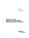
Front panel of the BayStack 150 hub .......................................................1-4
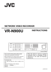
Front panel of the BayStack 151 hub .......................................................1-4
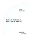
Front panel of the BayStack 152 hub .......................................................1-5
Front panel of the BayStack 153 hub .......................................................1-5
Rear panel of the BayStack 150 and 152 hubs .......................................1-8
Rear panel of the BayStack 151 and 153 hubs .......................................1-8
AUI port on the rear panel of the hub .......................................................1-9
Figure 3-1.
Figure 3-2.
Figure 3-3.
Installing the BayStack 150-series hubs in a rack ....................................3-3
A typical stack arrangement .....................................................................3-4
Installing the transceiver tray ...................................................................3-7
Figure 4-1.
Figure 4-2.
Figure 4-3.
Figure 4-4.
Figure 4-5.
Figure 4-6.
Diagnostic display ....................................................................................4-5
Boot Main Menu .......................................................................................4-6
Boot File Configuration Menu ..................................................................4-7
IP Configuration Menu .............................................................................4-8
BayStack NMM copyright screen .............................................................4-9
Main Menu .............................................................................................4-10
Figure 5-1.
Figure 5-2.
Figure 5-3.
Sample configuration menu .....................................................................5-2
Boot configuration menu hierarchy flowchart ...........................................5-4
Runtime configuration menu hierarchy flowchart .....................................5-8
Figure B-1.
Replacing the power supply .................................................................... B-2
Figure D-1.
Figure D-2.
Straight-through twisted pair cable ......................................................... D-2
Crossover twisted pair cable ................................................................... D-2
893-01021-A
xi
8931021.BK Page xii Thursday, August 14, 1997 12:08 PM
xii
893-01021-A
8931021.BK Page xiii Thursday, August 14, 1997 12:08 PM
Tables
Table 1-1.
Table 1-2.
Description of hub status LEDs ...............................................................1-6
Description of port status LEDs ...............................................................1-7
Table 3-1.
Selecting cables for connecting to other devices .....................................3-5
Table 4-1.
Management console configuration parameters ......................................4-4
Table 5-1.
Table 5-2.
Table 5-3.
Table 5-4.
Table 5-5.
Table 5-6.
Table 5-7.
Table 5-8.
Table 5-9.
Table 5-10.
Table 5-11.
Boot Main Menu commands ....................................................................5-5
Boot File Configuration Menu commands ................................................5-6
Protocol Configuration Menu commands .................................................5-7
Runtime Main Menu commands ..............................................................5-9
Runtime boot Configuration Menu commands .......................................5-10
Runtime Protocol Configuration Menu commands ................................5-11
Runtime IP Configuration Menu commands ..........................................5-12
Runtime boot File Configuration Menu commands ................................5-12
Runtime Profile Configuration Menu commands ...................................5-13
Runtime Port Selection Table Menu commands ....................................5-14
Runtime SNMP Configuration Menu commands ...................................5-15
Table D-1.
Table D-2.
Table D-3.
RJ-45 pin assignments ........................................................................... D-1
RJ-45 plug pin assignment for cascade cable ........................................ D-3
Communication port connection options ................................................. D-4
893-01021-A
xiii
8931021.BK Page xiv Thursday, August 14, 1997 12:08 PM
xiv
893-01021-A
8931021.BK Page xv Thursday, August 14, 1997 12:08 PM
Preface
Congratulations on your purchase of a BayStack™ 150-series hub. The BayStack
150-series hubs let you build a 10 megabit per second (Mb/s) Ethernet hub stack
with convenient setup, offering an unprecedented degree of flexibility, and turn
your network into the ideal connectivity solution by maximizing network
performance. The BayStack 150 and 152 hubs provide full Simple Network
Management Protocol (SNMP) manageability.
In this guide, the BayStack 150, 151, 152, and 153 Ethernet Hubs are referred to
collectively as the BayStack 150-series hubs.
Purpose
This guide provides information about using the features and capabilities of the
BayStack 150-series hubs, including using the interface to perform network
management operations from the BayStack 150 and 152 hubs.
Audience
This guide is intended for Ethernet local area network administrators with the
following background:
893-01021-A
•
Working knowledge of IBM PC terminology and operation
•
Working knowledge of DOS 5.0
•
Working knowledge of 10BASE-T operations
•
Familiarity with the IP or UNIX protocols
•
Bay Networks® network experience
xv
8931021.BK Page xvi Thursday, August 14, 1997 12:08 PM
Installation and Reference for the BayStack 150-series Ethernet Hubs
Conventions
This section describes the conventions used in this guide.
Special Message Formats
This guide uses the following formats to highlight special messages:
Note: This format is used to highlight information of importance or special
interest.
Caution: This format is used to highlight information that will help you prevent
equipment failure or loss of data.
Warning: This format is used to highlight material involving possibility of injury
or equipment damage.
Two-tiered Procedure Format
The procedural steps in this guide are presented in a two-tiered format. The first
tier describes the step very briefly but precisely. An experienced user may need to
read only the first tier to complete the task. The second tier describes the step in
more detail and includes results of performing the step.
Use of Enter, Type, and Press
This guide uses “enter,” “type,” and “press” to describe the following actions:
xvi
•
When you read “enter,” type the text and press the Enter key.
•
When you read “type,” type the text, but do not press the Enter key.
•
When you read “press,” press only the alphanumeric or named key.
893-01021-A
8931021.BK Page xvii Thursday, August 14, 1997 12:08 PM
Preface
Other Conventions
This guide uses the following typographical conventions:
italics
Book titles and UNIX file, command, and directory
names.
courier font
Screen text, user-typed command-line entries.
Initial Caps
Menu titles and window and button names.
[Enter]
Named keys in text are shown enclosed in square
brackets. The notation [Enter] is used for the Enter key
and the Return key.
[Ctrl]+C
Two or more keys that must be pressed simultaneously
are shown in text linked with a plus (+) sign.
Related Publication
For more information about using the BayStack 150-series hubs, refer to BayStack
150-series Ethernet Hubs Installation Instructions (Bay Networks part number
893-01028-A). Translated into five languages, this document provides installation
procedures for the BayStack 150-series hubs. Most of the information is presented
through illustrations.
Ordering Bay Networks Publications
To purchase additional copies of this document or other Bay Networks
publications, order by part number from Bay Networks Press™ at the following
numbers:
893-01021-A
•
Phone--U.S./Canada: 1-888-422-9773
•
Phone--International: 1-510-490-4752
•
Fax--U.S./Canada and International: 1-510-498-2609
xvii
8931021.BK Page xviii Thursday, August 14, 1997 12:08 PM
Installation and Reference for the BayStack 150-series Ethernet Hubs
Bay Networks Customer Service
You can purchase a support contract from your Bay Networks distributor or
authorized reseller, or directly from Bay Networks Services. For information
about, or to purchase a Bay Networks service contract, either call your local Bay
Networks field sales office or one of the following numbers:
Region
Telephone number
Fax number
United States and
Canada
1-800-2LANWAN; then enter Express
Routing Code (ERC) 290, when prompted,
to purchase or renew a service contract
1-508-670-8766
1-508-916-8880 (direct)
Europe
33-4-92-96-69-66
33-4-92-96-69-96
Asia/Pacific
61-2-9927-8888
61-2-9927-8899
Latin America
561-988-7661
561-988-7550
How to Get Help
If you purchased a service contract for your Bay Networks product from a
distributor or authorized reseller, contact the technical support staff for that
distributor or reseller for assistance.
If you purchased a Bay Networks service program, call one of the following Bay
Networks Technical Solutions Centers:
Technical Solutions Center
Telephone number
Fax number
Billerica, MA
1-800-2LANWAN
508-670-8765
Santa Clara, CA
1-800-2LANWAN
408-495-1188
Valbonne, France
33-4-92-96-69-68
33-4-92-96-69-98
Sydney, Australia
61-2-9927-8800
61-2-9927-8811
Tokyo, Japan
81-3-5402-0180
81-3-5402-0173
Use Express Routing Code 100 for support on Ethernet hub products.
xviii
893-01021-A
8931021.BK Page xix Thursday, August 14, 1997 12:08 PM
Preface
For More Information
For information about Bay Networks and its products, visit the Bay Networks
World Wide Web (WWW) site at http://www.baynetworks.com. To learn more
about Bay Networks Customer Service, select Customer Service on the opening
Web page.
893-01021-A
xix
8931021.BK Page xx Thursday, August 14, 1997 12:08 PM
8931021.BK Page 1 Thursday, August 14, 1997 12:08 PM
Chapter 1
Introduction
This chapter gives you an overview of the BayStack 150-series hubs, provides a
list of the features of the hubs, describes the front and rear panels of the hubs, and
explains in detail the components on each of the panels.
Overview
An overview of the BayStack 150-series hubs includes the following items:
•
Media connection flexibility
The hubs support multiple Ethernet media types, with 12 or 24 ports for
twisted pair cabling and one AUI port that provides connectivity for a variety
of Ethernet wiring environments, from basic workgroups to remote branch
offices. An appropriate external transceiver allows the AUI port to be used to
connect to any type of 10 Mb/s Ethernet medium.
•
Stackability and manageability
A stack of BayStack 150-series hubs can be separated up to 100 meters (m)
apart and still maintain their manageability. Up to eight hubs can be
connected together using unshielded twisted pair (UTP) or shielded twisted
pair (STP) cable. When daisy-chaining eight hubs, seven client hubs (the
BayStack 151 and 153 hubs) can be used to share the SNMP management
agent of the managed hub (BayStack 150 and 152 hubs) to provide a
connectivity solution for departmental Ethernet networks ranging up to 200
(192 twisted pair + 8 AUI) nodes. Bandwidth can be increased substantially
using microsegmentation and LAN switching technologies.
893-01021-A
1-1
8931021.BK Page 2 Thursday, August 14, 1997 12:08 PM
Installation and Reference for the BayStack 150-series Ethernet Hubs
•
Innovative display
The hubs are equipped with a large, clear display that shows an extensive
array of information at a glance, including link, receive, and partitioning
status; bandwidth utilization; collision ratio; and data transmission errors.
Runt occurrences, data packet corruption, management status, late collisions,
and connection to the communication port are shown on the BayStack 150
and 152 hubs.
•
Security
The hubs support intrusion control and eavesdrop protection, which prevents
unauthorized individuals from accessing the network. Through the network
management software, Ethernet addresses that represent authorized users can
be assigned to each hub port. If a packet is received from a port that contains a
source address from other than the authorized user, the port is disabled and a
notification is sent to the network manager.
Features
The BayStack 150-series hubs have the following features:
•
Compliance with the IEEE 802.3 standards
•
Sturdy metal enclosure
•
Independent RJ-45 ports for Category 3, 4, and 5 twisted pair wiring (either
UTP or STP) to nodes in a 10BASE-T-compliant network
— 12 RJ-45 ports on the BayStack 152 and 153 hubs
— 24 RJ-45 ports on the BayStack 150 and 151 hubs
•
A switchable uplink port that allows stacks of hubs to be daisychained
together easily to further expand the network
•
Hub stack cascade cabling that does the following:
— Allows a total distance of 100 meters (m) between the first hub and the
last hub in the daisy chain
— Expands network capacity up to 8 hubs in a single stack for a maximum
of 192 ports (and 8 AUI ports)
1-2
893-01021-A
8931021.BK Page 3 Thursday, August 14, 1997 12:08 PM
Introduction
•
A recessed AUI connector that does the following:
— Accommodates most standard Ethernet transceivers
— Allows the transceiver to be safely and conveniently tucked away
— Has a custom tray for easy insertion and removal of a recessed
transceiver or cable
•
A clear, easy-to-read front panel display that provides comprehensive
diagnostic indication of network status, allowing managers to diagnose and
troubleshoot instantly
•
SNMP-based management from the BayStack 150 and 152 hubs
•
Full configurability for either in-band or out-of-band signaling using any
SNMP-based network management system
•
A flash EPROM for software upgradability that is downloadable from a
Trivial File Transfer Protocol (TFTP) server
(A download request can be initiated from either Optivity or an out-of-band
console.)
•
Automatic bad port partition, collision detection, and jabber protection
•
A built-in removable power supply (replaceable without opening the
enclosure) that can be easily removed and replaced should damage occur
•
Automatic voltage selection (100 to 240 VAC, 50 to 60 Hz) without fuse
changes or manual voltage range settings
•
A slim one-unit profile, making the hub usable as a standalone desktop unit or
as a rack-mountable unit
•
Compliance with:
— FCC Class A
— CE Mark
— VCCI Level 1
•
Hub IDs automatically assigned during initialization or when daisy-chain
links are changed
•
An RS-232 communication port for out-of-band management.
Telnet network management is also supported. The RS-232 serial console
port can be configured as either local console or remote access through Telnet,
as well as updating to the latest firmware via TFTP.
893-01021-A
1-3
8931021.BK Page 4 Thursday, August 14, 1997 12:08 PM
Installation and Reference for the BayStack 150-series Ethernet Hubs
•
Redundant backup management
To maximize management uptime, two managed hubs can be put in the same
stack. If the first one goes down, the backup hub can automatically take over
to provide uninterrupted traffic monitoring and network control.
Physical Description
The following sections provide physical descriptions of the hubs and an overview
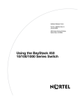
of the components on the front and rear panels. If you are using the BayStack 151
or 153 hub, your unit may not have some of the components. The unused
components are clearly indicated in the descriptions in this chapter.
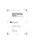
Front Panel
The front panel of the hub contains the RJ-45 10BASE-T Ethernet ports, the
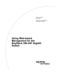
LEDs, and the MDI/MDI-X switch for port 1. Figure 1-1 and Figure 1-3,
respectively, illustrate the front panels of the BayStack 150 and 152 hubs, the
units that have built-in network management modules (NMMs). Figure 1-2 and
Figure 1-4, respectively, illustrate the front panels of the BayStack 151 and 153
hubs, the units that do not have built-in NMMs.
12
Master
Con
1
2
13
14
1
3
AUI
5
Runt
F/A
L/C
6
7
8
3
4
15
16
17
18
19
5
10
20
>40
1
Link/Rx
150 10BASE-T HUB
Disable
9
In
Out
10
11
12
22
23
34
Hub ID
20
10
21
1
2
3
4
5
6
13
14
15
16
17
18
7
8
9
10
11
12
19
20
21
22
23
24
1
MDI
Auto Part
5
Utilization %
Other Isolate
MDI-X
>20
Collision
7520EA
Figure 1-1.
Front panel of the BayStack 150 hub
1
12
1
2
3
13
14
15
1
3
5
AUI
CoL
4
5
6
Link/Rx
151 10BASE-T HUB
16
10
Utilization %
7
Disable
17
18
20
>40
19
8
9
Isolate
In
Out
10
11
12
22
23
34
21
2
3
4
5
6
13
14
15
16
17
18
8
9
10
11
12
19
20
21
22
23
24
1
MDI
Auto Part
20
Hub ID
MDI-X
7
7638EA
Figure 1-2.
1-4
Front panel of the BayStack 151 hub
893-01021-A
8931021.BK Page 5 Thursday, August 14, 1997 12:08 PM
Introduction
12
Master
Con
1
2
AUI
3
Link/Rx
152 10BASE-T HUB
4
Runt
5
F/A
L/C
Other Isolate
In
Hub ID
8
9
10
11
12
3
5
10
20
>40
Utilization %
1
5
10
2
3
4
5
6
13
14
15
16
17
18
1
MDI
Disable/Auto Part
7
1
1
Out
6
MDI-X
>20
Collision
7521EA
Figure 1-3.
Front panel of the BayStack 152 hub
12
1
2
3
Link/Rx
153 10BASE-T HUB
AUI
Col
4
5
Isolate
In
6
Hub ID
8
9
10
11
12
1
3
5
10
20
>40
2
3
4
5
6
13
14
15
16
17
18
1
MDI
Disable/Auto Part
7
1
Out
Utilization %
MDI-X
7639EA
Figure 1-4.
Front panel of the BayStack 153 hub
RJ-45 10BASE-T Ethernet Ports
The RJ-45 10BASE-T Ethernet ports are used for connecting the hub to network
devices using 10BASE-T shielded or unshielded twisted-pair cable. Each of the
Ethernet ports are MDI-X (normal) ports. The Ethernet ports connect to
workstations and servers using straight-through cables and to other hubs using
crossover cables.
MDI and MDI-X Switch
The MDI and MDI-X switch converts port 1 from an MDI-X (normal) port to an
MDI (uplink) port to allow you to connect the hub to an Ethernet switch or to
another hub using a straight-through cable.
LED Indicators
Each of the ports has an LED to indicate port status. The LEDs indicate link,
activity, and partitioning status. The port status indicators always come on when
the hub is powered on. In normal operation, after the POST (power-on self-test) is
completed, the LEDs turn off.
893-01021-A
1-5
8931021.BK Page 6 Thursday, August 14, 1997 12:08 PM
Installation and Reference for the BayStack 150-series Ethernet Hubs
Table 1-1 describes the LEDs that monitor the hub status.
Table 1-1.
Description of hub status LEDs
Label
Color
Activity
Description
Master
(BayStack 150 and
152 hubs only)
Green
On
The hub is serving as an active managed hub in the stack.
Con (BayStack 150
and 152 hubs only)
Green
On
The communications port is being used for the console
interface or out-of-band network management. The mode of
the console port is set using the console interface or an
SNMP-based network management system.
AUI
Green
Blinking
A transceiver is attached to the AUI port on the rear panel of
the hub, and data packets are being received through the AUI
port.
Yellow
On
The AUI port is partitioned.
Runt
(BayStack 150 and
152 hubs only)
Amber
On
The hub is receiving a packet that is too short. Ethernet
packets must be at least 64 bytes long. Runts are often a
normal side effect of collisions.
F/A
(BayStack 150 and
152 hubs only)
Amber
On
Data packets have been corrupted during transmission.
A frame check sequence (FCS) error occurs when a data
packet fails an internal consistency check. An alignment error
occurs when the bits in a packet do not add up to a whole
number of bytes.
L/C
(BayStack 150 and
152 hubs only)
Amber
On
A collision is detected that happened after the 512th bit of a
frame. Late collisions may be caused by overly long delays in
the Ethernet network, either because a cable is too long or
there are too many repeaters or hubs on the network.
Other
(BayStack 150 and
152 hubs only)
Amber
On
Other types of Ethernet errors are occurring.
Isolate
Amber
On
The hub has been manually segmented from the rest of the
network. Usually, the hubs are connected together into a
single Ethernet collision domain through the daisy-chain
connectors on the back. Segmenting a hub places the hub in
its own collision domain while allowing it to be managed with
the rest of the stack.
In
Green
On
Another hub is connected to the In cascade port on the back
of the hub.
Out
Green
On
Another hub is connected to the Out cascade port on the back
of the hub.
1-6
893-01021-A
8931021.BK Page 7 Thursday, August 14, 1997 12:08 PM
Introduction
Table 1-1.
Description of hub status LEDs (continued)
Label
Color
Activity
Description
Col (BayStack 151
and 153 hubs only)
Amber
Blinking
Collision is occurring on one of the ports. Collisions occur
when two or more devices on the network attempt to transmit
at the same time. Whenever there is a collision, all of the
devices involved back off and retransmit after a small delay.
Collisions are normal on an Ethernet network, but when
excessive collisions occur, the bandwidth of the network is
reduced. This response may indicate network overload or
some sort of hardware or wiring problem.
Collision/1,5,10, ≥20
(BayStack 151 and
153 hubs only)
Amber
On
Collision rate is measured in units of tens of collisions per
second.
Hub ID
Utilization %
The Unit ID of the hub is displayed. In a hub stack, each hub
unit should have a unique ID. The hub is capable of setting the
hub ID automatically, freeing you from having to do so. Using
the NMM, if you have the BayStack 150 or BayStack152 hub,
you can turn on Group ID flashing, which will make the hub ID
indicator flash off and on. This ID flashing may be useful for
identifying a specific hub or a hub stack within a large bank of
hubs.
Green
Blinking
The amount of data traffic is measured. When the data traffic
exceeds 40%, the last LED blinks amber.
Table 1-2 describes the LEDs that monitor each port.
Table 1-2.
Description of port status LEDs
Label
Color
Activity
Description
Link/Rx
Green
On
The port is connected to a port on an Ethernet device that is
powered on, and the connection between the ports is valid.
Off
The port is connected to a port on an Ethernet device that is
powered off.
The connection between the port on the hub and the port on the
connected device is not valid.
Blinking
The connected port is receiving data packets. Each data packet
will be transmitted through all other connected ports on the hub (or
all ports in the hub stack).
Disable
Yellow
On
The port has been manually partitioned.
Autopartition
Yellow
Blinking
The port has been automatically partitioned.
893-01021-A
1-7
8931021.BK Page 8 Thursday, August 14, 1997 12:08 PM
Installation and Reference for the BayStack 150-series Ethernet Hubs
Rear Panel
The rear panel of the BayStack 150-series hubs, as illustrated in Figure 1-5 and
Figure 1-6, contains the stackable cascade connectors, the AUI port, a receptacle
for the power cord, and an outlet for the removable power supply. As illustrated in
Figure 1-5, the BayStack 150 and 152 hubs also have a communications port.
Comm Port
Cascade
In
Out
AC LINE
100-240 VAC
50-60 Hz
1.5A MAX
7668EA
Figure 1-5.
Rear panel of the BayStack 150 and 152 hubs
Cascade
In
Out
AC LINE
100-240 VAC
50-60 Hz
1.5A MAX
7641EA
Figure 1-6.
Rear panel of the BayStack 151 and 153 hubs
Cascade Connectors
The stackable cascade connectors consist of two RJ-45 ports. They allow you to
connect the hubs together in a stack of up to 8 hubs and a maximum of 200 ports
(192 10BASE-T Ethernet ports plus 8 AUI connections).
Communications Port
The Communications Port (only on the BayStack 150 and 152 hubs) is used to
connect the managed hub to a network management station for out-of-band
management or for simple management using the communications port. The
communications port has a standard 9-pin RS-232 female connector.
1-8
893-01021-A
8931021.BK Page 9 Thursday, August 14, 1997 12:08 PM
Introduction
AUI Port
The AUI port is used for connecting the hub to a 10BASE5 thick Ethernet
backbone or to other types of Ethernet media. The recessed AUI port (see
Figure 1-7) accommodates most standard transceivers, also known as Media
Access Units (MAUs), allowing the transceiver to be safely and conveniently
tucked away.
Comm Port
Cascade
In
Out
AC LINE
100-240 VAC
50-60 Hz
1.5A MAX
AUI
7644EA
Figure 1-7.
AUI port on the rear panel of the hub
Removable Power Supply
The removable power supply can be purchased and changed in case of failure. The
power supply consists of an IEC receptacle, a fan, circuitry, and a connector to the
hub. For further information about power supply replacement, refer to
Appendix B, “Replacing the Power Supply.”
893-01021-A
1-9
8931021.BK Page 10 Thursday, August 14, 1997 12:08 PM
8931021.BK Page 1 Thursday, August 14, 1997 12:08 PM
Chapter 2
Planning the Network Configuration
This chapter provides information for planning your network and incorporating
the BayStack 150 and 152 hubs into your network.
Building Hub Stacks
You can combine up to eight hubs (BayStack 150 and 152 hubs or any other
combination of BayStack 150-series hubs) into a single manageable hub stack.
Building a hub stack has two advantages:
893-01021-A
•
All of the hubs can be managed as a single unit using a network management
system or the console interface. Up to 200 10BASE-T ports can be controlled
and monitored from a single management screen. Only one managed hub is
required, and less costly unmanaged hubs can be used for the rest of the stack.
•
The entire hub stack counts as a single repeater hub when planning your
network. The Ethernet standard requires that there be at most four repeaters
between any two stations on the network. Using the built-in daisy-chain ports
on the hub allows you to link eight hubs together without violating the
repeater count limitation.
2-1
8931021.BK Page 2 Thursday, August 14, 1997 12:08 PM
Installation and Reference for the BayStack 150-series Ethernet Hubs
Ethernet Rules
When planning your network, it is important to keep the following Ethernet
configuration rules in mind:
•
Make sure that there are no more than four repeaters (including hubs or hub
stacks) between any two stations on the network.
•
If you need to exceed the repeater limit, use a bridge or Ethernet switch to
divide the network into separate collision domains.
•
Make sure that none of the cable links exceed the maximum length for that
type of cable.
Hub Roles
The BayStack 150-series hubs support both managed (BayStack 150 and 152)
hubs and unmanaged (BayStack 151 and 153) hubs. In addition, more than one
managed hub can be placed in a single hub stack. Therefore, a hub in the stack can
take on different roles depending on the type of hub it is and its position in the hub
stack.
Position in the Stack
Hubs in the hub stack are connected using the two daisy-chain Cascade ports
located at the rear of the hub. The positions and roles of the hubs within the stack
are described in the following sections.
Managed Hub Roles
You can include more than one managed hub in a hub stack, allowing you to
continue to manage the hub stack, even if the management agent of one of the
managed hubs fails. The hub currently managing the stack is called the active
managed hub, and other managed hubs in the stack are called standby managed
hubs.
If a managed hub is at the head of the stack, it automatically becomes the active
managed hub. Otherwise, it will wait for management commands from another
managed hub upstream. If it receives commands from a managed hub, it becomes
a standby managed hub, controlled by the active managed hub. If it does not
receive any commands, or if the active managed hub fails, it will become the
active managed hub.
2-2
893-01021-A
8931021.BK Page 3 Thursday, August 14, 1997 12:08 PM
Planning the Network Configuration
If there are more than two managed hubs in the stack, the standby indicator of the
additional managed hubs will not light. However, if the active managed hub at the
head of the stack fails, the first standby managed hub will become the active
managed hub and the next managed hub will then become a standby managed
hub.
A managed hub can only manage hubs that are downstream from it. Therefore,
you should place the hub that you want to serve as the active managed hub at the
head of the stack. If you want to use standby managed hubs, you should place
them directly downstream of the active managed hub. Otherwise, you will not be
able to control or monitor any unmanaged hubs upstream of the managed hub.
Each managed hub has its own IP address. All managed hubs respond to SNMP
management commands, although only the active managed hub is capable of
controlling and monitoring other hubs. If the active managed hub fails, then you
will need to use the IP address of the new active managed hub to manage the other
hubs in the stack.
Unmanaged Hub Roles
An unmanaged hub can operate as a standalone hub or can be a managed hub
controlled by an upstream active managed hub.
If there are no managed hubs in the hub stack, or if the active managed hub in the
stack fails and there is no standby managed hub to take its place, the unmanaged
hubs will be standalone hubs. However, the hubs continue to communicate with
other hubs in the stack through the cascade cable connections. In a case where the
managed hub fails, you should turn power to the unmanaged hubs off and then on
again to insure that they are in a valid state before using them as standalone hubs.
Standalone hubs all have a hub ID of 0. When a hub is a standalone hub, all ports
will be enabled and all settings such as hub segmenting and intrusion security will
have no effect.
When there is a working active managed hub in the stack, then each unmanaged
hub in the stack will be a managed hub controlled by the active managed hub and
will have its own hub identification (ID).
893-01021-A
2-3
8931021.BK Page 4 Thursday, August 14, 1997 12:08 PM
Installation and Reference for the BayStack 150-series Ethernet Hubs
Hub ID Numbers
Hub ID numbers, displayed on the front of the hub, are determined automatically
by the managed hub. When the managed hub starts up, it begins to assign hub ID
numbers to the standby managed hub and all of the unmanaged hubs. The
managed hub remembers the hub ID associated with each hub in the stack; even if
a hub is removed, the other hubs will keep their original hub IDs. When you add a
new hub to the stack, the managed hub will assign it an unused hub ID.
Cascading Hubs into a Hub Stack
Hubs are daisy chained together using 4-pair, Category 5, twisted pair cabling
with RJ-45 plugs on each end. A cascade cable of 30 centimeters (cm) is included
with the hub. If you need to make a longer cable, refer to the pinout information
on page D-3 of Appendix D, “Cables and Connectors.” The total length of all the
cables, measured from the first hub in the stack to the last, must not exceed 100 m.
2-4
893-01021-A
8931021.BK Page 1 Thursday, August 14, 1997 12:08 PM
Chapter 3
Installation
This chapter provides information about and procedures for checking the package
contents, preparing the site, and installing and verifying the installation of the
BayStack 150-series hubs.
Package Contents
Unpack the contents of the package and verify them against the following list:
•
One of the following BayStack 150-series hubs
— BayStack 150 (24-port managed hub)
— BayStack 151 (24-port unmanaged hub)
— BayStack 152 (12-port managed hub)
— BayStack 153 (12-port unmanaged hub)
893-01021-A
•
Accessory kit to include cabling, transceiver tray, four self-adhesive rubber
feet for installing the hub on a flat surface, and brackets with screws for
mounting the hub in a rack
•
Appropriate power cord
•
This manual
•
BayStack 150-series Ethernet Hubs Installation Instructions
3-1
8931021.BK Page 2 Thursday, August 14, 1997 12:08 PM
Installation and Reference for the BayStack 150-series Ethernet Hubs
Operating Environment
Before you begin installing your hub, prepare the installation site. Make sure the
operating environment, as listed in Appendix A, “Technical Specifications,” meets
the physical requirements of the hub.
Power Specifications
The BayStack 150-series hubs feature an autoselecting 100 to 240 VAC,
50 to 60 Hz power supply unit that works in most countries around the world.
Before connecting the hub to power with the supplied power cord, make sure any
cord used has a CEE-22 standard V female connector on one end. Make sure the
power cord has a plug on the other end that is appropriate for the country where
you are using the hub.
Caution: Use only power cords with a grounding path. Without a proper
ground, a person touching the unit is in danger of receiving an electrical shock.
Lack of a grounding path to the unit may result in excessive conducted or
radiated emissions.
Installing the Hub on a Flat Surface
Making sure the bottom surface of the chassis is clean and dry, apply one of the
four self-adhesive rubber feet to each of the marked locations on the bottom of the
hub.
To install the hub, set the unit on a tabletop, shelf, or any other flat surface. Allow
at least 2 inches on each side for proper ventilation and 5 inches at the back for
power cord clearance.
3-2
893-01021-A
8931021.BK Page 3 Thursday, August 14, 1997 12:08 PM
Installation
Installing the Hub in a Rack
Confirm that the rack is an EIA-standard 19-inch rack. For rack mounting
convenience, a pair of mounting brackets is included with the BayStack 150-series
hubs. You need a #2 Phillips screwdriver for attaching the mounting brackets. As
illustrated in Figure 3-1, attach the mounting brackets with the machine screws
that are included with the rack mount kit, and then mount the hub in the rack.
7678FA
Figure 3-1.
Installing the BayStack 150-series hubs in a rack
Cascading Hubs
Hubs in the hub stack are connected using the Cascade ports located at the rear of
the hub. Each hub has an In port and an Out port. Hubs are daisy chained together
by connecting the Out port of one hub to the In port of the next hub in the chain. A
typical stack arrangement (with a BayStack 150 or 152 hub at the top of the stack)
is illustrated in Figure 3-2.
All hubs connected through the In port of a hub can be considered downstream of
the hub positioned higher in the stack, and all hubs connected through the Out port
of the hub can be considered downstream of the hub positioned higher in the
stack. If a hub does not have any upstream hubs, it is at the head of the stack.
893-01021-A
3-3
8931021.BK Page 4 Thursday, August 14, 1997 12:08 PM
Installation and Reference for the BayStack 150-series Ethernet Hubs
Comm Port
Cascade
In
Out
Cascade
In
Out
Cascade
In
Out
7640EA
Figure 3-2.
A typical stack arrangement
Network Connections
Once you have set up your hubs and connected them in a stack, you are ready to
connect network stations and to connect your hub to the rest of your Ethernet
network. This section tells how to connect your hub to workstations and to other
hubs and network components on your local area network.
Be sure to refer to “Ethernet Rules” on page 2-2 when planning your network
connections.
Connecting Stations to the Hub
The RJ-45 10BASE-T Ethernet ports on your hub are used for connecting the hub
directly to network devices using crossover or straight-through 10BASE-T
shielded or unshielded twisted-pair (STP or UTP) cables.
Port 1 on the BayStack 150-series hubs is an RJ-45 10BASE-T Ethernet port,
configurable by a sliding switch to either an MDI (uplink) port or an MDI-X
(normal) port. All of the other ports on the BayStack 150-series hubs are MDI-X
(normal) 10BASE-T Ethernet ports and are not configurable.
3-4
893-01021-A
8931021.BK Page 5 Thursday, August 14, 1997 12:08 PM
Installation
Refer to Table 3-1 for information on setting the configurable switches and using
crossover or straight-through twisted pair cables when connecting to other
devices. Refer to Chapter D, “Cables and Connectors,” for more information
about crossover and straight-through twisted pair cables.
Table 3-1.
Selecting cables for connecting to other devices
Port
Configuration
Connecting
device
Connecting
port
Twisted pair
cable
MDI (Uplink)
Switch or hub
MDI-X (Normal)
Straight-through
MDI-X (Normal)
Switch or hub
MDI-X (Normal)
Crossover
PC or server
MDI (Uplink)
Straight-through
Insert the RJ-45 plug at one end into the Ethernet 10BASE-T port on the front of
the hub and at the other end into the Ethernet 10BASE-T port on the connecting
device. When the hub and the connected device at the other end of the connection
are turned on and the cable is connected at both ends, the Link LED for the port
should light.
If the Link LED does not light, follow these steps:
1.
Make sure that the connectors are seated correctly at both ends of the
cable.
2.
Check the continuity of the wires in the cable, as well as the pin
assignments on the RJ-45 plug.
3.
Make sure the network station where the port is connected is plugged in
and powered on.
4.
Check that the right type of cable is connected to port 1 and that the
MDI/MDI-X switch is set correctly for that port.
Daisy Chaining Hub Stacks
If you have to expand your network beyond an 8-port stack or connect your hub to
other parts of your network, you can daisy chain it using several different network
media, including 10BASE-T twisted-pair cabling, 10BASE2 thin coaxial cabling,
10BASE5 thick coaxial cabling, and FOIRL or 10BASE-FL fiber optic cabling.
893-01021-A
3-5
8931021.BK Page 6 Thursday, August 14, 1997 12:08 PM
Installation and Reference for the BayStack 150-series Ethernet Hubs
Using Twisted Pair Cable for Cascading
You can connect hubs or hub stacks together using ordinary twisted pair cabling.
This is the simplest method, but the distance between hub stacks cannot exceed
100 m and two RJ-45 connector ports must be available on each of the first and
last hubs for the cascade connections.
Twisted pair cabling is usually used to connect repeater hubs to Ethernet switches.
There are two different ways of cascading hubs using 10BASE-T cabling. The
first way is to use a crossover cable, which connects the transmitter of one hub
to the receiver of the other hub. Refer to Table 3-1 on page 5 for information on
choosing cables.
Using the AUI Port for Cascading
On the rear panel of the BayStack 150-series hubs, there is an AUI connector
designed for connecting the hub to various types of Ethernet media such as thick
Ethernet coaxial cable (10BASE5), thin Ethernet coax (10BASE2), or fiber optic
cabling (10BASE-FL). The AUI connector is recessed, allowing most types of
transceivers, known as Media Access Units (MAUs), to be installed partially
recessed within the rear panel of the hub. To make inserting and removing the
transceiver easier, a transceiver tray has been included with the hub.
Note: Because measurements of MAUs from different manufacturers may vary,
all MAUs may not fit properly into the tray. The MAU can be used without the
transceiver tray by removing the door covering the AUI port and inserting the
MAU directly into the AUI connector until the connection is secure.
To install a transceiver using the tray, refer to Figure 3-3 and follow these steps:
1.
Place the transceiver in the tray with the slotted stubs on the male AUI
connector of the transceiver fitting into the slots on the front of the tray.
2.
Unscrew the door covering the AUI port.
3.
Slide the tray and transceiver into the slot until the connection is secure.
Most transceivers should fit easily within the slot. To accommodate a larger
transceiver, insert a standard AUI cable using the tray. In this case, the cable
serves as a short extension to allow the transceiver to be used externally to the
hub enclosure.
3-6
893-01021-A
8931021.BK Page 7 Thursday, August 14, 1997 12:08 PM
Installation
Service
Port
In
Casc
ade
Out
AUI
7642FA
Figure 3-3.
Installing the transceiver tray
Using Thin Coaxial Cable for Cascading
With the addition of a 10BASE2 transceiver connected to the AUI port at the rear
of the hub, you can cascade the hub to other hubs or stations using thin coaxial
cabling. This method of cascading hubs gives additional flexibility over using
twisted pair cable, because you can cascade up to thirty hubs on a single thin
coaxial cable segment. The entire coaxial segment may be up to 185 m long.
Each device on the thin coaxial segment needs to have a BNC port or to use a
10BASE2 transceiver. The cables should be connected to the BNC ports using
BNC T-connectors, and there should be 50-ohm terminating resistors on each end.
Make sure that you leave at least 0.5 m of coaxial cable between any two nodes on
the thin coaxial cable segment.
Using Thick Coaxial Cable for Cascading
Transceivers connected to the AUI port can be used for connecting thick coaxial
Ethernet (10BASE5) or fiber optic (FOIRL or 10BASE-FL) cabling to the hub.
A thick Ethernet trunk can be up to 500 m long (preferably a single piece of
cable), and should have 50-ohm terminating resistors at each end. The cable shield
should be grounded at one end. A 10BASE5 transceiver usually taps directly into
the coaxial cable; taps should be placed at 2.5 m intervals, and you can have a
maximum of 100 taps on a single cable segment. You can connect the transceiver
to the AUI port on a hub using an AUI cable up to 50 m long.
893-01021-A
3-7
8931021.BK Page 8 Thursday, August 14, 1997 12:08 PM
Installation and Reference for the BayStack 150-series Ethernet Hubs
Using Fiber Optic Cable for Cascading
Using a fiber optic transceiver, you can link to another hub or a hub stack up to
1000 m away using Fiber Optic Inter-Repeater Link (FOIRL), or up to 2000 m
away using 10BASE-FL. The fiber optic transceiver should be inserted into the
AUI port. Two fiber optic cables are required; the transmit line of each transceiver
should be connected to the receive connector of the other.
When connecting a transceiver to the hub, the signal quality error (SQE) test
function of the transceiver must be disabled.
Completing the Installation
To connect power on your hub and verify installation, follow these steps:
1.
Plug the female IEC connector of the power cable into the power
connector on the back of the hub.
2.
Insert the three-pronged plug on the power cord into a nonswitched,
grounded power outlet on a wall, a power strip, or a grounded extension
cord.
When the managed hub is powered on, it does a power-on self-test (POST) to
verify that all of its components are working properly. As the test is performed, the
test progress is displayed on your terminal console.
After you have completed all necessary installation steps, verify that the
installation was successful by checking hub LEDs, port connections, and
configuration guidelines.
3-8
893-01021-A
8931021.BK Page 9 Thursday, August 14, 1997 12:08 PM
Installation
Your stack of hubs should meet these criteria:
•
Cable connections are in place.
•
All hubs and modules are installed.
•
Power is connected to all hubs in the stack.
•
The hub and any installed modules have completed their diagnostic cycle.
Checking the Diagnostic Displays
When you connect power to a hub, it performs the following diagnostic cycle:
•
The LEDs on the managed hub in the stack and then the LEDs on the
unmanaged hubs in the stack flash in two sequences before returning to
normal operation as described in Table 1-1 and Table 1-2 in Chapter 1,
“Introduction.”
•
A boot verification message is displayed if a display terminal is connected to
the communications port of a hub. For more information about connecting to
the communications port, see “Connecting to the Communications Port” in
Chapter 4, “Initializing the Network Management Module,” and Chapter 5,
“Using the Configuration Menus.”
Troubleshooting
Use the diagnostic displays to help you identify the type of problem you have;
then check the following:
•
Verify that all hubs in the stack are powered on.
•
Verify that all hubs in the stack are operating within the stack and are
not isolated.
If any hub ID displays a 0, it is isolated. Check that the cascade cable
connections follow compliance, and check the software to see that the hub
has not been isolated through the management software.
•
Verify that each cable and port connection has the correct pin assignment
and there are no loose connections.
A good link on a port is verified by the lit LED for that port.
893-01021-A
3-9
8931021.BK Page 10 Thursday, August 14, 1997 12:08 PM
Installation and Reference for the BayStack 150-series Ethernet Hubs
3-10
•
Verify that all media adapters and expansion slot modules are correctly
installed.
•
Verify that your NMM is functioning correctly. For further information
about the NMM, refer to Chapter 4, “Initializing the Network Management
Module.”
•
Verify that your installation complies with all BayStack and Ethernet
guidelines in Chapter 2, “Planning the Network Configuration.”
•
Use Optivity or other network management software to monitor the network
and to verify that the hub and modules are operating correctly. To do this,
refer to the documentation included with your network management software.
893-01021-A
8931021.BK Page 1 Thursday, August 14, 1997 12:08 PM
Chapter 4
Initializing the
Network Management Module
This chapter describes how to initialize the built-in network management modules
(NMMs) for the BayStack 150 and 152 hubs.
Only after the NMM has been initialized is it possible to manage your BayStack
150-series hubs or stack of hubs. For further information about using the menus
after your NMM has been initialized, refer to Chapter 5, “Using the Configuration
Menus.”
Only after the NMM has been initialized is it possible to use the Telnet Protocol to
remotely access and manage your hub or stack. For further information about
using Telnet, refer to “Using the Telnet Protocol to Access the Configuration
Menu,” on page 4-10 of this chapter.
Understanding the NMM Booting and Initializing Process
For an NMM to start itself (boot) properly, you first have to initialize it; that is,
you must provide it with the information it needs to find and communicate with
the network management software. This section gives an overview of the boot
process and general initialization requirements.
After power is connected to the hub, the NMM starts its four-stage boot process.
•
893-01021-A
In the first stage, the NMM runs self-test diagnostics. Diagnostic messages are
displayed on your monitor if you have a terminal connected to the Comm
(communications) port (see Figure 1-5 on page 1-8). If no errors are detected,
the NMM continues to the second stage.
4-1
8931021.BK Page 2 Thursday, August 14, 1997 12:08 PM
Installation and Reference for the BayStack 150-series Ethernet Hubs
•
In the second stage, the NMM sends out a Bootstrap Protocol (BootP) request
for the IP address of the server. The NMM boot mode parameter determines
whether the NMM should look for this address locally in electrically erasable
programmable read-only memory (EEPROM) or from a file stored remotely
on a server (network using BootP). The NMM needs its address to identify
itself to the network management software. Once the NMM receives its
address, it continues to the third stage.
•
In the third stage, the NMM requests configuration data. The config load
mode parameter determines whether the NMM should look for this data
locally (Local) or from a file stored remotely on a server (Remote, Remote w/
Local Backup). The configuration data tells the NMM how to interact
with the network and other network devices. Once the NMM reads the
configuration data, it continues to the final stage of the boot process.
•
In the fourth and final stage, the NMM requests an agent image. The image
load mode parameter (Local, Remote, Remote w/Local Backup) determines
whether a local or remote agent image is used. The configuration file can be
used to specify the path name and file name of the agent image. The agent
image program allows the NMM to monitor network activity, respond to
SNMP requests, and collect network performance statistics.
After completing the boot process, the NMM starts actively monitoring your
network.
Initializing the NMM to Boot Remotely
An NMM can receive all of its boot information remotely through a BootP/load
server. The benefit of having one remote location for downloading boot
information to all the NMMs in your network is that you can configure and
download new files to all NMMs from a single convenient location. Downloading
files from a single location eliminates the need for individual configuration of
each NMM.
4-2
893-01021-A
8931021.BK Page 3 Thursday, August 14, 1997 12:08 PM
Initializing the Network Management Module
Setting up the BootP/load Server
The configuration and image files must be on your server if you want the NMM to
get those files from a BootP/load server on your network.
Note: For instructions on where to store the configuration and image files and
how to make them available on your BootP/load server or network management
station, refer to the documentation included with those products. In general, you
must copy the files to a specified directory and modify the configuration file.
The NMM gets the server IP address and the path and file name for the NMM
configuration file from the /etc/bootptab.txt file. The NMM configuration file, in
turn, can specify the path name and the file name of the image file. The NMM
sends a request to the server to read the NMM configuration file using TFTP and
then requests the server to transfer the image file using TFTP.
Note: Configuration and image files are available from the Bay Networks
home page on the World Wide Web (http://support.baynetworks.com/software/
Ethernet) or through an FTP
server at 134.177.3.26 (/ftp/pub/Agents).
You can change the file names of your configuration and image files as needed for
use in your own network. You may also need to modify other files on your server
to allow the NMM to boot from your network. For more information about
changing your configuration file, refer to Appendix C, “Boot Configuration File.”
893-01021-A
4-3
8931021.BK Page 4 Thursday, August 14, 1997 12:08 PM
Installation and Reference for the BayStack 150-series Ethernet Hubs
Connecting to the Communications Port
You use the RS-232 port (Comm Port) on the rear panel of the BayStack 150 and
152 hubs to initialize your NMM for booting locally, for booting remotely through
a BootP/load server, or for a modem connection using Telnet. You can also use the
Comm Port to verify boot diagnostics as the NMM runs automated self-tests and
attaches to the segment.
If you are connecting a terminal or PC to the console port, refer to instructions in
your equipment documentation to configure the terminal or PC to the parameters
in Table 4-1.
Table 4-1.
Management console configuration parameters
Parameter
Value
Baud rate
9600
Data bits
8
Stop bits
1
Parity
None
To connect a terminal or PC to the BayStack 150 or 152 hub to start the boot
process and initialize the built-in NMM, follow these steps:
4-4
1.
Connect the DB-9 plug at the end of the straight-through cable to the
console port on the rear panel of the hub.
2.
Connect the other end of the cable into the appropriate port on the
terminal or PC.
3.
Turn on power to the hub by connecting the power cord first to the power
receptacle on the rear panel of the hub and then to the wall outlet.
893-01021-A
8931021.BK Page 5 Thursday, August 14, 1997 12:08 PM
Initializing the Network Management Module
Starting the Booting Process and Initializing the NMM
When you turn on power to the hub, the boot process begins. Then after a
valid connection has been established, diagnostic messages similar to those in
Figure 4-1 are displayed.
Bay Stack 150 NMM POWER-ON SELF DIAGNOSTIC
------------------------------------------------------PROM Checksum Test
..... PASSED
.. PROM Checksum = 0X8AAA
DRAM
( 01024 KByte )
..... PASSED
LED Display Test
..... PASSED
E2PROM Integration Checksum
..... PASSED
29F040
..... PASSED
512 Kbytes Flash Memory Installed
Network Monitor SRAM Test
..... PASSED
DL-P2517B NIC Test
..... PASSED
Expansion Module Test
.....PASSED
Stack 150 SYSTEM CONFIG AND RUN TIME IMAGE DOWNLOAD
-------------------------------------------------------> DUPLICATED IP CHECKING: (Hit CTRL-C to stop system boot/
load )
.. IP Address:
0.0.0.0
.. Subnet Mask: 0.0.0.0
ARP Req Send
-----------3
Figure 4-1.
ARP Reply
ARP Retry
----------- ----------0
2
Time (Sec)
---------2
Diagnostic display
To initialize the NMM, follow these steps:
1.
893-01021-A
Press [Ctrl]+C to display the boot Main Menu, as illustrated in
Figure 4-2.
4-5
8931021.BK Page 6 Thursday, August 14, 1997 12:08 PM
Installation and Reference for the BayStack 150-series Ethernet Hubs
Boot Main Menu
Unit: 1
BayStack150 Ethernet NMM
Network Interface :
MAC Address
000081AAAAAB
Segment
1
Boot Mode
Boot Protocol
Management Protocol
local
IP
IP
Image Load Mode
Config Load Mode
Image Save Mode
m - Toggle boot mode
|
p - Toggle boot protocol
|
t - Toggle management protocol
|
i - Toggle image load mode
|
f - Toggle config file load mode
|
d - Toggle image save mode
|
k - Reset EEPROM to factory defaults |
[Esc] - Refresh boot main menu
|
c
b
j
e
g
w
z
-
local
local
noAvail
System configuration menu
Boot file configuration menu
IP configuration menu
Load and execute boot file
Perform power-up bootload sequence
Write boot config to EEPROM
Reset management module
Enter command:
Figure 4-2.
4-6
Boot Main Menu
2.
Press i to toggle the Image Load Mode selection to Network.
3.
Press f to toggle the Config File Load Mode selection to Network.
4.
Press b to display the Boot File Configuration Menu, as illustrated in
Figure 4-3.
893-01021-A
8931021.BK Page 7 Thursday, August 14, 1997 12:08 PM
Initializing the Network Management Module
Boot File Configuration Menu
Unit: 1
BayStack150 Ethernet NMM
NI Configuration and Image Files
Boot Server: 0.0.0.0
Boot Router: 0.0.0.0
Config File: [None]
Image File: [None]
a - Set configuration file
e - Set image file
[Esc] - Return to previous menu
|
|
r - Set boot router address
s - Set server address
Enter command:
Figure 4-3.
5.
Boot File Configuration Menu
Press a to select Set configuration file.
Enter the path where the configuration file is stored and the name of the
configuration file (for example, eftpboot/6150.100.cfg).
6.
Press e to select Set image file.
Enter the path where the image file is stored and the name of the image file
(for example, /eftpboot/6150.100.img).
7.
Press r to select Set boot router address.
Enter the IP address of the boot router (for example, 10.10.3.1).
8.
Press s to select Set server address.
Enter the address of the server where the image and configuration files are
stored (for example, 10.10.3.200).
9.
Press [Esc] to return to the Boot Main Menu, as illustrated in Figure 4-2.
10. Press j to display the IP Configuration Menu, as illustrated in Figure 4-4.
893-01021-A
4-7
8931021.BK Page 8 Thursday, August 14, 1997 12:08 PM
Installation and Reference for the BayStack 150-series Ethernet Hubs
IP Configuration Menu
Unit: 1
NI
IP Address
0.0.0.0
1:
BayStack150 Ethernet NMM
Subnet Mask
0.0.0.0
Default Gateway: 0.0.0.0
i - Set
s - Set
g - Set
[Esc] -
IP address
subnet mask
default gateway
Return to previous Menu
Enter command:
Figure 4-4.
IP Configuration Menu
11. Press i to select Set IP address.
Enter the IP address of the hub (for example, 10.10.3.50).
12. Press s to select Set subnet mask.
Enter the subnet mask number (for example, 255.255.255.0) if necessary for
your network. If not applicable, skip to step 13.
13. Press g to select Set default gateway.
Enter the IP address for your default gateway (for example, 10.10.3.1) if
necessary for your network. If not applicable, skip to step 14.
14. Press [Esc] to return to the Boot Main Menu, as illustrated in Figure 4-2.
15. Press w to select Write boot config to EEPROM.
All the parameters that you set for booting are written to the EEPROM in the
NMM of your BayStack 150 or BayStack 152 hub.
4-8
893-01021-A
8931021.BK Page 9 Thursday, August 14, 1997 12:08 PM
Initializing the Network Management Module
16. Press e or z to execute the boot file.
Select e to load and execute the boot file.
Select z to reset the network management module.
The booting process begins. The diagnostics are displayed (as illustrated in
Figure 4-1 on page 4-5), the image and configuration files are retrieved from
the server or workstation and loaded onto the NMM, and the BayStack NMM
copyright screen (as illustrated in Figure 4-5) is displayed.
The NMM is now ready to monitor your network devices.
* * * * * * * * * * * * * * * * * * * * * * * *
* Copyright (c) 1997
*
* Bay Networks, Inc.
*
* All Rights Reserved
* BayStack150 Ethernet NMM
*
Version v1.x.x.x *
* * * * * * * * * * * * * * * * * * * * * * * *
Press [Ctrl]+Y to begin
Figure 4-5.
BayStack NMM copyright screen
Note: This copyright screen appears after every power-up sequence or
reset.
17. Press [Ctrl]+Y to display the runtime Main Menu, as illustrated in
Figure 4-6.
This menu is referred to as the runtime Main Menu because parameters can be
set during runtime. Boot menus are menus that are displayed to enable you to
set parameters for the boot process when initializing your NMM. For more
information about setting parameters from both boot and runtime menus, refer
to Chapter 5, “Using the Configuration Menus.”
893-01021-A
4-9
8931021.BK Page 10 Thursday, August 14, 1997 12:08 PM
Installation and Reference for the BayStack 150-series Ethernet Hubs
Main Menu
Unit: 1
BayStack150 Ethernet NMM
MAC Address
Segment
Network Interface: 0040052997AE 1
b
f
j
d
p
o
-
Boot configuration menu
System configuration menu
Protocol configuration menu
Boot file configuration menu
Profile configuration menu
Port selection menu
|
|
|
|
|
|
n
k
w
z
r
e
-
SNM configuration menu
Reset EEPROM to factory defaults
Save values to EEPROM
Reset management module
Restart management module
Exit this session
Enter command:exit
Figure 4-6.
Main Menu
Using the Telnet Protocol to Access the Configuration Menu
After the built-in NMM in your BayStack 150 or BayStack 152 hub has been
initialized, you can use the Telnet Protocol for managing your hub or stack of
hubs remotely. To manage hubs remotely using a Telnet application, follow these
steps:
1.
Enter the IP address of the active managed hub you want to access.
The copyright screen is displayed, as illustrated in Figure 4-5.
2.
Press [Ctrl]+Y to display the Main Menu, as illustrated in Figure 4-6.
For information about setting parameters from the menus, refer to Chapter 5,
“Using the Configuration Menus.”
4-10
893-01021-A
8931021.BK Page 1 Thursday, August 14, 1997 12:08 PM
Chapter 5
Using the Configuration Menus
This chapter provides information about the boot and runtime menus of the
BayStack 150 and 152 hubs.
Accessing the NMM Configuration Menus
To modify the configuration parameters of a BayStack NMM through the
communications port, use a terminal connected to the communications port to
access the two series of configuration menus.
•
The boot configuration menus allow you to set the primary boot configuration
and initialize the NMM; that is, they tell the NMM how to identify itself to the
network management software and where to look for its configuration and
image information. These menus are available only before the image code is
loaded and the NMM is initialized. To access the Boot Main Menu (see
Figure 4-2 on page 4-6), press [Ctrl]+C from the Diagnostic display (see
Figure 4-1 on page 4-5). Refer to Chapter 4, “Initializing the Network
Management Module,” for further instructions on initializing.
•
The runtime configuration menus allow you to change the NMM operating
parameters while the NMM is running. You can access these menus only after
the NMM is operating.
To access the runtime Main Menu, press [Ctrl]+Y from the NMM copyright
screen (see Figure 4-5 on page 4-9).
893-01021-A
5-1
8931021.BK Page 2 Thursday, August 14, 1997 12:08 PM
Installation and Reference for the BayStack 150-series Ethernet Hubs
About the Configuration Menus
BayStack NMM configuration menus have a format similar to the sample shown
in Figure 5-1.
Menu identification
SNMP Configuration Menu
Product name
Slot: 1
Module
information
displays
SNMP read community: public
SNMP read-write community: private
SNMP authentication traps: Enabled
Error and status
message area
Commands
Command
entry line
r - Set SNMP read community string
w - Set SNMP read-write community string
t - Trap receivers menu
e - Toggle authentication trap
[Esc] - Return to previous menu
Enter command:
3609.2
Figure 5-1.
Sample configuration menu
The screen layout is based on common 80-character by 24-line ASCII terminal
display characteristics. Menu information is divided into the following five parts:
5-2
•
Menu identification (menu title)
•
Module information displays
•
Error and status messages
•
Commands
•
Command entry line
893-01021-A
8931021.BK Page 3 Thursday, August 14, 1997 12:08 PM
Using the Configuration Menus
Reading Module Information Displays
Some menus contain display fields that show current configuration parameter
values. In some cases, the display fields show read-only parameter values that are
set through hardware jumpers or switches. In other cases, the display fields show
parameter values that are set through commands initiated in that menu.
Reading Error and Status Messages
The configuration program displays error and status messages in the area between
the module information displays and the commands.
Executing Commands
Some commands switch between two or more settings; these commands “toggle”
a condition. Other commands are used to enter command information; these
commands set, add, or delete a parameter value. Still other commands initiate a
direct action.
To use menu commands, follow these steps:
1.
Enter the letter for the command you want to issue.
Some commands display another menu with its own commands. From one of
these menus, you again enter the letter for the command you want to issue.
When you enter a command that sets or changes a parameter value, a
submenu is displayed or a prompt and a text-entry field are displayed at the
bottom of the menu. When a command displays a text-entry field, enter the
requested information and press [Enter].
When you enter a toggle command, that parameter value changes in the
display portion of the menu. For example, when the SNMP Configuration
Menu (shown in Figure 5-1) displays:
SNMP authentication trap: Enabled
Entering the e command [Toggle authentication trap] changes the display to
read:
SNMP authentication trap: Disabled
2.
893-01021-A
Repeat step 1 if you want to change other parameters.
5-3
8931021.BK Page 4 Thursday, August 14, 1997 12:08 PM
Installation and Reference for the BayStack 150-series Ethernet Hubs
3.
Press [Esc] to return to the main menu when you have finished in that
submenu, if you are working from a submenu.
If you are working from a main menu, choose an appropriate command from
the command list.
Caution: Choosing the option to reset your hub results in the NMM saving
the factory default configuration and could cause an interruption of network
activity and require reconfiguration of the NMM configuration parameters.
Boot Configuration Menus and Commands
The commands found in the boot configuration menus primarily deal with how the
NMM boots (from the network or from EEPROM), the protocol the NMM uses in
the boot process (IP), the names and locations of the configuration and image
files, and the directions for downloading the correct configuration and image
information.
The boot configuration menus consist of a Main Menu and three submenus, as
shown in Figure 5-2.
Ctrl
+
C
Boot Main Selection Menu
m - Toggle boot mode
p - Toggle boot protocol
t - Toggle management protocol
i - Toggle image load mode
f - Toggle config file load mode sequence
d - Toggle image save mode
k - Reset EEPROM to factory defaults
[ESC] - Refresh boot main menu
c - System configuration menu
b - Boot file configuration
j - IP configuration menu
e - Load and execute boot file
g - Perform power-up boot load
w - Write boot config to EEPROM
z - Reset management module
Read-only displays
[Esc] Return to previous menu
a - Set configuration file
e - Set image file
r - Set boot router address
s - Set server address
[Esc] Return to previous menu
i - Set IP address
s - Set subnet mask
g - Set default gateway
[Esc] Return to previous menu
7682EA
Figure 5-2.
5-4
Boot configuration menu hierarchy flowchart
893-01021-A
8931021.BK Page 5 Thursday, August 14, 1997 12:08 PM
Using the Configuration Menus
Boot Main Menu
When you press [Ctrl]+C from the system diagnostic display, the boot Main Menu
(as illustrated in Figure 4-2 on page 4-6) is displayed. Select from the commands
shown in Table 5-1.
Caution: When using the commands from the boot Main Menu, always save any
values to EEPROM after making changes by pressing w. By not saving your
changes and pressing e, g, or z, you lose the values that you have entered.
Table 5-1.
893-01021-A
Boot Main Menu commands
Command
Function
m
[Toggle boot mode] Use this command to switch boot mode between
net (network) and local. The default is net.
p
[Toggle boot protocol] Use this command to display the boot
protocol. Because IP is the only protocol that is used, you cannot
toggle your selection.
t
[Toggle management protocol] Use this command to display the
management protocol. Because IP is the only protocol that is used,
you cannot toggle your selection.
i
[Toggle image load mode] Use this command to switch image load
mode between net (network) and local.
f
[Toggle config load mode sequence] Use this command to switch
the configuration load mode between net (network) and local.
d
[Toggle image save mode] Use this command to toggle image save
mode. The options are writeIfDiff, writeIfNewer, and noWrite.
k
[Reset EEPROM to factory defaults] Use this command to reset the
EEPROM contents to the factory default settings.
[Esc]
[Refresh boot main menu] Use this command to refresh the Boot
Main Menu screen.
c
[System configuration menu] Use this command to access the
System Configuration Menu. You can view system hardware
configuration information in this menu.
b
[Boot file configuration menu] Use this command to access the
Boot File Configuration Menu.
j
[IP configuration menu] Use this command to display the IP
Configuration Menu. You can set the IP address of the NMM, subnet
mask, and default gateway.
5-5
8931021.BK Page 6 Thursday, August 14, 1997 12:08 PM
Installation and Reference for the BayStack 150-series Ethernet Hubs
Table 5-1.
Boot Main Menu commands (continued)
Command
Function
e
[Load and execute boot file] Use this command to load and start the
boot process.
g
[Perform power-up bootload] Use this command to perform a full
BootP/TFTP boot load sequence.
w
[Write boot config to EEPROM] Use this command to save all newly
set parameter values to EEPROM. The NMM uses these new values
during its next boot load cycle.
z
[Reset management module] Use this command to reset the NMM
and start the self-test and loading process. This command prompts
you to verify the reset.
Boot System Configuration Menu
When you press c from the boot Main Menu, the boot System Configuration
Menu is displayed. This menu is a read-only display. The only command item is
[Esc] to return to the previous menu.
The boot System Configuration Menu includes the following information display:
•
Revision codes for the NMM printed circuit board
•
Memory configurations and processor type
•
Status of RAM tests
Boot File Configuration Menu
When you press b from the Boot Main Menu, the Boot File Configuration Menu is
displayed. Select from the commands in Table 5-2.
Table 5-2.
5-6
Boot File Configuration Menu commands
Command
Function
a
[Set configuration file] Use this command to select the name
of the configuration file. This command prompts you to enter the
path name and file name of the configuration file.
e
[Set image file] Use this command to select the name of the
image file. This command prompts you to enter the path name
and file name of the image file.
893-01021-A
8931021.BK Page 7 Thursday, August 14, 1997 12:08 PM
Using the Configuration Menus
Table 5-2.
Boot File Configuration Menu commands (continued)
Command
Function
r
[Set boot router address] Use this command to set the IP
address of the boot router.
s
[Set server address] Use this command to set the address of
the server where the image and configuration files are stored.
[Esc]
[Return to previous menu] Press [Esc] to return to the Main
Menu.
Boot IP Configuration Menu
When you press j from the Boot Main Menu, the boot IP Configuration Menu is
displayed. Select from the commands shown in Table 5-3.
Table 5-3.
Protocol Configuration Menu commands
Command
Function
i
[Set IP address] Use this command to set the IP address for the
NMM. This command prompts you to enter the IP address for the
NMM in dotted-decimal notation.
s
[Set subnet mask] Use this command to set the IP address that
serves as the subnet mask. This command prompts you to
specify the subnet mask IP address in dotted-decimal notation.
g
[Set default gateway] Use this command to set the default
gateway.
[Esc]
[Return to previous menu] Use this command to return to the
Boot Main Menu.
Runtime Configuration Menus and Commands
The runtime configuration menus provide a way to change operating values while
the NMM is running. You can access this set of menus only after the image code is
loaded. Press [Ctrl]+Y from the copyright screen (shown in Figure 4-5 on
page 4-9).
The runtime configuration menus consist of a Main Menu and seven submenus, as
shown in Figure 5-3.
893-01021-A
5-7
8931021.BK Page 8 Thursday, August 14, 1997 12:08 PM
Installation and Reference for the BayStack 150-series Ethernet Hubs
Ctrl
Main Selection Menu
b - Boot configuration menu
f - System configuration menu
j - Protocol Configuration Menu
d - Boot file configuration menu
p - Profile configuration menu
o - Port selection menu
n - SNMP configuration menu
k - Reset EEPROM to factory defaults
w - Save values to EEPROM
r - Reset management module
z - Restart management module
e - Exit this session
+
Y
Toggle boot mode
Toggle image load mode
Toggle image save mode
Toggle config load mode
[Esc] Return to previous menu
Read-only displays
[Esc] Return to previous menu
i - Set IP parameters
[Esc] Return to previous menu
i - Set IP address
s - Set subnet mask
g - Set default gateway
[Esc] Return to previous menu
a - Set configuration file
e - Set image file
r - Set boot router address
s - Set server address
[Esc] Return to previous menu
n - Set system name
i - Set system location
c - Set system contact
[Esc] Return to previous menu
r - Set SNMP read community string
w - Set SNMP read/write community string
e - Toggle authentication traps
[Esc] Return to previous menu
d - Display Port Status
p - Partition Port
u - Unpartition Port
[Esc] Return to previous menu
7681EA
Figure 5-3.
Runtime configuration menu hierarchy flowchart
Note: Changes to runtime commands require that you press the w command to
save configuration changes to EEPROM. Pressing r to reset the management
module or pressing z to restart the management module prevents the changes
being written to EEPROM.
5-8
893-01021-A
8931021.BK Page 9 Thursday, August 14, 1997 12:08 PM
Using the Configuration Menus
Runtime Main Menu
The commands listed in Table 5-4 can be selected from the runtime Main Menu.
Table 5-4.
893-01021-A
Runtime Main Menu commands
Command
Function
b
[Boot configuration menu] Use this command to display the Boot
Configuration Menu. You can toggle the boot mode, the image and config
file load modes, and the image save modes from this menu (see “Runtime
Boot Configuration Menu” later in this chapter).
f
[System configuration menu] Use this command to display the System
Configuration Menu. You can view system hardware configuration
information in this menu (see “Runtime System Configuration Menu” later
in this chapter).
j
[Protocol configuration menu] Use this command to display the
Protocol Configuration Menu. You can set or modify the IP parameters
from this menu (see “Runtime Protocol Configuration Menu” later in this
chapter).
d
[Boot file configuration menu] Use this command to display the Boot
File Configuration Menu. You can set or modify the image and
configuration tables for the NMM, including the address of the boot server
and the address of the boot router in this menu (see “Runtime Boot File
Configuration Menu” later in this chapter).
p
[Profile configuration menu] Use this command to display the Profile
Configuration Menu. You can enter descriptions for the system name,
system location, and system contact in this menu (see “Runtime Profile
Configuration Menu” later in this chapter).
o
[Port selection menu] Use this command to display the Port Selection
Table Menu. You can display the port status and partition or unpartition the
ports for a specified hub (see “Runtime Port Selection Table Menu” later in
this chapter).
n
[SNMP configuration menu] Use this command to display the SNMP
Configuration Menu. You can set or modify the SNMP parameters for the
NMM in this menu (see “Runtime SNMP Configuration Menu” later in this
chapter).
k
[Reset EEPROM to factory defaults] Use this command to reset the
EEPROM contents to the factory default settings. This command prompts
you to verify the reset request.
w
[Save values to EEPROM] Use this command to save any changed
parameter values to EEPROM. When you enter this command, an
informational message confirming the save is displayed.
5-9
8931021.BK Page 10 Thursday, August 14, 1997 12:08 PM
Installation and Reference for the BayStack 150-series Ethernet Hubs
Table 5-4.
Runtime Main Menu commands (continued)
Command
Function
z
[Reset management module] Use this command to reset the NMM. This
command initiates the NMM self-test and hardware reset process. This
command prompts you to confirm the reset.
r
[Restart management module] Use this message to restart the NMM.
This command causes the NMM to load and execute the agent code
stored in NMM memory. This command prompts you to confirm the restart.
e
[Exit this session] Use this command to exit the menus and return to the
copyright screen.
Runtime Boot Configuration Menu
When you press b from the runtime Main Menu, the Boot Configuration Menu is
displayed. This menu displays the current values and next boot values for the boot
mode, image load mode, image save mode, and configuration load mode for the
NMM. You can select from the commands shown in Table 5-5.
Table 5-5.
5-10
Runtime boot Configuration Menu commands
Command
Function
m
[Toggle boot mode] Use this command to switch the boot mode between
net (network) and local. The default is net.
i
[Toggle image load mode] Use this command to switch image load mode
between local, net (network), and locAsBk. The default is locAsBk.
s
[Toggle image save mode] Use this command to switch the image save
mode between noWrite, writeIfNewer, and writeIfDiff. The default is
writeIfDiff.
c
[Toggle config load mode] Use this command to switch configuration
load mode between local, net (network), and locAsBk. The default is
locAsBk.
[Esc]
[Return to previous menu] Use this command to return to the runtime
Main Menu.
893-01021-A
8931021.BK Page 11 Thursday, August 14, 1997 12:08 PM
Using the Configuration Menus
Runtime System Configuration Menu
When you press f from the runtime Main Menu, the System Configuration Menu
is displayed. This is a display screen only. Choosing escape returns you to the
previous menu.
Runtime Protocol Configuration Menu
When you press j from the runtime Main Menu, the Protocol Configuration Menu
is displayed. The menu displays the current values and next boot values for the
management protocol, default gateway (router), and frame type for the NMM. You
can select from the commands shown in Table 5-6.
Table 5-6.
893-01021-A
Runtime Protocol Configuration Menu commands
Command
Function
i
[IP configuration menu] Use this command to display the IP
Configuration Menu. Use this command to set the IP address, subnet
mask, and default gateway (router) (see “Runtime IP Configuration Menu”
next in this chapter).
[Esc]
[Return to previous menu] Use this command to return to the runtime
Main Menu.
5-11
8931021.BK Page 12 Thursday, August 14, 1997 12:08 PM
Installation and Reference for the BayStack 150-series Ethernet Hubs
Runtime IP Configuration Menu
When you press i from the runtime Protocol Configuration Menu, the IP
Configuration Menu is displayed. Select from the commands shown in Table 5-7.
Table 5-7.
Runtime IP Configuration Menu commands
Command
Function
i
[Set IP address] Use this command to set the IP address for the NMM.
This command prompts you to specify the IP address using
dotted-decimal notation.
s
[Set subnet mask] Use this command to set the subnet mask. This
command prompts you to specify the subnet mask using dotted-decimal
notation.
g
[Set default gateway] Use this command to set the IP address for a
default gateway for the NMM. You can set only one default gateway. This
command prompts you to specify the IP address using dotted-decimal
notation.
[Esc]
[Return to previous menu] Use this command to return to the runtime
Protocol Configuration Menu.
Runtime Boot File Configuration Menu
When you press d from the runtime Main Menu, the boot File Configuration
Menu is displayed. The menu displays the current boot server, boot router,
configuration file, and image file. Select from the commands shown in Table 5-8.
Table 5-8.
5-12
Runtime boot File Configuration Menu commands
Command
Function
a
[Set configuration file] Use this command to add a configuration file to
the configuration table. This command prompts you to specify the full
UNIX or DOS path and file name.
e
[Set image file] Use this command to add an image file to the image
table. This command prompts you to specify the image table entry and the
full UNIX or DOS path and file name.
r
[Set boot router address] Use this command to set the boot IP address
of the router. This command prompts you to specify the IP address of the
router using dotted-decimal notation.
s
[Set server address] Use this command to set the IP address of the
server. This command prompts you to specify the IP address of the server
using dotted-decimal notation.
893-01021-A
8931021.BK Page 13 Thursday, August 14, 1997 12:08 PM
Using the Configuration Menus
Table 5-8.
Runtime boot File Configuration Menu commands
Command
Function
[Esc]
[Return to previous menu] Use this command to return to the runtime
Main Menu.
Runtime Profile Configuration Menu
When you press p from the runtime Main Menu, the Profile Configuration Menu
is displayed. The menu displays the current system name, system location, and
system contact. The names you enter can be any convenient description of up to
255 alphanumeric characters. Select from the commands shown in Table 5-9.
Table 5-9.
893-01021-A
Runtime Profile Configuration Menu commands
Command
Function
n
[Set system name] Use this command to identify the unit in which the
NMM is installed. This command prompts you to specify a system name.
l
[Set system location] Use this command to identify the location of the
unit. This command prompts you to specify a system location name.
c
[Set system contact] Use this command to identify the administrator or
contact person associated with the unit. This command prompts you to
specify a system contact name.
[Esc]
[Return to previous menu] Use this command to return to the runtime
Main Menu.
5-13
8931021.BK Page 14 Thursday, August 14, 1997 12:08 PM
Installation and Reference for the BayStack 150-series Ethernet Hubs
Runtime Port Selection Table Menu
When you press o from the runtime Main Menu, the runtime Port Selection Table
Menu is displayed. Select from the commands shown in Table 5-10.
Table 5-10.
5-14
Runtime Port Selection Table Menu commands
Command
Function
d
[Display port status] Use this command to display the Port Status Menu
and to view the partition status for each port on any of the hubs in the
stack. This command prompts you to select a unit number for the ports you
want to view (see “Runtime SNMP Configuration Menu” next in this
chapter).
p
[Partition port] Use this command to partition a port or group of ports on
a selected hub. This command prompts you to select a unit number for the
hub ports you want to partition. You can enter either one port or a range of
ports, or both, if they are separated by a space. For example, to partition
port 1 and also ports 5 to 8, enter 1 5-8.
The status field displays the current status of each port on the selected
hub.
u
[Unpartition port] Use this command to unpartition a port or group of
ports on a selected hub. This command prompts you to select a unit
number for the hub ports you want to partition. You can enter either one
port or a range of ports, or both, if they are separated by a space. For
example, to unpartition port 1 and also ports 5 to 8, enter 1 5-8.The status
field displays the current status of each port on the selected hub.
[Esc]
[Return to previous menu] Use this command to return to the runtime
Main Menu.
893-01021-A
8931021.BK Page 15 Thursday, August 14, 1997 12:08 PM
Using the Configuration Menus
Runtime SNMP Configuration Menu
When you press n from the runtime Main Menu, the SNMP Configuration Menu
is displayed. The menu displays the current SNMP read and read-write
community strings and the authentication traps setting for the NMM. Select from
the commands shown in Table 5-11.
Table 5-11.
893-01021-A
Runtime SNMP Configuration Menu commands
Command
Function
r
[Set SNMP read community string] Use this command to set the SNMP
read community string. This command prompts you to enter an
alphanumeric character string of up to 20 characters.
w
[Set SNMP read-write community string] Use this command to set the
SNMP read-write community string. This command prompts you to enter
an alphanumeric character string of up to 20 characters.
e
[Toggle authentication traps] Use this command to turn the
authentication traps feature on (enabled) and off (disabled). The default
setting is enabled.
[Esc]
[Return to previous menu] Use this command to return to the runtime
Main Menu.
5-15
8931021.BK Page 16 Thursday, August 14, 1997 12:08 PM
8931021.BK Page 1 Thursday, August 14, 1997 12:08 PM
Appendix A
Technical Specifications
This appendix provides technical specifications for the BayStack 150-series hubs.
General Specifications
Network Protocol
and Standards Compatibility
ISO/IEC 802-3 (ANSI/IEEE 802.3I)
10BASE-T, Ethernet
IEEE 802.3 10BASE5 Ethernet
Data Rate
10 Mb/s differential Manchester encoded
Interface
RJ-45 connector for 10BASE-T
AUI connector for 10BASE5, 10BASE2
Electrical Specifications
893-01021-A
Input power:
90 to 240 VAC,
50W Maximum, 50 - 60 Hz
Power consumption:
50W (BayStack 150 and 152 hubs)
20W (BayStack 151 and 153 hubs)
A-1
8931021.BK Page 2 Thursday, August 14, 1997 12:08 PM
Installation and Reference for the BayStack 150-series Ethernet Hubs
Physical Specifications
Weight:
6.2 lb (BayStack 150 hub)
3.0 kg
5.5 lb (BayStack 151 hub)
2.7 kg
6.0 lb (BayStack 152 hub)
2.9 kg
5.3 lb (BayStack 153 hub)
2.6 kg
Dimensions:
(D) 8.46 by (W) 17.2 by (H) 1.73 in.
(D) 217 by (W) 441 by (H) 44.4 mm
Environmental Specifications
Operating Temperature:
0 to 50° C
Storage Temperature:
-20° C to 65° C
Operating humidity:
20% to 80% relative humidity, noncondensing
Storage humidity:
5% to 90%, relative humidity, noncondensing
Electromagnetic Emissions
Meets requirements of:
FCC Part 15, Subpart B, Class A
EN 55022, Class A
AS/NZS 3548 Class A
EN55 022 (Cispr 22) Class A
VCCI Class 1 ITE
Electromagnetic Susceptibility
Meets requirements of:
EN 50082-1
Electrostatic discharge (ESD)
EC801-2, Level 2
Radiated electromagnetic field
EC801-2, Level 2
Electrical fast transient/burst
EC801-4, Level 2
Safety Agency Approvals
UL 1950
CSA C22.2 #950
TUV EN60950
A-2
893-01021-A
8931021.BK Page 3 Thursday, August 14, 1997 12:08 PM
Technical Specifications
Declaration of Conformity
The following Declaration of Conformity identifies the BayStack 150-series
Ethernet hubs, the Bay Networks name and address, and the applicable
specifications that are recognized in the European community.
893-01021-A
A-3
8931021.BK Page 4 Thursday, August 14, 1997 12:08 PM
8931021.BK Page 1 Thursday, August 14, 1997 12:08 PM
Appendix B
Replacing the Power Supply
This appendix provides instructions for ordering and replacing the removable
power supply for the BayStack 150-series hubs.
Ordering the Power Supply
The removable power supply can be obtained by ordering Bay Networks part
number CG1005011 from the price list.
Caution: The removable power supply that is available by ordering from Bay
Networks is the power supply for the BayStack 150 and 152 hubs and operates
in all of the BayStack 150-series hubs. Do not swap power supplies that are
currently operating in your BayStack 151 and 153 hubs and insert them in
BayStack 150 and 152 hubs. Because of different power requirements, using
the incorrect power supply may cause your hub to malfunction.
Replacing the Power Supply
The hub comes with a removable power supply for easy replacement. In the event
that the power supply fails or is damaged, replace the power supply by referring to
Figure B-1 and following these steps:
893-01021-A
1.
Disconnect the power cord from the wall outlet.
2.
Disconnect the power cord from its connector on the rear of the hub.
3.
Using a Phillips screwdriver, remove the screws securing the power
supply to release the unit.
B-1
8931021.BK Page 2 Thursday, August 14, 1997 12:08 PM
Installation and Reference for the BayStack 150-series Ethernet Hubs
4.
Using the tool that is provided when you order a removable power
supply, remove the power supply by placing the tool in the slots on the
back of the power supply unit and slide it out the rear of the chassis.
Caution: Do not plug the power supply in when it is outside the chassis.
Plugging in the power supply could cause personal injury and damage to the
power supply.
5.
Slide the replacement power supply into the chassis, engaging the
connector carefully.
6.
Attach the power cord to the connector of the power supply and connect
the other end of the power cord to the AC supply source.
AUI
Service
Port
In
Casc
ade
Out
7667FA
Figure B-1.
B-2
Replacing the power supply
893-01021-A
8931021.BK Page 1 Thursday, August 14, 1997 12:08 PM
Appendix C
Boot Configuration File
This appendix describes the process you use to modify the configuration file of a
BayStack 150 or 152 hub NMM when you want the NMM to load its operating
image from a load server.
You can edit the configuration file directly using a text editor available on the load
server. Because there is no default path name or file name for the NMM image
file, you must specify a path name and a file name.
The configuration file is a text file, usually stored on the server with a .CFG
extension. It can be up to 10 kilobytes (KB) long. Lines beginning with a pound
sign (#) are considered comments that are ignored by the hub. All other lines are
commands, which are interpreted by the managed hub.
Caution: Always make a backup copy of the NMM configuration file to use as a
reference before editing the NMM configuration file.
893-01021-A
C-1
8931021.BK Page 2 Thursday, August 14, 1997 12:08 PM
Installation and Reference for the BayStack 150-series Ethernet Hubs
Sample Configuration File
#
#
#
#
#
#
#
#
#
#
#
#
#
This is a sample configuration file for the Bay Stack 150 NMM.
Delete the '#' character to uncomment the lines that you want the NMM to read.
Maximum length of a line is 120 characters.
Each (non-comment) line of the configuration file specifies the value of one object.
Syntax of object values: Strings are enclosed in double quotes; enumerated
types are not.
Hint: You need not specify the ".0" instance for scalar objects.
MIB names are used. Tabular objects are indexed by suffixing the
object name with ".instance-number". Scalar objects have a ".0" suffix.
############ SYSTEM NAME #####################################################
# Specify the name of the hub. Maximum of 255 characters.
#
# Example:
sysName "Payroll’s Hub"
############ SYSTEM CONTACT ##################################################
# Specify the name & phone of the hub administrator or contact person.
# Maximum of 255 characters.
#
# Example:
sysContact "John Smith x 52827"
############ SYSTEM LOCATION #################################################
# Specify the location of the hub. Maximum of 255 characters.
#
# Example:
sysLocation "3rd Floor"
############ MGMT PROTOCOL ##################################################
# Specify the transport protocol to use. The only valid value is:
# ipOnly.
#
# Example:
# s5AgInfoMgmtProtocolNxtBoot.0 ipOnly
s5AgInfoMgmtProtocolNxtBoot.0 ipOnly
############ BOOT MODE #############################################
# Specify the boot mode for this NMM. Valid choices are net and local.
# The default setting is net.
# This value will be applied the next time you reset the unit.
C-2
893-01021-A
8931021.BK Page 3 Thursday, August 14, 1997 12:08 PM
Boot Configuration File
# local means get the ip address for this unit from the memory,
# net means get ip # using bootp protocol.
#
# Example:
# s5AgInfoBootMode.0 net
s5AgInfoBootMode.0 local
############ CONFIGURATION LOAD MODE ###############################
# Specify the configuration load mode for this NMM. Valid choices
# are: local, net, and locAsBk. The default setting is locAsBk.
# This value will be applied the next time you reset the unit.
# locAsBk means get it from network. If for some reason you cannot get it,
# use the one in memory.
#
# Example:
# s5AgInfoCfgLoadMode.0 net
s5AgInfoCfgLoadMode.0 net
############ IMAGE LOAD MODE #######################################
# Specify the image load mode for this NMM. Valid choices are:
# local, net, locAsBk and netIfNewer. The default setting is locAsBk.
# This value will be applied the next time you reset the unit.
# Note: Boot firmware versions A & B do not support netIfNewer.
#
# Example:
#s5AgInfoImgLoadMode.0 local
s5AgInfoImgLoadMode.0 locAsBk
############ IMAGE SAVE MODE #######################################
# Specify the image save mode for this NMM. Valid choices are
# writeIfDiff, writeIfNewer, and noWrite.
# Note: Boot firmware versions A & B supports only writeIfDiff.
#
# Example:
# s5AgInfoImgSaveMode.0 writeIfDiff
s5AgInfoImgSaveMode.0 writeIfDiff
############ Primary Default Router ###############################
# Specify the IP address of the primary default router for this NMM.
# This value will be applied the next time you reset the unit.
#
# Example:
# s5AgInfoNxtBootDfltGwAddr.0 0.0.0.0
s5AgInfoNxtBootDfltGwAddr.0 10.160.120.1
893-01021-A
C-3
8931021.BK Page 4 Thursday, August 14, 1997 12:08 PM
Installation and Reference for the BayStack 150-series Ethernet Hubs
######################### IP ADDRESS ##############################
# Assign IP address to the NMM.
# This value will be applied to the unit as soon as the unit reads this cfg file.
#
# Format:
# s5AgMyIfNxtBootIpAddr.1 x.x.x.x
# You must include the ".1" instance value.
#
# Example:
s5AgMyIfNxtBootIpAddr.1 10.160.120.150
############ SUBNET MASK #############################
# Assign local subnet mask for the NMM.
# Default for Class A IP Address is 255.0.0.0.
# Default for Class B IP Address is 255.255.0.0.
# Default for Class C IP Address is 255.255.255.0.
# This value will be applied to the unit as soon as the unit reads this cfg file.
#
# Format:
# s5AgMyIfNxtBootNetMask.1 x.x.x.x
# You must include the ".1" instance value.
#
# Example:
# s5AgMyIfNxtBootNetMask.1
255.255.255.0
s5AgMyIfNxtBootNetMask.1
255.255.255.0
############ CONFIG FILE NAME PER INTERFACE #######################
# Specify file name for NMM configuration file.
# Maximum of 64 characters.
# This value will be applied the next time you reset the unit.
#
# Format:
# s5AgMyIfCfgFname.1 <name of configuration file>
# You must include the ".1" instance value.
#
# Example:
# s5AgMyIfCfgFname.1
"bs150.cfg"
s5AgMyIfCfgFname.1
"/tftpboot/b150_100.cfg"
################# IMAGE FILE NAME PER INTERFACE ####################
# Specify file name for the NMM image file.
# Maximum of 128 characters.
# This value will be applied the next time you reset the unit.
#
# Format:
# s5AgMyIfImgFname.1 <name of image file>
# You must include the ".1" instance value.
#
# Example:
# s5AgMyIfImgFname.1 "bs150.img"
s5AgMyIfImgFname.1 "/tftpboot/b150_100.img"
C-4
893-01021-A
8931021.BK Page 5 Thursday, August 14, 1997 12:08 PM
Boot Configuration File
############ LOAD SERVER PER INTERFACE #############################
# Specify the IP address of the load server.
# This value will be applied the next time you reset the unit.
#
# Format:
# s5AgMyIfLdSvrAddr.1 x.x.x.x
# You must include the ".1" instance value.
#
# Example:
s5AgMyIfLdSvrAddr.1 10.160.120.254
############ BOOT ROUTER PER INTERFACE #############################
# Specify the IP address of the boot router.
# This value will be applied the next time you reset the unit.
#
# Format:
# s5AgMyIfBootRouterAddr.1 x.x.x.x
# You must include the ".1" instance value.
#
# Example:
s5AgMyIfBootRouterAddr.1 10.160.120.1
############ IP TRAP RECEIVERS #####################################
# Enter the list of IP trap receiver entries.
# For each entry you must specify an IP address, a trap-community
# string (maximum of 20 characters), and an age-out time (in seconds).
# All three values must be specified for each entry. The age-time must
# be specified last.
# A maximum of four entries can be specified.
#
# Format:
# s5AgTrpRcvrNetAddr.<trap receiver number> x.x.x.x
# s5AgTrpRcvrComm.<trap receiver number> <trap community>
# s5AgTrpRcvrAgeTime.<trap receiver number> <age-out time>
#
# Example:
s5AgTrpRcvrNetAddr.1 10.170.50.151
s5AgTrpRcvrComm.1 "private"
s5AgTrpRcvrAgeTime.1 0
s5AgTrpRcvrNetAddr.2 10.160.120.254
s5AgTrpRcvrComm.2 "private"
s5AgTrpRcvrAgeTime.2 0
s5AgTrpRcvrNetAddr.3 10.160.120.252
s5AgTrpRcvrComm.3 "rteread"
s5AgTrpRcvrAgeTime.3 0
s5AgTrpRcvrNetAddr.4 10.160.120.151
s5AgTrpRcvrComm.4 "rtewrite"
s5AgTrpRcvrAgeTime.4 0
893-01021-A
C-5
8931021.BK Page 6 Thursday, August 14, 1997 12:08 PM
Installation and Reference for the BayStack 150-series Ethernet Hubs
############ SNMP COMMUNITY STRINGS ################################
# Specify the SNMP read community string, and the read-write
# community string. Maximum of 20 characters each.
#
# Example:
#s5AgComStrRo "public"
#s5AgComStrRw "private"
s5AgComStrRo "rteread"
s5AgComStrRw "rtewrite"
###################### TOPOLOGY STATUS #############################
# Set the topology status. This setting controls
# whether or not the NMM participates in the topology algorithm.
# Set the value to topOff if you do not want the NMM to
# participate in the topology algorithm. Valid choices are:
# topOn and topOff.
# The default is topOn.
#
# Format:
# s5EnMsTopStatus.x.x.x.x <topOn | topOff>
#
where "x.x.x.x" is the IP address of the NMM.
#
# Example:
# s5EnMsTopStatus.123.123.200.4 topOff
s5EnMsTopStatus.10.160.120.150 topOn
############ BAYSECURE SECURITY FEATURE ###########################
# RULES : There are 3 separate settings for users to configure.
#
1) timePartion (optional) - see description below.
#
2) BaySecure Port Security Configuration Table.
#
3) BaySecure Node Access Software Control Configuration Table.
#
# NOTE: The Rule #2 and #3 must be set according to the table definition
# in your User Guide.
#-------------------------------------------------------------------------#
# 1) Global Variable : timePartition.
#
# In BaySecure Port Security Configuration Table, the SoftwareAction
# Mode can be either partitionPort or sendTrapPart. There are two types
# of partition that a user can choose from: permanent-partition
# or timed-partition partition_interval where partition_interval
# is an optional. The timed-partition will be done if the partition_interval
# is greater than zero. If the user chooses to omit the timed-partition,
# the default value is zero, i.e no timed-partion.
# The value indicates the duration of time for port partitioning in minutes.
#
#Example: time partition for 2 minutes.
#s5time-partition 2
C-6
893-01021-A
8931021.BK Page 7 Thursday, August 14, 1997 12:08 PM
Boot Configuration File
#
#---------------------------------------------# 2) BaySecure Port Security Configuration Table Setting
#
# In BaySecure Port Security Configuration Table, the following
# variables have to be set accordingly:
#
#
Key Word
: s5baysecure-port.
#
#
Comp Number : the index of the comp containing the board on which
#
the port is located. Comp 0 is NOT allowed; Otherwise,
#
the entire entry will be ignored.
#
#
Port Number : the index of the port on the board. Port 0 is NOT
#
allowed and does not exist.
#
# SecurityType: 1) noSecurity or Turn OFF the Port Security. (first release bs150
# support)
#
2) eavesdrop Protection. (first release bs150 support)
#
3) software Intrusion Control. (first release bs150 support)
#
4) software Intrusion Control PLUS eavesdrop Protection. (first
#
release bs150 support)
#
5) hardware Intrusion Control.
#
6) hardware Intrusion Control PLUS eavesdrop Protection.
#
7) advance Intrusion Control.
#
8) advance Intrusion Control PLUS eavesdrop Protection.
#
# Address Learn Mode: 1) not Applicable.
#
2) no Auto Learn.
#
3) single MAC Address User Entry.
#
4) continue Auto Learn.
#
5) one Shot Auto Learn.
#
#
MAC Address : If the Address Learn Mode is (3) single MAC Address
#
User Entry, then a single MAC address is required of
#
allowed station is required; Otherwise, the entire
#
entry will be ignored. MAC Address is default to zero.
#
# Hardware Action : 1) not Applicable.
#
2) no Action BUT warning.
#
3) intrusion Control with Port Partition Enable.
#
4) intrusion Control with Port Jamming and Auto Heal.
#
5) eavesdrop Protection Enable.
893-01021-A
C-7
8931021.BK Page 8 Thursday, August 14, 1997 12:08 PM
Installation and Reference for the BayStack 150-series Ethernet Hubs
#
6) intrusion Control with Port Partition Enable PLUS
#
eavesdrop Protection Enable.
#
7) intrusion Control with Port Jamming and Auto Heal
#
PLUS eavesdrop Protection Enable.
#
#
Software Action : 1) not Applicable.
#
2) no Action.
#
3) send WARNING to Network Management Station.
#
4) partition Port.
#
5) send WARNING to Network Management Station PLUS
#
partition Port.
#
#
Execution Type : 1) not Applicable.
#
2) create if there is no previous configuration or
#
else, this entire entry will be ignored.
#
#
#----------------------------------------------------------------------# EXAMPLE #1 : Node Access Software Control Only
#
# key word:
s5baysecure-port
# component number: 20;
/* Unit number displayed is 4. You enter 4 x 5 = 20.
# Multiply the displayed # by 5.
# port number:
3;
# Security Type: 2; /* Eavesdrop protection nodeAccessCtrlType(2) */
# AddrLearnMode: 4; /* ContinuousAutoLearn(4) */
# MAC Addr:
0; /* no MAC Address. System will learn the address */
# Hardware Action Mode:5; /* eavesProtectEn(5) */
# Software ActionMode: 2; /* noAction(2) */
# Execution Type:2; /* create */
#---------------------------------------------# Need to change only the first two digits, component number and port.
# The rest remains same.
s5baysecure-port 20 3 2 4 0 5 2 2
#----------------------------------------------------------------------# EXAMPLE #2 : Node Access Software Control Only
#
# key word:
s5baysecure-port
# comp number:
15; /* Unit number displayed is 3. */
# port number:
6;
# Security Type:
3; /* softIntrusCtrl(3) */
# AddrLearnMode: 1; /* notApplicable(1) */
# MAC Addr:
0; /* no MAC Address default to zero */
# Hardware Action Mode: 1; /* notApplicable(1) */
# Software ActionMode: 2; /* noAction(2) or SendTrap(3) or partitionPort(4)
# or sendTrapPart(5) */
# Execution Type: 2; /* create */
#----------------------------------------------
C-8
893-01021-A
8931021.BK Page 9 Thursday, August 14, 1997 12:08 PM
Boot Configuration File
#
#
#
#
Need to change only the first two digits (unit# and port#) and the one before
last (SW action)
Node Access Software Control Only allows node in a port by consulting the
BaySecure Node Access Software Control Configuration Table defined below.
# The allowed node and notallowed node table should accompany these settings
# for the MAC address values.
# Port 6 on unit 3 is configured for software intrusion control with no software action
s5baysecure-port 15 6 3 1 0 1 2 2
# Port 13 on unit 8 is configured for software intrusion control with
# software action send trap to entries in trap receiver table.
s5baysecure-port 40 13 3 1 0 1 3 2
# Port 8 on unit 2 is configured for software intrusion control with software
# action to partition port. If s5time-partition was
# not commented then the port will time-partition for the value specified.
# (see description above for s5time-partition).
s5baysecure-port 10 8 3 1 0 1 4 2
# Port 10 on unit 5 is configured for software intrusion control with trap and
# partition.
s5baysecure-port 25 10 3 1 0 1 5 2
#---------------------------------------------# 3) BaySecure Node Access Software Control Configuration Table Setting
#
# In BaySecure Node Access Software Control Configuration Table, the
# following variables have to be set accordingly:
#
#
Key Word
: s5baysecure-node.
#
#
Segment Type : 1) Backplane Segment Type.
#
2) Local Segment Type.
#
3) All Segment Type (i.e. the Segment number will
#
apply both Segment types).
#
#
Segment Number : the segment number of the specified segment type.
# The segment number 0 is referred to ALL segments of the specified segment type.
#
#
Comp Number : the index of the comp containing the board on which
#
the port is located. Comp 0 is referred to ALL comp in the chassis.
#
#
Port Number : the index of the port on the board. Port 0 is
#
referred to ALL ports in the board.
#
#
MAC Address : MAC address can be referred to allowed station or
#
not-allowed station which is indicated by the Node Access
#
Controlled Type.
#
#
NodeAccessCtrlType: 1) node Allow.
#
2) node NOT Allow.
#
893-01021-A
C-9
8931021.BK Page 10 Thursday, August 14, 1997 12:08 PM
Installation and Reference for the BayStack 150-series Ethernet Hubs
#
Execution Type : 1) not Applicable.
#
2) create
#
#
#----------------------------------------------------------------------# EXAMPLE #1 : BaySecure Node Access Software Control Configuration Table
#
# key word:
s5baysecure-node
# segment type:
(1);
# segment number:(1);
# comp number:
(4);
# port number:
(5);
# MAC Address:
0800201A5890
# NodeAccessCtrlType:(1);
# Execution Type:(2);
#
#
#---------------------------------------------#
#----------------------------------------------------------------------# EXAMPLE #2 : BaySecure Node Access Software Control Configuration Table
#
# key word:
s5baysecure-node
# segment type:
1; /* This can be backplaneSeg(1) or allType(3) */
# segment number:0;/* wild card 0 is used here to indicate all segment.
# Bs150 does not allow segmentation */
# component number:0; /* wild card 0 is used here to indicate all units.
# Otherwise the unit # x 5 should be entered */
# port number:
0; /* wild card 0 is used here to indicate all ports in the unit */
# MAC Address:
000081111AAB
# NodeAccessCtrlType:1;/* nodeAllow(1) and nodeNotAllow(2) */
# Execution Type:2;/* create(2), delete(3), or modify(4)
#
#----------------------------------------------------------------------# Total Node Address = 50 (in allowed node)
# Total Node Address = 50 (in not allowed node)
# The following are the valid combination for seg type/seg num/comp num/port num.
# 3 0 0 0
this is super user without any restriction.
# 3 0 u 0
u can be 0, 5, 10, 15, 20, 25, 30, 35, 40 to represent any unit, unit
1, 2, 3, 4, 5, 6, 7, or 8.
# 3 0 u b
u same as above. b a valid port number 1-25.
# 1 1 0 0
# 1 1 u 0
# 1 1 u p
# The following address is allowed on all units.
s5baysecure-node 3 0 0 0 000000000042 1 2
# The following address is allowed on all ports in unit 2.
s5baysecure-node 3 0 10 0 000000000043 1 2
C-10
893-01021-A
8931021.BK Page 11 Thursday, August 14, 1997 12:08 PM
Boot Configuration File
# The following addr is not allowed anywhere in unit 5.
s5baysecure-node 3 0 25 0 000000000044 2 2
# IP STATIC ROUTES #############################
# Define static IP routes for specific destination IP addresses.
# Static routes are specified by two parameters:
# - IP mask of significant bits in network address (network mask)
# - IP address of next hop to reach the network (next hop IP address)
#
# Format:
# ipRouteNextHop.<dest IP addr> <next hop IP addr>
# ipRouteMask.<dest IP addr> <network mask>
#
# Example:
# ipRouteNextHop.10.0.0.0
13.23.200.1
# ipRouteMask.10.0.0.0
255.0.0.0
############ IP ROUTER CONTROL INFO #############################
# Set parameters to control IP routing. For each entry you must
# specify the IP router default lifetime and the default router
# selection method. You may also need to specify the method for
# ICMP router solicitations.
#
# Format:
# s5AgIpRtrDefaultTimeToLive.0 <time in seconds>
# s5AgIpDefaultRtrSelectionMode.0 {config|static|dynamic}
# s5AgIpRtrDiscoverySolicitMode.0 {multicast|broadcast}
#
# s5AgIpRtrDefaultTimeToLive specifies the default lifetime for IP
# routers in seconds. Valid choices are between 60 and 3600 seconds.
# The default value is 600.
#
# s5AgIpDefaultRtrSelectionMode specifies the method to select the
# default IP router. Valid choices are config, static and dynamic.
# The default value is dynamic.
#
# s5AgIpRtrDiscoverySolicitMode specifies the IP address for ICMP
# router solicitations when the default router selection mode is
# dynamic. Valid choices are multicast and broadcast.
# The default value is broadcast.
#
# Example:
# s5AgIpRtrDefaultTimeToLive.0 600
# s5AgIpDefaultRtrSelectionMode.0 dynamic
# s5AgIpRtrDiscoverySolicitMode.0 multicast
#
# Format:
# s5AgIpRtrDefaultTimeToLive.0
# s5AgIpDefaultRtrSelectionMode.0
# s5AgIpRtrDiscoverySolicitMode.0
893-01021-A
C-11
8931021.BK Page 12 Thursday, August 14, 1997 12:08 PM
Installation and Reference for the BayStack 150-series Ethernet Hubs
#
# Example:
# s5AgIpRtrDefaultTimeToLive.0 600
# s5AgIpDefaultRtrSelectionMode.0 dynamic
# s5AgIpRtrDiscoverySolicitMode.0 multicast
############ SAVE TO NON-VOLATILE MEMORY ###########################
# Set this action object to cause parameter values to be written to
# non-volatile memory, so that they'll be preserved across a reboot.
#
# Example:
# s5AgInfoWriteCfg.0 write
s5AgInfoWriteCfg.0 write
C-12
893-01021-A
8931021.BK Page 1 Thursday, August 14, 1997 12:08 PM
Appendix D
Cables and Connectors
This appendix provides specifications for cables and connectors used for the
BayStack 150-series hubs.
10BASE-T UTP Cable
For 10BASE-T connections, use shielded twisted pair cable or 0.4 - 0.6 mm
(22-26 AWG) 8-wire unshielded twisted pair cable. Configure your network
according to the following guidelines:
•
Maximum segment length of 100 meters
•
Use of an eight-position modular plug (RJ-45)
Table D-1 shows the RJ-45 pin assignment.
Table D-1.
RJ-45 pin assignments
RJ-45 plug and RJ-45
10BASE-T Ethernet port
8
1
1
8
1882.6
893-01021-A
Pin
MDI-X
(normal) port
MDI
(uplink) port
1
RX+ (Receive)
TX+ (Transmit)
2
RX- (Receive)
TX- (Transmit)
3
TX+ (Transmit)
RX+ (Receive)
4
Not used
5
Not used
6
TX- (Transmit)
7
Not used
8
Not used
RX- (Receive)
D-1
8931021.BK Page 2 Thursday, August 14, 1997 12:08 PM
Installation and Reference for the BayStack 150-series Ethernet Hubs
Straight-through and Crossover Cables
For two devices to communicate, the transmitter of each device must be connected
to the receiver of the other device. The crossover function is usually implemented
internally as part of the circuitry in the device. Computers and workstation adapter
cards are usually media-dependent interface ports, called MDI or uplink ports.
Most hub and switch ports are configured as media-dependent interfaces with
built-in crossover ports, called MDI-X or normal ports. Refer to the instructions in
Chapter 3, “Installation,” for appropriate cable use and connection.
Figure D-1 illustrates a straight-through twisted pair cable.
Transmit
1
1
2
2
Receive
Twisted pairs
Receive
3
3
6
6
MDI port
Transmit
MDI-X port
2008.8
Figure D-1.
Straight-through twisted pair cable
Figure D-2 illustrates a crossover twisted pair cable.
Receive
Transmit
1
1
2
2
3
3
6
6
MDI-X port
Receive
Transmit
MDI-X port
7666EA
Figure D-2.
D-2
Crossover twisted pair cable
893-01021-A
8931021.BK Page 3 Thursday, August 14, 1997 12:08 PM
Cables and Connectors
Daisy-chain Cable for Cascading
To stack the BayStack 150-series hubs, use the 30 cm twisted pair daisy-chain
cable that is supplied with the hub. If you want to make your own longer cable,
use ordinary Category 5 cable with RJ-45 plugs on each end and refer to the pin
assignments in Table D-2. All four pairs of the 8-wire cable are used.
Cascade cables may be of any length. However, the distance between the first hub
and the last hub in the stack must not exceed 100 m.
Table D-2.
RJ-45 plug pin assignment for cascade cable
Contact
Daisy chain IN
Daisy chain OUT
1
Link IN
Link OUT
2
Link OUT
Link IN
3
Data-
Data-
4
Management+
Management+
5
Management-
Management-
6
Data+
Data+
7
ID-
ID-
8
ID+
ID+
NOTE: Pins 1/2, 3/6, 4/5, and 7/8 must be pairs. Splitting the cable will most likely cause errors.
893-01021-A
D-3
8931021.BK Page 4 Thursday, August 14, 1997 12:08 PM
Installation and Reference for the BayStack 150-series Ethernet Hubs
RS-232 Port Connection
You can connect to the RS-232 serial port of the BayStack 150-series hubs by
using a 9-pin female connector. The port can be connected to a VT-100 type
terminal, a PC, or a workstation emulating a VT-100 terminal. The connection can
be either local or remote through a modem. For a remote connection, a modem
cable with a 9-pin male connector on the hub side is needed. Table D-3 shows the
connections necessary for local and remote connection to 9-pin and 25-pin
RS-232 devices.
Table D-3.
Communication port connection options
Hub to terminal
Hub to PC
Hub to modem
DB-9 to DB-9
DB-9 to DB-25
DB-9 to DB-25
Hub
1
2
3
4
5
6
7
8
9
Terminal
1
2
3
4
5
6
7
8
9
5883
D-4
Hub
1
2
3
4
5
6
7
8
9
PC
8
3
2
20
7
6
4
5
22
5884
Hub
1
2
3
4
5
6
7
8
9
Modem
8
2
3
6
7
20
5
4
22
5885
893-01021-A
8931021.BK Page 1 Thursday, August 14, 1997 12:08 PM
Index
Numbers
10BASE2 thin coaxial cable 3-5
10BASE5 thick coaxial cable 3-5
10BASE-T connections 3-4
A
boot menus
Boot File Configuration 4-7, 5-6
diagnostic display 4-5
IP Configuration 4-8, 5-7
Main 4-6, 5-5
System Configuration 5-6
active managed hub 2-2
boot mode parameter 4-2
agent image file 4-2
boot process, overview 4-1
agent software, restarting the NMM 5-10
boot verification message 3-9
AUI
LED 1-6
port 1-1, 1-9
BootP (Bootstrap Protocol) 4-2
Autopartition LED 1-7
B
backup management 1-4
Bay Networks Press xvii
Bay Networks World Wide Web page xix
boot configuration
menu hierarchy 5-4
menus 5-1, 5-5 to 5-7
Boot Configuration Menu command 5-9
Boot Configuration Menu, runtime 5-10
Boot File Configuration Menu commands 5-6, 5-12
Boot File Configuration Menu, boot 5-5
Boot Main Menu
accessing 4-5, 5-1, 5-5
commands (table) 5-5
bridge 2-2
C
cable
Category 5 2-4, D-3
crossover 3-5
crossover and straight-through D-2
fiber optic 3-5
for 10BASE-T connections D-1
length 2-4, D-3
straight-through 3-5
thin coaxial 3-5
cascade connectors 1-8
cascade ports 3-3
Col LED 1-7
Collision rate LED 1-7
collisions 1-7
Boot Main Menu commands 5-5
893-01021-A
Index-1
8931021.BK Page 2 Thursday, August 14, 1997 12:08 PM
commands
Boot File Configuration Menu 5-5, 5-6
Boot Main Menu 5-5
IP Configuration Menu 5-5
Port Selection Table Menu 5-14
runtime Main Menu 5-9
System configuration menu, runtime 5-9
using 5-3
F
communications port
connecting to a terminal or PC 4-4
description 1-8
H
Con LED 1-6
config load mode parameter 4-2
configuration file
editing C-1
in the boot process 4-3
configuration menu, sample
display fields 5-3
error and status messages 5-3
purpose 5-1
screen layout 5-2
console configuration parameters 4-4
conventions xvi
crossover cable 3-5, D-2
customer support xviii
D
daisy-chain cable D-3
diagnostic displays 3-9
Disable LED 1-7
Display port status command 5-14
downstream hub 2-3, 3-3
F/A LED 1-6
features 1-2
fiber optic cable 3-5
frame check sequence error 1-6
front panel 1-4
hub
downstream and upstream 2-3
segmented 1-6
hub ID
assignment method 2-4
used in troubleshooting 3-9
zero 2-3
Hub ID LED 1-7
hub roles
managed hub 2-2
standalone hub 2-3
unmanaged hub 2-3
hub stack
building 2-1
daisy chaining
using fiber optic cable 3-8
using the AUI port 3-6
using thick coaxial cable 3-7
using thin coaxial cable 3-7
using twisted pair cable 3-6
requirements 1-1
typical 3-4
I
image load mode parameter 4-2
E
In LED 1-6
Ethernet configuration rules 2-2
In port 3-3
Exit this session command 5-10
initializing an NMM 4-1
installation, troubleshooting 3-9
IP Configuration Menu
boot 5-7
runtime 5-12
Index-2
893-01021-A
8931021.BK Page 3 Thursday, August 14, 1997 12:08 PM
IP configuration menu commands
boot 5-5
runtime 5-11
Isolate LED 1-6
L
L/C LED 1-6
late collisions 1-6
LEDs
description 1-5
during startup 3-9
N
network management module
boot process 4-1
BootP request 4-2
restarting 5-10
system diagnostic display 4-5
normal ports
making connections 3-4
O
Optivity 3-10
limitation, repeater count 2-1
Other LED 1-6
Link LED 3-5
Out LED 1-6
Link/Rx LED 1-7
Out port 3-3
Load and execute boot file command 5-6
P
M
packet, runt 1-6
managed hub 2-2
Perform power-up bootload command 5-6
management console, connecting 4-4
Master LED 1-6
pin assignments
10-BASE-T RJ-45 connector D-1
cascade cable RJ-45 D-3
RS-232 D-4
MDI/MDI-X switch 1-5
Port Selection Menu command 5-9
menus
boot
Boot File Configuration 5-6
IP Configuration Menu 5-7
Main 5-5
System Configuration 5-6
runtime
Boot Configuration 5-10
IP Configuration 5-12
Main 5-9
Port Selection Table 5-14
Profile Configuration 5-13
Protocol Configuration 5-11
SNMP Configuration 5-15
System Configuration 5-11
Port Selection Table Menu 5-14
microsegmentation 1-1
Profile Configuration Menu 5-13
management module, resetting 5-10
ports
AUI 1-9, 3-6
cascade 3-3
communications 1-8
Ethernet 1-5
In and Out 3-3
normal 3-4
RS-232 D-4
uplink 3-4
power cord
connecting 3-8
requirements 3-2
power supply 1-9
Profile configuration menu command 5-9
893-01021-A
Index-3
8931021.BK Page 4 Thursday, August 14, 1997 12:08 PM
Protocol Configuration Menu 5-12
S
Protocol configuration menu command 5-9
Save values to EEPROM command 5-9
Protocol Configuration Menu commands 5-12
server, BootP/load 4-3
publications
ordering xvii
related xvii
Set boot router address command 5-7, 5-12
R
rack installation 3-3
rear panel 1-8
Set configuration file command 5-6
Set default gateway command
boot 5-7
runtime 5-12
Set image file command 5-6, 5-12
remote booting 4-2
Set IP address command
boot 5-7
runtime 5-12
repeater, single 2-1
Set server address command 5-7
request, BootP 4-2
Set subnet mask command
boot 5-7
runtime 5-12
Refresh Boot Main Menu command 5-5
requirements
power cord 3-2
ventilation 3-2
Set system contact command 5-13
Reset EEPROM to factory defaults command 5-5, 5-9
Set system location command 5-13
Reset management module command
boot 5-6
run time 5-10
Set system name command 5-13
Restart management module command 5-10
RS-232 port D-4
Runt LED 1-6
runtime configuration menus 5-7 to 5-15
runtime Main Menu commands 5-9
runtime Main Menus
Boot File Configuration 5-9
Port Selection Table 5-9
Profile Configuration Menu 5-9
Protocol Configuration 5-9
SNMP Configuration 5-9
System Configuration 5-9
shelf installation 3-2
site preparation 3-2
SNMP Configuration Menu 5-15
SNMP configuration menu command 5-9
standalone hub 2-3
standby managed hub 2-2
stations, connecting 3-4
straight-through cable 3-5, D-2
switch, in a network 2-2
switch, MDI/MDI-X 1-5
System Configuration Menu
boot 5-6
runtime 5-11
System configuration menu command 5-9
Index-4
893-01021-A
8931021.BK Page 5 Thursday, August 14, 1997 12:08 PM
T
tabletop installation 3-2
Technical Solutions Centers xviii
Telnet Protocol, using 4-10
Toggle authentication traps command 5-15
Toggle boot mode command
boot 5-5
runtime 5-10
Toggle boot protocol command 5-5
Toggle config file load mode command 5-5
Toggle config load mode command 5-10
Toggle image load mode command
boot 5-5
runtime 5-10
Toggle image save mode command
boot 5-5
runtime 5-10
Toggle management protocol command 5-5
transceiver, installing 3-6
troubleshooting 3-5, 3-9
U
unmanaged hub 2-3
uplink port 3-4, D-2
V
ventilation requirements 3-2
W
World Wide Web page, Bay Networks xix
Write boot config to EEPROM command 5-6
893-01021-A
Index-5
8931021.BK Page 6 Thursday, August 14, 1997 12:08 PM