1
HY16F19 Series
User manual
High-Precision Mixed Signal Micro Controller
4x36 ~ 6x34 LCD Driver
.
32-bit Low Power Micro Controller
21-bit ENOB Σ∆ADC
64Kb Flash ROM
HY16F19 series user manual
21-bit ENOB Σ∆ADC,32-bit MCU & 64 KB Flash
Table of Contents
1. CHIP OVERVIEW ............................................................................................................................................................. 11 1.1. Brief introduction ................................................................................................................................. 11 1.2. Type description table ......................................................................................................................... 13 2. FUNCTION OVERVIEW .................................................................................................................................................. 14 2.1. Block diagram ..................................................................................................................................... 14 2.2. CPU core block diagram ..................................................................................................................... 15 3. MEMORY STRUCTURE .................................................................................................................................................. 16 3.1. Memory description ............................................................................................................................. 16 3.2. Memory address ................................................................................................................................. 17 3.3. Static random-access memory (SRAM) .............................................................................................. 19 3.4. Flash ROM .......................................................................................................................................... 19 3.5. Bus interface unit ................................................................................................................................ 19 3.6. Boot ROM ........................................................................................................................................... 19 3.7. Embedded debug module (EDM) ....................................................................................................... 21 4. .
SOC REGISTER ................................................................................................................................................................. 22 4.1. Overall description .............................................................................................................................. 22 4.2. Register address ................................................................................................................................. 22 4.3. Register function ................................................................................................................................. 22 5. POWER MANAGEMENT ................................................................................................................................................ 24 5.1. Overall description .............................................................................................................................. 24 5.2. Register address ................................................................................................................................. 28 5.3. Register function ................................................................................................................................. 28 © 2014 HYCON Technology Corp
www.hycontek.com
UG-HY16F198-V01_TC
page2
HY16F19 series user manual
21-bit ENOB Σ∆ADC,32-bit MCU & 64 KB Flash
6. CLOCK SYSTEM ............................................................................................................................................................... 30 6.1. Overall description .............................................................................................................................. 30 6.2. Register address ................................................................................................................................. 34 6.3. Register function ................................................................................................................................. 35 7. INTERRUPT CONTROL SYSTEM ................................................................................................................................. 42 7.1. Overall description .............................................................................................................................. 42 7.2. Register address ................................................................................................................................. 43 7.3. Register function ................................................................................................................................. 43 7.4. Model program flow............................................................................................................................. 54 7.5. Model program function ...................................................................................................................... 56 7.6. Model program description ................................................................................................................. 56 8. .
WATCH DOG TIMER (WDT) .........................................................................................................................................
57 8.1. Overall description .............................................................................................................................. 57 8.2. Register address ................................................................................................................................. 58 8.3. Register function ................................................................................................................................. 58 8.4. Model program flow............................................................................................................................. 59 8.5. Model program function ...................................................................................................................... 60 8.6. Model program description ................................................................................................................. 61 9. TIMER A ......................................................................................................................................................................... 62 9.1. Overall description .............................................................................................................................. 62 9.2. Register address ................................................................................................................................. 63 9.3. Register function ................................................................................................................................. 63 9.4. Model program flow............................................................................................................................. 65 © 2014 HYCON Technology Corp
www.hycontek.com
UG-HY16F198-V01_TC
page3
HY16F19 series user manual
21-bit ENOB Σ∆ADC,32-bit MCU & 64 KB Flash
9.5. Model program function ...................................................................................................................... 65 9.6. Model program description ................................................................................................................. 66 10. TIMER B ............................................................................................................................................................................ 67 10.1. Overall description .............................................................................................................................. 67 10.2. Register address ................................................................................................................................. 89 10.3. Register function ................................................................................................................................. 89 10.4. Model program flow............................................................................................................................. 92 10.5. Model program function ...................................................................................................................... 92 11. TIMER B2.......................................................................................................................................................................... 95 11.1. Register address ................................................................................................................................. 95 11.2. Register function ................................................................................................................................. 95 .
12. TIMER C ............................................................................................................................................................................ 99 12.1. Overall description .............................................................................................................................. 99 12.2. Register address ............................................................................................................................... 102 12.3. Register function ............................................................................................................................... 102 12.4. Model program flow........................................................................................................................... 104 12.5. Model program function .................................................................................................................... 105 12.6. Model program description ............................................................................................................... 105 13. GPIO PT1 MANAGEMENT...........................................................................................................................................106 13.1. Overall description ............................................................................................................................ 106 13.2. Register address ............................................................................................................................... 108 13.3. Register function ............................................................................................................................... 109 13.4. Model program flow............................................................................................................................111 © 2014 HYCON Technology Corp
www.hycontek.com
UG-HY16F198-V01_TC
page4
HY16F19 series user manual
21-bit ENOB Σ∆ADC,32-bit MCU & 64 KB Flash
13.5. Model program function .....................................................................................................................111 13.6. Model program description ............................................................................................................... 112 14. GPIO PT2 MANAGEMENT...........................................................................................................................................113 14.1. Overall description ............................................................................................................................ 113 14.2. Register address ............................................................................................................................... 114 14.3. Register function ............................................................................................................................... 116 15. GPIO PT3 MANAGEMENT...........................................................................................................................................119 15.1. Overall description ............................................................................................................................ 119 15.2. Register address ............................................................................................................................... 120 15.3. Register function ............................................................................................................................... 120 16. GPIO PT6 MANAGEMENT...........................................................................................................................................123 .
16.1. Overall description ............................................................................................................................ 123 16.2. Register address ............................................................................................................................... 125 16.3. Register function ............................................................................................................................... 125 17. GPIO PT7 MANAGEMENT...........................................................................................................................................133 17.1. Overall description ............................................................................................................................ 133 17.2. Register address ............................................................................................................................... 135 17.3. Register function ............................................................................................................................... 135 18. GPIO PT8 MANAGEMENT...........................................................................................................................................143 18.1. Overall description ............................................................................................................................ 143 18.2. Register address ............................................................................................................................... 145 18.3. Register function ............................................................................................................................... 145 19. GPIO PT9 MANAGEMENT...........................................................................................................................................153 © 2014 HYCON Technology Corp
www.hycontek.com
UG-HY16F198-V01_TC
page5
HY16F19 series user manual
21-bit ENOB Σ∆ADC,32-bit MCU & 64 KB Flash
19.1. Overall description ............................................................................................................................ 153 19.2. Register address ............................................................................................................................... 155 19.3. Register function ............................................................................................................................... 155 20. GPIO PT10 MANAGEMENT ........................................................................................................................................163 20.1. Overall description ............................................................................................................................ 163 20.2. Register address ............................................................................................................................... 165 20.3. Register function ............................................................................................................................... 165 21. GPIO MANAGEMENT ...................................................................................................................................................169 21.1. Overall description ............................................................................................................................ 169 21.2. Register address ............................................................................................................................... 171 21.3. Register function ............................................................................................................................... 171 .
22. ΣΔ 24BIT A/D CONVERTER (ADC).........................................................................................................................178 22.1. Overall description ............................................................................................................................ 178 22.2. Register address ............................................................................................................................... 188 22.3. Register function ............................................................................................................................... 188 22.4. Model program flow........................................................................................................................... 193 22.5. Model program function .................................................................................................................... 195 23. RAILTORAIL OPAMP .................................................................................................................................................197 23.1. Overall description ............................................................................................................................ 197 23.2. Register address ............................................................................................................................... 202 23.3. Register function ............................................................................................................................... 203 23.4. Model program flow........................................................................................................................... 206 23.5. Model program function .................................................................................................................... 207 © 2014 HYCON Technology Corp
www.hycontek.com
UG-HY16F198-V01_TC
page6
HY16F19 series user manual
21-bit ENOB Σ∆ADC,32-bit MCU & 64 KB Flash
23.6. Model program description ............................................................................................................... 207 23.7. OPAMP application circuit system I .................................................................................................. 208 23.8. OPAMP application circuit system II ................................................................................................. 208 23.9. OPAMP application circuit system III ................................................................................................ 209 24. A/D CONVERTER DAC .................................................................................................................................................210 24.1. Overall description ............................................................................................................................ 210 24.2. Register address ............................................................................................................................... 211 24.3. Register function ............................................................................................................................... 212 24.4. Model program flow........................................................................................................................... 213 24.5. Model program function .................................................................................................................... 213 24.6. Model program description ............................................................................................................... 214 24.7. DAC application circuit I ....................................................................................................................
215 .
24.8. DAC application circuit II ................................................................................................................... 215 25. MULTIPLE FUNCTION COMPARATOR CMP ...........................................................................................................216 25.1. Overall description ............................................................................................................................ 216 25.2. Register address ............................................................................................................................... 221 25.3. Register function ............................................................................................................................... 221 25.4. Model program flow........................................................................................................................... 225 25.5. Model program function .................................................................................................................... 225 25.6. Model program description ............................................................................................................... 226 25.7. CMP application circuit I.................................................................................................................... 227 25.8. CMP application circuit II................................................................................................................... 227 26. SERIAL PERIPHERAL INTERFACE (SPI) .................................................................................................................228 © 2014 HYCON Technology Corp
www.hycontek.com
UG-HY16F198-V01_TC
page7
HY16F19 series user manual
21-bit ENOB Σ∆ADC,32-bit MCU & 64 KB Flash
26.1. Overall description ............................................................................................................................ 228 26.2. Register address ............................................................................................................................... 232 26.3. Register function ............................................................................................................................... 233 26.4. Model program flow........................................................................................................................... 239 26.5. Model program function .................................................................................................................... 239 26.6. Model program description ............................................................................................................... 241 27. ENHANCED UNIVERSAL ASYNCHRONOUS RECEIVER TRANSMIT (EUART) ...............................................244 27.1. Overall description ............................................................................................................................ 244 27.2. Register address ............................................................................................................................... 245 27.3. Register function ............................................................................................................................... 245 28. ENHANCED UNIVERSAL ASYNCHRONOUS RECEIVER TRANSMIT (EUART2) .............................................249 28.1. .
Register address ...............................................................................................................................
249 28.2. Register function ............................................................................................................................... 249 28.3. Model program flow........................................................................................................................... 252 28.4. Model program function .................................................................................................................... 253 28.5. Model program description ............................................................................................................... 254 29. I2C COMMUNICATION INTERFACE ..........................................................................................................................256 29.1. Overall description ............................................................................................................................ 256 29.2. Communication I2C interface signal ................................................................................................. 257 29.3. Register address ............................................................................................................................... 265 29.4. Register function ............................................................................................................................... 265 29.5. Model program flow........................................................................................................................... 271 29.6. Model program function .................................................................................................................... 272 © 2014 HYCON Technology Corp
www.hycontek.com
UG-HY16F198-V01_TC
page8
HY16F19 series user manual
21-bit ENOB Σ∆ADC,32-bit MCU & 64 KB Flash
29.7. Model program description ............................................................................................................... 272 30. HARDWARE REAL TIME CLOCK (HW RTC) ...........................................................................................................275 30.1. Overall description ............................................................................................................................ 275 30.2. Register address ............................................................................................................................... 278 30.3. Register function ............................................................................................................................... 279 30.4. Model program flow........................................................................................................................... 291 30.5. Model program function .................................................................................................................... 291 30.6. Model program description ............................................................................................................... 291 31. POWERSAVING MODE INTRODUCTION ...............................................................................................................293 31.1. Overall description ............................................................................................................................ 293 31.2. Interrupt point configuration .............................................................................................................. 293 31.3. .
Register function ...............................................................................................................................
294 32. LCD DRIVER ...................................................................................................................................................................296 32.1. Overall description ............................................................................................................................ 296 32.2. LCD initialization configuration.......................................................................................................... 297 32.3. Register address ............................................................................................................................... 297 32.4. Register function ............................................................................................................................... 298 33. MODIFICATION RECORD ............................................................................................................................................301 © 2014 HYCON Technology Corp
www.hycontek.com
UG-HY16F198-V01_TC
page9
HY16F19 series user manual
21-bit ENOB Σ∆ADC,32-bit MCU & 64 KB Flash
AttentionĈ
1.
HYCON Technology Corp. reserves the right to change the content of this datasheet without further
notice. For most up-to-date information, please constantly visit our website: http://www.hycontek.com .
2.
HYCON Technology Corp. is not responsible for problems caused by figures or application circuits
narrated herein whose related industrial properties belong to third parties.
3.
Specifications of any HYCON Technology Corp. products detailed or contained herein stipulate the
performance, characteristics, and functions of the specified products in the independent state. We does
not guarantee of the performance, characteristics, and functions of the specified products as placed in
the customer’s products or equipment. Constant and sufficient verification and evaluation is highly
advised.
4.
Please note the operating conditions of input voltage, output voltage and load current and ensure the IC
internal power consumption does not exceed that of package tolerance. HYCON Technology Corp.
assumes no responsibility for equipment failures that resulted from using products at values that
exceed, even momentarily, rated values listed in products specifications of HYCON products specified
herein.
5.
Notwithstanding this product has built-in ESD protection circuit, please do not exert excessive static
electricity to protection circuit.
6.
Products specified or contained herein cannot be employed in applications which require extremely high
.
levels of reliability, such as device or equipment affecting the human body, health/medical equipments,
security systems, or any apparatus installed in aircrafts and other vehicles.
7.
Despite the fact that HYCON Technology Corp. endeavors to enhance product quality as well as
reliability in every possible way, failure or malfunction of semiconductor products may happen. Hence,
users are strongly recommended to comply with safety design including redundancy and fire-precaution
equipments to prevent any accidents and fires that may follow.
8.
Use of the information described herein for other purposes and/or reproduction or copying without the
permission of HYCON Technology Corp. is strictly prohibited.
© 2014 HYCON Technology Corp
www.hycontek.com
UG-HY16F198-V01_TC
page10
HY16F19 series user manual
21-bit ENOB Σ∆ADC,32-bit MCU & 64 KB Flash
1. CHIP OVERVIEW
1.1. Brief introduction
The HY16F19 is a low-power and high-precision mixed signal micro controller (MCU)
with LCD driver (Liquid Crystal Display), and is applicable to perform high-precision
measurement and control; besides, the controller can work in a wide voltage range
(2.2V-3.6V) and the clock of the controller can be up to 20MHZ; further, the controller has a
built-in 64/32/16kbyte embedded Flash ROM and a 8/4/2kbyte SRAM. The HY16F19
series products integrate a high-precision 24-bit Σ∆ A/D converter, Rail-to-Rail OPAMP,
8-bit D/A converter, Hardware RTC and Multi-Comparator; moreover, the HY16F19 series
products provide high-performance peripheral interfaces, such as the EAURT, SPI, I2C,
GPIO and built-in power management system, etc, and support low-voltage detection and
multiple peripheral interface wake-up functions. The HY16F19 series products are of low
voltage, low power, low stand-by current, high integrity and high efficient operation, and
support the 32-bit micro controller of the C/C++ development platform. Therefore, the
HY16F19 series products can provide various resources for designers to design a
low-current and low-cost mixed signal processing system.
The AFE circuit of the controller includes an 8-bit D/A converter, a Rail-to-Rail OPAMP
and a Rail-to-Rail input comparator. In particular, 8-bit D/A converter has monotonicity,
.
which is a step resistor, and the least significant bit (LSB) is close to 730 ohm and the
resistor has the low-temperature coefficient. The Rail-to-Rail OPAMP has an input
network, which is applicable for the differential analog circuit configuration, such as
integrator, current-to-voltage converter, programmable gain amplifier and successive
approximation A/D converter. The Rail-to-Rail input comparator can continuously monitor
analog signals by extremely low power consumption; thus, it can serves as a power supply
voltage monitor, external wake-up triggering source or capacitive touch key driver.
The 24 bits A/D converter with extremely low noise is embedded. Its maximal output
rate is 10.24KSPS, its ENOB (Effective number of bit) is 21, and its minimal resolvable
signal is 65nV RMS Noise (Root- Mean- Square). The programmable gain amplifier with
low noise is used with the A/D converter together and the maximal gain is 128 times
magnification. There is a built-in 4-bit A/D converter at the input of the A/D converter to
expand the measurement range.
The power management provides selectable analogous regulating voltage, which can
serve as reference voltage source or the power supply of a transducer. The working
power source of the core of the CPU is also provided by the internal linear stabilized power
supply. The charge pump is used to block the power interference from the system.
64Kbyte embedded Flash ROM can be used to execute programs or store data; the
data can be still stored into the Flash ROM even if the Flash ROM is executing a program.
© 2014 HYCON Technology Corp
www.hycontek.com
UG-HY16F198-V01_TC
page11
HY16F19 series user manual
21-bit ENOB Σ∆ADC,32-bit MCU & 64 KB Flash
A built-in 8kbyte SRAM is provided for the system to use.
The core of the 32-bit high-performance mixed signal micro controller can execute an
instruction during each clock cycle, which can be up to 20MIPS (Millions of Instructions Per
Second) and conform to low power consumption indicator. HYCON Technology provides
convenient programming tools for users to write programs by C/C++ language or assembly
language in the development platform. The chip has the circuit simulation function and
provides a good environment for troubleshooting. The chip can work in 2.2V to 3.6V and
-40℃ to 85℃.
.
© 2014 HYCON Technology Corp
www.hycontek.com
UG-HY16F198-V01_TC
page12
HY16F19 series user manual
21-bit ENOB Σ∆ADC,32-bit MCU & 64 KB Flash
1.2. Type description table
The bit type description table of the register
Setting
Description
Initial value
type
No Use
RSV.
Reserve
X
Unknown
W
Write
R
Read
R0
Only Read 0
R1
Only Read 1
W0
Only Write 0
W1
Only Write 0
RW-0
Read/ Write
Initial 0
RW-1
Read/ Write
Initial 1
R0W-0
Read 0/ Write
Initial 0
R1W-1
Read 1/ Write
Initial 1
R-X
Read
Initial 1 or 0 Unknown
.
© 2014 HYCON Technology Corp
www.hycontek.com
UG-HY16F198-V01_TC
page13
HY16F19 series user manual
21-bit ENOB Σ∆ADC,32-bit MCU & 64 KB Flash
2. FUNCTION OVERVIEW
2.1. Block diagram
UART *2
32-bit SPI
I2C
Hardware
RTC
Clock System
TimerA/B/C
TimerB2
4ch PWM
Debug
Module
2KB~8KB
SRAM
N8
32-bit MCU
16KB~64KB
Flash
Power
Management
Watch Dog
Reset Control
.
Bandgap
Rail-to-Rail
OPAMP
Low Noise
PGA
24-bit ADC
Analog
Comparator
4*36 LCD
Controller
8-bit DAC
Charge Pump
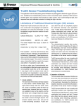
FIG. 2-1 Chip function structure diagram
© 2014 HYCON Technology Corp
www.hycontek.com
UG-HY16F198-V01_TC
page14
HY16F19 series user manual
21-bit ENOB Σ∆ADC,32-bit MCU & 64 KB Flash
2.2. CPU core block diagram
2-wire debug port
EDM
32-bit N801 Core
Boost ROM
Flash ROM
Instruction
.
Fetch
Load/Store
Unit
SRAM
Bus Interface Unit
APB
Digital
IP
Analog
IP
Sensor
IP
Communication
IP
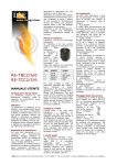
FIG. 2-2 CPU core block diagram
© 2014 HYCON Technology Corp
www.hycontek.com
UG-HY16F198-V01_TC
page15
HY16F19 series user manual
21-bit ENOB Σ∆ADC,32-bit MCU & 64 KB Flash
3. MEMORY STRUCTURE
3.1. Memory description
The core of the CPU (Central Processing Unit) of HY16F19 series products is Andes
N801 32-bit CPU. The allocation of the memory addresses of the micro controller is as
follows:
0x00000 to 0x01FFF Static random-access memory (SRAM) (8K Byte)
0x40000 to 0x4FFFF SOC Register
0x80000 to 0x81FFF Boot ROM (8K Byte)
0x90000 to 0x9FFFF Main Program Flash ROM (64K Byte)
.
FIG. 3-1 Memory address allocation diagram
© 2014 HYCON Technology Corp
www.hycontek.com
UG-HY16F198-V01_TC
page16
HY16F19 series user manual
21-bit ENOB Σ∆ADC,32-bit MCU & 64 KB Flash
3.2. Memory address
The detailed address allocation of the SOC registers of the micro controller is as
follows:
Function
module
Description
Base Address
INT
Interrupt Flag
0x40000
SoC
System control register
0x40100
CLK
Clock system control register
0x40300
PMU
Power management control register
0x40400
MC
Memory controller register
0x40600
PIO
GPIO port control register
0x40800
TMR
Timer register
0x40C00
UART
UART mode control register
0x40E00
SPI
SPI mode control register
0x40F00
I2C
I2C mode control register
0x41000
ADC
Analog-to-Digital module control register
0x41100
DAC
Digital-to-Analog module control register
0x41700
CMP
Comparator network module.control register
0x41800
Operational amplifier control register
0x41900
Real time clock control register)
0x41A00
OPAMP
RTC
Table 3-1 SOC registers
Some important registers have MASK bits, as describe in FIG. 3.3. MASK is used to
control written-in bits; only when the MASK bit corresponding to the control bit is <1>, the
corresponding control bit can be written in, or the written-in operation will be invalid and
cannot actually modify the value of the register, as shown in FIG. 3-2.
The total length of a register is 32-bit and most registers have 16 MASK bits. The
MASK bits include two 8-bit groups, and each 8-bit group controls corresponding 8 control
register bits. According to the content allocation of a register: BIT[31:24] controls
BIT[23:16], and BIT[15:8] controls BIT[7:0]. Only when the MASK bit is <1>, the
corresponding control bit can be validly written in.
For example, if a user wants to write 101010b in BIT[5:0] and the write value of the
register should be: 0011111100101010b, where 00111111b are the MASK bits of BIT[5:0]
and can make written-in corresponding control bits valid; and 00101010b are the values
written in BIT[5:0].
INT Base Address + 0x10 (0x40010)
Symbol
INTPT1 (PT1 Interrupt Control Register)
Bit
[31:24]
[23]
[22]
[21]
[20]
[19]
[18]
[17]
[16]
Name
MASK
PT17IE PT16IE PT15IE PT14IE PT13IE PT12IE PT11IE PT10IE
© 2014 HYCON Technology Corp
www.hycontek.com
UG-HY16F198-V01_TC
page17
HY16F19 series user manual
21-bit ENOB Σ∆ADC,32-bit MCU & 64 KB Flash
RW
Bit
Name
RW
R0W-0
[15:08]
MASK
R0W-0
RW-0
[7]
[6]
[5]
[4]
[3]
[2]
[1]
[0]
PT17IF PT16IF PT15IF PT14IF PT13IF PT12IF PT11IF PT10IF
RW0-0
FIG. 3-2 Basic structure of register
.
© 2014 HYCON Technology Corp
www.hycontek.com
UG-HY16F198-V01_TC
page18
HY16F19 series user manual
21-bit ENOB Σ∆ADC,32-bit MCU & 64 KB Flash
3.3. Static random-access memory (SRAM)
HY16F198 has a 8Kbyte SRAM. The initial address is from 0x00000 to 0x02000.
MCU can select to access one byte, half word or one word. MCU can access one word
during each clock cycle.
3.4. Flash ROM
HY16F198 has a 64Kbyte embedded Flash ROM. The initial value is from 0x90000
to 0x9FFFF. User programmable codes are stored in the Flash ROM. A user needs to
use CPU instructions to read and write the Flash ROM if wanting to edit the program codes
of the Flash ROM. The user can store data at any positions between the blocks.
3.5. Bus interface unit
Regarding the structure of a bus, the reading and writing of the register are controlled
by a 32-bit advanced peripheral bus (APB), which can write in 32-bit data during each clock
cycle. In order to prevent from the existing data be covered when writing in new data, the
user can use the MASK function to finish the operation.
.
As described in FIG. 3.3, the original data in BIT[7:0] of the register are 10101010b,
and the written-in data are made valid via the MASK bits; when 0000111101010101b are
written in BIT[15:0], the result will be 0000000010100101b, which means the MASK bit can
only be set as 1b and the read value will be 0b; when 0101b are written in BIT[7:4], but the
definition of BIT[15:13] is 000b; therefore, it means the write values of BIT[7:4] are invalid;
when 0101b are written in BIT[3:0] and the definition of MASK BIT[11:8] is 1111b; therefore,
it means the write values of BIT[3:0] can be valid.
O riginal D ata B yte
1
0
1
0
1
W rite instruction
0
0
0
0
0
1
0
0X A A
W rite D ata B yte
1
1
M A S K B yte
1
1
0
1
0
1
0
1
0
1
0X 0F 55
R esult
1
0
1
0
0
1
0
1
0X A 5
FIG. 3-3 Data flow structure
3.6. Boot ROM
8Kbyte Boot ROM is provided, and the initial value is from 0x80000 to 0x81FFF. The
© 2014 HYCON Technology Corp
www.hycontek.com
UG-HY16F198-V01_TC
page19
HY16F19 series user manual
21-bit ENOB Σ∆ADC,32-bit MCU & 64 KB Flash
blocks are for boot codes, flash codes and security codes. When the chip is reset, the
program timer will start from 0x80000. The software of the Boot ROM includes many
information, such as system program protocol, security protocol and the like.
.
© 2014 HYCON Technology Corp
www.hycontek.com
UG-HY16F198-V01_TC
page20
HY16F19 series user manual
21-bit ENOB Σ∆ADC,32-bit MCU & 64 KB Flash
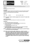
3.7. Embedded debug module (EDM)
The embedded debug module (EDM) is a debug interface which can be used by the
chip in the development environment. When the chip has no security protection, the user
can transmit instructions to the MCU via EDM interface to read the information of the debug
mode. EDM is the bridge of the communication between the chip and the computer The
PC USB and the chip EDM are connected via HY-Protocol (USB control board) by only
using a two-wire protocol interface. EDM can access the control register, general GPR
register, SRAM DLM and Flash ROM ILM of a chip.
PC/NB/Tablet
HY16F19x
32-bit MCU
AndeSight
GCC
HY-Protool,
USB control
Board
2-Wire
EDM
USB2.0
FIG. 3-4 Chip development connection diagram
.
© 2014 HYCON Technology Corp
www.hycontek.com
UG-HY16F198-V01_TC
page21
HY16F19 series user manual
21-bit ENOB Σ∆ADC,32-bit MCU & 64 KB Flash
4. SOC REGISTER
4.1. Overall description
Manage the operating mode of the system and the reset status of the chip, such as
WDT, external reset, under voltage reset, etc.
4.2. Register address
SoC Status Register Address
SoC Status Base Address + 0x04(0x40104)
-Reserved
31
24
-
23
16
-
15
8
MASK0
7
0
REG0
4.3. Register function
Operate the register SoC[4] can set the operating mode of the system as SLEEP
mode/IDEL mode/WAIT mode. The user can check the register SoC[3:0] to understand
what the current operating mode of the system is. The setting of the operating mode of
the chip will be specified at the chapter 25.
4.3.1. SOC register
Symbol
Bit
Name
RW
Bit
[15:8]
Name MASK
RW
R0W-0
Bit
Name
SoC Status Base Address + 0x04 (0x40104)
SoC Status Register
[31:24]
[23:16]
.
ICE Configuration
SoC Configuration
R-0Fh
R-C0h
[7]
[6]
[5]
[4]
[3]
[2]
[1]
F PRG
F CRst
IDLE F SLP/IDLE F WDog
F RST
RW-0
RW0-0
RW-0
RW0-0
[0]
F BOR
RW0-1
Description
Power Good Flag
Bit[06]
F PRG
0
Normal
1
Power Good has already been triggered before.
CPU Core Reset Flag
Bit[05]
F CRST
0
Normal
1
ICP Core has already been triggered before.
IDEL Mode Control Bit
Bit[04]
Bit[03]
IDLE
F SLP/IDLE
0
Sleep Mode
1
IDLE Mode
Sleep/Idle Flag
bit.)
0
© 2014 HYCON Technology Corp
www.hycontek.com
(Low voltage reset or reset circuit reset can reset the
Normal
UG-HY16F198-V01_TC
page22
HY16F19 series user manual
21-bit ENOB Σ∆ADC,32-bit MCU & 64 KB Flash
1
Sleep Mode or Idle Mode
WDT Flag (Low voltage reset or external reset can clear the bit.)
Bit[02]
F WDT
0
Normal
1
WDT is reset or interrupted.
External Reset Flag (Low voltage reset (BOR) can clear the bit.)
Bit[01]
Bit[00]
F RST
F BOR
0
Normal
1
PT4.0 reset or ICP software reset has occurred.
Low Voltage Reset (BOR) Flag (The bit will be automatically cleared after
the voltage of the chip is higher than 1.8V.)
0
Normal
1
Low voltage reset has occurred.
.
© 2014 HYCON Technology Corp
www.hycontek.com
UG-HY16F198-V01_TC
page23
HY16F19 series user manual
21-bit ENOB Σ∆ADC,32-bit MCU & 64 KB Flash
5. POWER MANAGEMENT
5.1. Overall description
Power management module includes a charge pump regulator, a wide BandGap
reference, a narrow BandGap reference, a VDDA LDO, a VDD18 LDO and a reference
output buffer. Chip VDD3V can work by only one voltage source between 2.2V and 3.6V.
The power system can be classified into three parts: I/O circuit, analog circuit, and digital
circuit. The power supply of the I/O circuit is driven by VDD3V. The power supply of the
analog circuit is driven by the internal VDDA LDO. Finally, the power supply of the digital
circuit is driven by VDD18 LDO.
When the MCU is under IDEL mode, it will use lowest power consumption to perform
the memory operation of the register and the SRAM. During the IDEL mode, the wide
BandGap reference, BOR and VDD18 LDO are enabled. If the MCU is under the
automatic wake-up mode, the low-speed oscillator should be enabled.
1uF
CL
CH
10μF
CP_I
CP_O
10μF
10μF
VDD3V
VLCD
ENCHP[0]
.
CP_CLK
ENCHP[0]
LCD_CLK
EN_LCD_CP
LCDV[1:0]
Charge Pump + Regulator
(CP_O ~ 3.3V)
ENBGR[0]
ENVA[0]
VDAS[0]
VCM
Buf
1μF
VDDA
1μF
BGR
EN_REFO
ACMS[0]
1
Regulator
VDDA
(2.4/2.7/3.0/3.3)
VDDA
ADC common
voltage
VDD18
LCD Charge
Pump
(2.6/2.8/3.0/3.3)
EN_REFO
REFO
Buf
REFO
0.1μF
ACMS[0]
0
REFO_I
PT3.6_ENI
VSS
FIG. 5-1 Function block diagram
© 2014 HYCON Technology Corp
www.hycontek.com
UG-HY16F198-V01_TC
page24
HY16F19 series user manual
21-bit ENOB Σ∆ADC,32-bit MCU & 64 KB Flash
Chip operating voltages VDD3V and VDD18
The operating voltage of the chip is inputted via the pin VDD3V, and the voltage range
is 2.2V~3.6V; besides, the pin should be connected to a 10uF ground capacitor, which can
make VDD3V become more stable. If the operating voltage of the chip is used to drive a
high current load, the operating voltage of the chip may be decreased and the chip may be
reset; in this situation, it is necessary to enable the charge pump boost circuit to output a
stable voltage to VDD3V via the CP_O pin so as to make sure the chip can work normally.
The VDD18 LDO output a stable voltage 1.8V via the VDD18 pin and the pin should be
connected to a 1uF bypass capacitor. The VDD18 LDO has a low-power voltage mode;
the register PMU[0] (VDDLP) should be set as 1 to achieve lowest power consumption.
Before the control bit enters the IDEL mode, the user can set it as 1; after the MCU is
wakened, the bit will be cleared to be 0.
VDDA voltage
The chip has a voltage regulator circuit LDO:VDDA, and the VDDA voltage should be
enabled when using ADC. It can have different operating modes and different output
voltages. It has four different operating modes; the first mode is to be short-circuited to the
VDD3V; and the VDDA is close to the VDD3V during the mode. The second mode is
Weak pull down; during the mode, the CDDA is close to the VSS. The third mode is High
.
Z; and it is possible to input the voltage into the CDDA from outside but the inputted voltage
should not exceed VDD3V. The four mode is adjustable voltage regulating mode LDO;
during the mode, the VDDA can output four different voltages: 2.4V, 2.7V, 3.0V and 3.3V.
For better performance, the voltage difference between VDD3V and VDDA. Should be
higher than 0.2V and can drive at most 10mA. Additionally, it also needs to be connected
to a 1uF bypass capacitor.
Low voltage detection circuit (BOR)
The BOR circuit is used to monitor the stability of the power system and the MCU.
When the BOR detects the VDD3V and VDD18 are lower the detecting voltage of the BOR,
the BOR will be triggered to reset the system and the chip; the chip will work normally until
the BOR detects the operating voltage of the chip exceeds the voltage of the BOR.
Charge Pump
The charge pump regulator provides stable voltage for the chip, which can also be
used to separate the power supply of the system from the power supply of the chip. Some
applications will need to use high current external circuit, such as driving a DC motor; in this
case, it is necessary to enable the charge pump to make sure the operating voltage of the
chip is stable and the interference caused by the surge current from the inductors of the
© 2014 HYCON Technology Corp
www.hycontek.com
UG-HY16F198-V01_TC
page25
HY16F19 series user manual
21-bit ENOB Σ∆ADC,32-bit MCU & 64 KB Flash
motor can be reduced.
So as to enable the charge pump, the register PMU[2] should be set as 1 and the ADC
clock source should be enabled; the external circuit needs connect an external capacitor
(Ccp2) in series between the CH/CL pins, and respectively connect an external ground
capacitor to the CP_I/CP_O pins; the voltage regulating output end CP_O of the charge
pump should be short-circuited to the operating voltage pin VDD3V of the chip. When the
charge pump is working, the power supply is inputted from the CP_I to generate and output
stable voltage from CP_O to the input of the VDD3V. If the charge pump is not enabled,
the voltage of the CP_O will be equal to the voltage of the CP_I; and the voltage will be also
outputted from the CP_O to the input of the VDD3V. If the charge pump boot circuit will
not be used, it is not necessary to install the external capacitors Ccp2, Ccp1 and Ccp3; the
operating voltage of the chip will be directly provided by VDD3V.
When the charge pump is working, it is suggested that the capacitances of the CH/CL
pins are 1uF and cannot be lower than 0.1uF. It is suggested that the capacitance of the
CP_O is at least ten times the capacitance of the capacitors connected in series between
the CH/CL pins. If the capacitance of the CH/CL pins is 1uF, it is suggested that the
capacitance of the CP_O is higher than or equal to 10uF. If the capacitance of the CP_O
is large, the system will be more stable. The connection of the output of the CP_O and the
pins of VDD3V should be done by short circuit from the external PCB.
.
BandGap reference voltage and common mode voltage (REFO)
When the VDDA is higher than 2.4V, the analog circuit can work. However, the
analog circuit needs the current offset and the reference voltage. Therefore, the BandGap
reference voltage should be enabled before the analog circuit is enabled; the BandGap
reference voltage can be enabled by setting the register PMU[4](ENBGR) as 1. Only after
the BandGap reference voltage is enabled, the common mode voltage (REFO) can
effectively output 1.2V.
It is necessary to provide a common mode voltage (REFO) for the ADC to enable it. If
the user wants to use the internal power supply, the ACMS should be set as 1; if the user
wants to the external power supply, the ACMS should be set as 0 to output a common
mode voltage (REFO). The user will need to use a reference voltage to drive the external
circuit; therefore, the ENRFO should be set as 1 to output the common mode voltage to the
pin; besides, the REFO is the BandGap reference voltage with buffer. The output voltage
of the REFO pin is about 1.2V and has 200uA push-pull driving ability. It can drive a
22~1000nF big capacitor load. If the external REFO voltage output is used, the common
mode voltage for the ADC can be provided by an external power supply; in this case, the
ACMS can be set as 0 to save more power.
© 2014 HYCON Technology Corp
www.hycontek.com
UG-HY16F198-V01_TC
page26
HY16F19 series user manual
21-bit ENOB Σ∆ADC,32-bit MCU & 64 KB Flash
The following table shows the voltage sources for all modules.
Table 5-1 Chip Power supply distribution
Block name
Voltage source
Block name
Voltage
Source
32-bit CPU Core N801
VDD18
Timer A/B/C PWM
VDD18
08KB SRAM
VDD18
GPIO Port
VDD3V
64KB Flash ROM
VDD3V/ VDD18
24-bit SD ADC
VDDA
Clock System
VDD18
08-bit DAC
VDDA
Watch Dog Timer
VDD18
Rail-to-Rail OPAMP
VDDA
Hardware RTC
VDD18
Analog Comparator
VDD3V
Charge Pump
VIN
BOR
VDD3V/ VDD18
Band Gap/Reference
VDDA
Hardware EUART
VDD18/VDD3V
32-bit Hardware SPI
VDD18/VDD3V
Hardware I2C
VDD18/VDD3V
.
© 2014 HYCON Technology Corp
www.hycontek.com
UG-HY16F198-V01_TC
page27
HY16F19 series user manual
21-bit ENOB Σ∆ADC,32-bit MCU & 64 KB Flash
5.2. Register address
Power Management Register Address
PMU Base Address + 0x00 (0x40400)
31 24
MASK1
23 16
REG1
15
8
MASK0
7
0
REG0
5.3. Register function
5.3.1. Power management register (PMU)
Symbol
Bit
Name
RW
Bit
Name
RW
Power Management Base Address + 0x00 (0x40400)
PMU (PMU Control Register )
[31:28]
[27:24]
[20]
[19:18]
[17:16]
Rsv
Mask
Reg
VDAS
ENVA
R-0
R0W-0
RW-0
RW-0
[15:08]
[7:6]
[5]
[4]
[3]
[2]
[1]
[0]
MASK
ENBGR ACMS ENCHP ENRFO VDDLP
R0W-0
RW-0
Bit
Name Description
VDDA output voltage selection
Bit[19~18]
00
VDDA =2.4V
VDAS 01
VDDA =2.7V
10
VDDA =3.0V
11
VDDA =3.3V
.
VDDA LDO voltage source configuration for controlling
the output voltage range of the VDDA.
Bit[17~16]
ENVA
00
High impedance (High Z)
01
Internally short-circuited to the VDD3V;
the output of the VDDA is close to the VDD3V
10
Weak pull down; the output of he VDDA is close to the VSS.
11
VDDA LDO; the output of the VDDA can be adjusted
, which is decided by the VDAS.
Band Gap voltage enablement control
Bit[04]
ENBGR 0
1
Disable
Enable (when ENVA=11b, it will be automatically enabled.)
ADC analog ground input source selection
Bit[03]
ACMS 0
1
External analog ground
Internal analog ground (used with the ADC)
Charge Pump enablement control
Bit[02]
ENCHP 0
Disable
1
Enable
© 2014 HYCON Technology Corp
www.hycontek.com
UG-HY16F198-V01_TC
page28
HY16F19 series user manual
21-bit ENOB Σ∆ADC,32-bit MCU & 64 KB Flash
Common mode voltage (REFO) enablement control
Bit[01]
ENRFO 0
Disable
1
Enable
VDD18 LDO low-power control
Bit[00]
VDDLP 0
1
Normal (the bit should be set as 0 after the SLEEP mode.)
Low-power
.
© 2014 HYCON Technology Corp
www.hycontek.com
UG-HY16F198-V01_TC
page29
HY16F19 series user manual
21-bit ENOB Σ∆ADC,32-bit MCU & 64 KB Flash
6. CLOCK SYSTEM
6.1. Overall description
The clock control system provides the clocks for the whole chip, including the system
clocks (CPU clock, APB clock) and all peripheral operating clocks (timer, communication
interface, RTC, analog circuit, etc.) Each function module has a clock switch controller,
clock source selection and frequency divider. Under the SLEEP mode, the controller
always closes the external crystal oscillators, internal crystal oscillators and system clocks
to minimize the system power consumption.
The operating clock sources include the external crystal oscillators, internal HAO and
LPO oscillators; with the frequency divider, the frequency sources of the CPU and the
peripheral devices can be flexibly allocated and managed to adjust the power consumption
of the chip in order to save the energy.
6.1.1. External oscillators
There are two external oscillators, including the high-speed crystal oscillator (HSXT)
and the low-speed crystal oscillator (LSXT). The chip has two independent input pins for
the external high-speed crystal oscillator and low-speed crystal oscillator; thus, the user can
connect the two external oscillators to the chip at the same time. The external oscillator
should be connected to a resistor in parallel, or the crystal oscillator will not work even if it is
soldered at the pin; besides, the crystal oscillator can be connected to two 10~20pF ground
.
capacitors and the capacitance of each capacitor is subject to the parasitic capacitor
caused by the layout of the PCB.
The parallel resistor between the pins of the oscillator and the capacitor C2/C1
parameters of each pin of the oscillator will vary with the frequency, brand of the external
crystal oscillator and the layout of the PCB. The following table lists suggested allocation
of the R1/C1/C2 parameters and the frequency sources for your reference.
External crystal oscillator parameters
Type
Symbol
Instruction execution
status
Frequency
R1/Ω
C1
C2
Sleep
mode
Idle
mode
Low-speed
oscillator
LSXT
32768HZ
10M
10pF
10pF
Stop
Available
High-speed
oscillator
HSXT
2~16MHZ
1M
10pF
10pF
Stop
Available
6-1 Suggest external crystal oscillator configuration
Matter needing attentions of using external crystal oscillators:
The operating voltage of the chip should be kept high when using a 16MHZ oscillator
or above.
The stabilization time of the external 4MHZ/8MHZ crystal oscillators is about 25ms,
© 2014 HYCON Technology Corp
www.hycontek.com
UG-HY16F198-V01_TC
page30
HY16F19 series user manual
21-bit ENOB Σ∆ADC,32-bit MCU & 64 KB Flash
and that of the external 32768HZ crystal oscillator is about 1.3s.
After the SLEEP instruction is executed, all external crystal oscillators will stop.
Please pay attention to the I/O configuration of the pins when connecting to external crystal
oscillators; when using the external crystal oscillators, the pins configuration should be set
as input mode and no internal pull-up resistor is used so as to make sure they can work
normally. Besides, the external resistors are necessary.
.
© 2014 HYCON Technology Corp
www.hycontek.com
UG-HY16F198-V01_TC
page31
HY16F19 series user manual
21-bit ENOB Σ∆ADC,32-bit MCU & 64 KB Flash
6.1.2. Internal crystal oscillators HAO and LPO
The HAO is an external high-speed RC oscillator of the chip and its typical output
frequency is 2MHZ/4MHZ/10MHZ/16MHZ; besides, it has several features, such as quick
start, high anti-interference and low power consumption, etc. The output frequency of the
HAO is adjustable; therefore, the user can adjust the output frequency of the HAO by
software.
Matter needing attentions of using internal crystal oscillators:
The operating voltage of the chip should be kept high when using the 16MHZ HAO.
The output frequency of the HAO can be adjusted by modifying the register HAOTR.
The default oscillator of the chip is the internal 2MHZ HAO; the user can modify the default
settings and change the output frequencies of other HAOs.
The stabilization time of the 4MHZ HAO is about 0.5ms;
After the SLEEP instruction is executed, all HAO oscillators will stop and enter the SLEEP
mode.
After the IDEL instruction is executed, all HAO oscillators will not stop, but the CPU will
enter the IDEL mode.
The LPO is the internal low-speed RC oscillator of the chip; its output frequency is 35kHZ
and has low power consumption; it will immediately start after the chip is power-on or
.
wakened; besides, it cannot be enabled; in other words, the LPO will keep working during
the whole operation process of the chip.
The stabilization time of the LPO is about 510us and it is the only operating clock source of
the WDT.
After the SLEEP instruction is executed, all LPO oscillators will stop.
After the IDEL instruction is executed, all LPO oscillators will not stop, but the CPU will
enter the IDEL mode.
Typical output frequencies of the HAO and LPO are as shown in following Table 6-2.
Symbol
HAO
LPO
Frequency
Frequency source configuration
Instruction execution
status
ENHAO[1]
HAO[1:0]
CKHS[1]
Sleep
Idle
2MHZ
1
00B
0
Stop
Workable
4MHZ
1
01B
0
Stop
Workable
10MHZ
1
10B
0
Stop
Workable
16MHZ
1
11B
0
Stop
Workable
CKLS=0
Stop
Oscillate
35KHZ
Start after the chip is
power-on
Table 6-2
© 2014 HYCON Technology Corp
www.hycontek.com
Internal crystal oscillator configuration
UG-HY16F198-V01_TC
page32
HY16F19 series user manual
21-bit ENOB Σ∆ADC,32-bit MCU & 64 KB Flash
6.1.3. CPU and external peripheral operating frequency sources configuration
Both of the external and internal crystal oscillators can provide the frequency sources
for the CPU and the frequency sources will be provided for the CPU after passing the
frequency dividers. The chip can determine the frequency source of the CPU is the
HS_CK or LS_CK via the frequency selector MCUCKS[1] and perform the frequency
division via the frequency divider ENMCD[1]. Thus, there are multiple operating frequency
modes for the CPU to select from to determine the instruction cycle of the chip.
Similarly, the external peripheral operating frequency sources are also provided by the
external, internal crystal oscillators and the HS_CK or LS_CK passing the frequency
dividers; or the frequency sources can be directly provided by the crystal oscillators, such
as the WDT. As the external peripheral operating frequency configuration may vary with
the different operations, please refer to the following figure for more information.
HSXT Enable(ENOHS)
2~20MHz
ENHAO[0]
HAO[1:0]
HAOTR[7:0]
HSXT
2 ~20MHz
HSRC
2/4/10/16M
Hz
CKHS[0]
HSXT
HSRC
MCUCKS[0]
LSXT
LSRC
35KHz
LSRC
© 2014 HYCON Technology Corp
www.hycontek.com
1
CKLS[0]
LSXT
32.768KHz
Table 6-1
0
.
LSXT Enable(ENOLS)
32.768KHz
HS_CK
1
0
1
0
ENMCD[0]
Pre-scale
1,2
MCCK
APCK
CPU
APB
LS_CK
CPU operating frequency source configuration diagram
UG-HY16F198-V01_TC
page33
HY16F19 series user manual
21-bit ENOB Σ∆ADC,32-bit MCU & 64 KB Flash
ENACD[0]
Pre-scale
6,12,30,60
HS_CK
CKS[0]
LSXT
0
LSRC
1
CKH[0]
Pre-scale
1
MCCK
ADCK
ADC
ENADC[0]
RTCEn[0]
0
ADCD[1:0]
RTCK
ADCK
RTC
ADCKo
0
Pre-scale CHPCK
4
1
Charge
Pump
(internal used only)
En[0]
SPCD[2:0]
Pre-scale
1,2,4,
~2048
APCK
SPCK
ENWDT[0]
SPI
I2CEn[0] CRG[7:0]
Pre-scale
APCK
TUCK[0]
HSXT
0
HSRC
1
UT2CKS[0]
ENUD[0]
Pre-scale
1,2,4,~128
HSRC
1
Pre-scale
1,2,4,~128
IOCKS[0]
IOCD[3:0]
LS_CK
1
URCK
UR2CK
IOCK
Pre-scale
1,2,4,~16384
Table 6-2
Pre-scale
256
TACKS[0]
ENTAD[0]
HS_CK
0
LS_CK
1
Pre-scale
32
WDCK
TACK
WDT
Timer A
TMCKS[0] ENTD[0] TMCD[1:0]
UART
HS_CK
0
LS_CK
1
Pre-scale
1,2,4,8
TBCK
Timer B
Timer C
TM2CKS[0] ENT2D[0] TM2CD[1:0]
ENU2D[0] UA2CD[3:0]
0
0
I2C
UACD[3:0]
HSXT
HS_CK
I2CK
LSRC
UART2
.
HS_CK
0
LS_CK
1
LCKS[0]
PTIO
LS_CK
0
HS_CK
1
Pre-scale
1,2,4,8
TB2CK
Timer B2
LCDE[3:0] LCDO[1:0]
Pre-scale
LCK
LCD
External peripheral operating frequency configuration diagram
6.2. Register address
Clock Register Address
CLK Base Address + 0x00 (0x40300)
CLK Base Address + 0x04 (0x40304)
CLK Base Address + 0x08 (0x40308)
CLK Base Address + 0x0C (0x4030C)
CLK Base Address + 0x10 (0x40310)
CLK Base Address + 0x14 (0x40314)
-Reserved
© 2014 HYCON Technology Corp
www.hycontek.com
31
24
MASK1
MASK3
MASK5
-
23
16
REG1
REG3
REG5
-
15
8
MASK0
MASK2
MASK4
MASK6
MASK7
7
0
REG0
HAOTR
REG2
REG4
REG6
REG7
UG-HY16F198-V01_TC
page34
HY16F19 series user manual
21-bit ENOB Σ∆ADC,32-bit MCU & 64 KB Flash
6.3. Register function
6.3.1. Clock system register CLKCR0
Symbol
Bit
Name
RW
Bit
Name
RW
Bit
[15:8]
MASK
R0W-0
Name
Clock Base Address + 0x00 (0x40300)
CLK0 (Clock Control Register 0)
[31:16]
RSV(Reserved)
R-0
[7]
[6]
[5]
[4:3]
[2]
[1]
[0]
OHS_HS CKLS
CKHS
HAO
ENOLS ENOHS ENHAO
RW-0
RW-1
Description
External oscillator mode selection
Bit[7]
OHS_HS 0
HSXT<4MHz
1
HSXT>4MHz
Chip low-speed frequency source selection
Bit[6]
CKLS
0
Internal low-speed oscillator (OSC_LSRC)
1
External low-speed oscillator (OSC_LSXT)
Chip high-speed frequency source selection
Bit[5]
CKHS
.
0
External low-speed oscillator (OSC_HSRC)
1
External high-speed oscillator (OSC_HSXT)
Internal high-speed oscillator mode configuration
[00] 2MHz
Bit[4~3]
HAO
[01] 4MHz
[10] 10MHz
[11]
16MHz
External low-speed oscillator enablement control
Bit[02]
ENOLS
0
Disable
1
Enable
External high-speed oscillator enablement control
Bit[01]
ENOHS
0
Disable
1
Enable
Internal high-speed oscillator enablement control
Bit[00]
ENHAO
© 2014 HYCON Technology Corp
www.hycontek.com
0
Disable
1
Enable
UG-HY16F198-V01_TC
page35
HY16F19 series user manual
21-bit ENOB Σ∆ADC,32-bit MCU & 64 KB Flash
6.3.2. Clock system register CLKCR1
Clock Base Address + 0x04 (0x40304)
CLK1 (Clock Control Register 1)
[31:16]
Reserved
R-0
[15:8]
[7:0]
Reserved
HAOTR
R-0
RW-80H
Symbol
Bit
Name
RW
Bit
Name
RW
Bit
Name
Description
Internal high-speed oscillator calibration control register
Bit[7:0]
HAOTR
0
Set 0
1
Set 1
1*LSB.Step = 0.125%
0000_0000 is the lowest speed.
1000_0000 is the default speed.
1111_1111 is the higher speed.
6.3.3. Clock system register CLKCR2
Symbol
Bit
Name
RW
Bit
Name
RW
Bit
Clock Base Address + 0x08 (0x40308)
CLK2 (Clock Control Register 2)
[23]
[22]
[21]
[20]
[19:16]
ENRTCK
TUCKS
ENUD
UACD
RW-0
RW-0
[7]
[6]
[5:4]
[3]
[2]
[1]
[0]
TMCKS ENTD TMCD TACKS ENTAD ENMCD MCUCKS
RW-0
[31:24]
MASK
R0W-0
[15:08]
MASK
R0W-0
Name
.
Description
RTC clock source control
Bit[23]
ENRTCK 0
1
Disable (The RTC register cannot be written in and unlocked.)
Enable (The RTC register can be unlocked.)
EUART clock source selection
Bit[21]
TUCKS 0
HSXT: External high-speed oscillator
1
HSRC: Internal high-speed oscillator
EUART clock source enablement control
Bit[20]
ENUD 0
Disable
1
Enable
© 2014 HYCON Technology Corp
www.hycontek.com
UG-HY16F198-V01_TC
page36
HY16F19 series user manual
21-bit ENOB Σ∆ADC,32-bit MCU & 64 KB Flash
EUART clock source frequency divider configuration
0000 EUART clock source/ 1
0001 EUART clock source/ 2
0010 EUART clock source/ 4
0011 EUART clock source/ 8
Bit[19~16]
UACD 0100 EUART clock source/ 16
0101 EUART clock source/ 32
0110 EUART clock source/ 64
0111 EUART clock source/ 128
1000
~1111 Reserved
Timer B,C clock source selection
Bit[07]
TMCKS 0
HS_CK
1
LS_CK
Timer B,C clock source enablement control
Bit[06]
ENTD
0
Disable
1
Enable
Timer B,C clock source frequency divider configuration
Bit[5~4]
00
clock/1
TMCD 01
clock/2
10
clock/4
11
clock/8
.
Timer A clock source selection
Bit[03]
TACKS 0
HS_CK
1
LS_CK
Timer A clock source frequency divider configuration
Bit[02]
ENTAD 0
1
Disable the frequency divider
Timer A clock/32
MCU input clock source frequency divider configuration
Bit[01]
ENMCD 0
MCU clock/1
1
MCU clock/2
MCU input clock source selection
Bit[00]
MCUCKS 0
HS_CK
1
LS_CK
© 2014 HYCON Technology Corp
www.hycontek.com
UG-HY16F198-V01_TC
page37
HY16F19 series user manual
21-bit ENOB Σ∆ADC,32-bit MCU & 64 KB Flash
6.3.4. Clock system register CLKCR3
Symbol
Bit
Name
RW
Bit
Name
RW
Bit
Bit[20]
[31:24]
MASK
R0W-0
[15:08]
MASK
R0W-0
Clock Base Address + 0x0C (0x4030C)
CLK3 (Clock Control Register 3)
[23:21]
[20]
[19:16]
IOCKS
IOCD
RW-0
[7]
[6]
[5:4]
[3]
[2:0]
ADCKP
ENACD
ADCD
ENSD
SPCD
RW-0
Name Description
GPIO input clock source selection
IOCKS 0
HS_CK
1
LS_CK
GPIO clock frequency divider configuration
0000
Disable
0001
GPIO clock source/ 1
0010
GPIO clock source/ 2
0011
GPIO clock source/ 4
0100
. 8
GPIO clock source/
0101
GPIO clock source/ 16
0110
GPIO clock source/ 32
Bit[19~16] IOCD 0111
GPIO clock source/ 64
1000
GPIO clock source/ 128
1001
GPIO clock source/ 256
1010
GPIO clock source/ 512
1011
GPIO clock source/ 1024
1100
GPIO clock source/ 2048
1101
GPIO clock source/ 4096
1110
GPIO clock source/ 8192
1111
GPIO clock source/ 16384
ADC clock phase shift(effective only at Core Clock/2 and Core Clock is HS_CK)
Bit[7]
ADCKP 0
ADC Clock Rising Edge generates from Core Clock Low
1
ADC Clock Rising Edge generates from Core Clock High
ADC clock switch
Bit[6]
Bit[5~4]
ENACD 0
Disable
1
Enable
ADCD ADC clock frequency divider configuration
© 2014 HYCON Technology Corp
www.hycontek.com
UG-HY16F198-V01_TC
page38
HY16F19 series user manual
21-bit ENOB Σ∆ADC,32-bit MCU & 64 KB Flash
00
ADC clock source/ 6
01
ADC clock source/ 12
10
ADC clock source/ 30
11
ADC clock source/ 60
SPI clock switch
Bit[3]
ENSD 0
Disable
1
Enable
ADC clock frequency divider configuration
Bit[2~0]
000
Reserved
001
SPI clock source/ 2
010
SPI clock source/ 4
SPCD 011
SPI clock source/ 8
100
SPI clock source/ 32
101
SPI clock source/ 128
110
SPI clock source/ 512
111
SPI clock source/ 2048
6.3.5. Clock system register CLKCR4
.
Symbol
Bit
Name
RW
Bit
Name
RW
Bit
[31:24]
MASK
R0W-0
[15:08]
MASK
R0W-0
Clock Base Address + 0x10 (0x40310)
CLK4 (Clock Control Register 4)
[23:22]
[21]
[20]
[19]
LCDCPD UT2CKS ENU2D
RW-0
[7]
[6:4]
[3:1]
LCDO
LCDE
RW-0
[18:16]
UA2CD
RW-0
[0]
LCKS
Name Description
LCD charge pump regulator clock source selection
0
LS_CK / 1 or HS_CK/8
(LCKS determines LS_CK or HS_CK)
Bit[22~23] LCDCPD 1
LS_CK / 2 or HS_CK/16
(LCKS determines LS_CK or HS_CK)
2
LS_CK / 4 or HS_CK/32
(LCKS determines LS_CK or HS_CK)
3
LS_CK / 4 or HS_CK/32
(LCKS determines LS_CK or HS_CK)
UART2 clock source selection
Bit[21]
Bit[20]
UT2CKS 0
HSXT: External high-speed oscillator
1
HSRC: Internal high-speed oscillator
ENUD2D UART2 clock source enablement control
0
© 2014 HYCON Technology Corp
www.hycontek.com
Disable
UG-HY16F198-V01_TC
page39
HY16F19 series user manual
21-bit ENOB Σ∆ADC,32-bit MCU & 64 KB Flash
1
Enable
UART2 clock source frequency divider configuration
0
UART2 clock source/ 1
1
UART2 clock source/ 2
2
UART2 clock source/ 4
Bit[18~16] UA2CD 3
UART2 clock source/ 8
4
UART2 clock source/ 16
5
UART2 clock source/ 32
6
UART2 clock source/ 64
7
UART2 clock source/ 128
LCD clock source 1-stage frequency divider configuration
Bit[6~4]
LCDO
0
Disable
1
LCD clock source/ 1
2
LCD clock source/ 2
3
LCD clock source/ 4
4
LCD clock source/ 8
5
LCD clock source/ 16
6
LCD clock source/ 32
7
Disable
.
LCD clock source 2-stage frequency divider configuration
Bit[3~1]
LCDE
0
LCD clock source/ 1
1
LCD clock source/ 3
2
LCD clock source/ 5
3
LCD clock source/ 7
4
LCD clock source/ 9
5
LCD clock source/ 11
6
LCD clock source/ 13
7
LCD clock source/ 15
LCD clock source selection
Bit[0]
LCKS
© 2014 HYCON Technology Corp
www.hycontek.com
0
LS_CK(always÷8)
1
HS_CK(always÷64)
UG-HY16F198-V01_TC
page40
HY16F19 series user manual
21-bit ENOB Σ∆ADC,32-bit MCU & 64 KB Flash
6.3.6. Clock system register CLKCR5
Symbol
Bit
Name
RW
Bit
Name
RW
Bit
Clock Base Address + 0x014 (0x403148
CLK5 (Clock Control Register 4)
[31:16]
Reserved
R-0
[15:8]
[7]
[6]
[5:4]
Mark
TM2CKS
ENT2D
TM2CD
R0W-0
RW-0
Name
[3:0]
-
Description
Timer B2 clock source selection
Bit[7]
TM2CKS 0
HS_CK
1
LS_CK
Timer B2 clock source enablement control
Bit[6]
ENT2D
0
Disable
1
Enable
Timer B2 clock source frequency divider configuration
Bit[5~4]
TM2CD
© 2014 HYCON Technology Corp
www.hycontek.com
0
Timer B2 clock source/ 1
1
Timer B2 clock source/ 2
2
Timer B2 clock source/ 4
3
Timer B2 clock source/ 8
.
UG-HY16F198-V01_TC
page41
HY16F19 series user manual
21-bit ENOB Σ∆ADC,32-bit MCU & 64 KB Flash
7. INTERRUPT CONTROL SYSTEM
7.1. Overall description
The interrupt module includes the interrupt startup controller, interrupt enable controller
and interrupt event flag register to manage the overall interrupt service, such as
communication interrupt, timer interrupt, ADC interrupt, comparator interrupt and IO
external interrupt. The chip provides 9-stage interrupt source and also provides 9-stage
interrupt vector priorities, including HW0, HW1…HW8 (from high priority to low priority).
The interrupt service is composed of the interrupt event flag (INTF), interrupt event service
intelligent startup (INTE), interrupt general control GIE and vector addresses HW0~HW8.
When the interrupt event occurs and the interrupt event service is enabled, the program
counter PC will turn to the interrupt service vector addresses HW0~HW8 of the program
memory at the next instruction cycle to execute the interrupt service program.
HW0中斷向量
HW1中斷向量
.
.
.
HW8中斷向量
中央處理器N8 GIE中斷設定
各IP中斷致能Interrupt Enable
各IP中斷致能Interrupt Flag
.
CPU N8 GIE interrupt settings
Interrupt enable of each IP
Interrupt enable of each IP
Interrupt vector
FIG. 7-1
Interrupt service structure diagram
Detail operation description:
The user can set the corresponding interrupt enable bit to be 1 or clear the bit to enable or
disable the corresponding interrupt function. The interrupt function can be enabled by
setting the corresponding interrupt enable bit to be 1.
After the interrupt event takes place, the interrupt flag will be generated; the user can clear
the flag to cancel the interrupt request.
It is necessary to set the global interrupt enable bit GIE=1, or any interrupt cannot be
enabled.
The interrupt vector priority will be determined when multiple interrupt requests take place
at the same time; the interrupt vector with high priority should be replied first.
During the execution of the interrupt vector service program, the high-level interrupt vector
© 2014 HYCON Technology Corp
www.hycontek.com
UG-HY16F198-V01_TC
page42
HY16F19 series user manual
21-bit ENOB Σ∆ADC,32-bit MCU & 64 KB Flash
cannot terminate the current interrupt service to execute the high-level interrupt service; the
high-level interrupt request can be executed only after the current interrupt vector service is
finished.
After the interrupt service program is finished, it will automatically return to the program
address where the interrupt occurred and continuously execute the program.
The corresponding interrupt vector program entry addresses of the interrupts of the chip are
as shown in the following table.
Interrupt Vector Address
Vector
Interrupt Function
INT Base Address + 0x00 (I2C,UART,SPI
HW0
void HW0_ISR(void)
communication interfaces)
INT Base Address + 0x04 (Timer ABC WDT HW RTC)
HW1
void HW1_ISR(void)
INT Base Address + 0x08 (ADC)
HW2
void HW2_ISR(void)
INT Base Address + 0x0C (CMP/OPA)
HW3
void HW3_ISR(void)
INT Base Address + 0x10 (PT1)
HW4
void HW4_ISR(void)
INT Base Address + 0x14 (PT2)
HW5
void HW5_ISR(void)
INT Base Address + 0x18 (Software Interrupt)
HW6
void HW6_ISR(void)
INT Base Address + 0x1C (UART2)
HW7
void HW7_ISR(void)
INT Base Address + 0x20 (TMB2)
HW8
void HW8_ISR(void)
7.2. Register address
.
Interrupt Register Address
INT Base Address + 0x00 (COM) (0x40000)
INT Base Address + 0x04 (TMR) (0x40004)
INT Base Address + 0x08 (ADC) (0x40008)
INT Base Address + 0x0C (CMP) (0x4000C)
INT Base Address + 0x10 (PT1) (0x40010)
INT Base Address + 0x14 (PT2) (0x40014)
INT Base Address + 0x18 (UART2) (0x40018)
INT Base Address + 0x1C (TMB2) (0x4001C)
31 24
MASK0
MASK2
MASK4
MASK6
MASK8
MASK10
MASK12
MASK14
23 16
REG0
REG2
REG4
REG6
REG8
REG10
REG12
REG14
15
8
MASK1
MASK3
MASK5
MASK7
MASK9
MASK11
MASK13
MASK15
7
0
REG1
REG3
REG5
REG7
REG9
REG11
REG13
REG15
-Reserved
7.3. Register function
7.3.1. Interrupt control register INTCOM
Symbol
Bit
Name
RW
Bit [15:14]
Name
RW
-
INT Base Address + 0x00 (0x40000)
INTCOM (Interrupt Control Register 0)
[31:24]
[23:22] [21] [20] [19] [18] [17] [16]
MASK
I2CEIE I2CIE UTxIE URxIE STxIE SRxIE
R0W-0
RW-0
[13]
[12] [11]
[10]
[9]
[8]
[7:6]
[5]
[4]
[3]
[2]
[1]
[0]
MASK
I2CEIF I2CIF UTxIF URxIF STxIF SRxIF
I2CEIR I2CIR UTxIR TRxIR STxIR SRxIR
R-0
RW0-0
(When writing the register, the Bit15~8 are Mask; when reading the register, the Bit1
© 2014 HYCON Technology Corp
www.hycontek.com
UG-HY16F198-V01_TC
page43
HY16F19 series user manual
21-bit ENOB Σ∆ADC,32-bit MCU & 64 KB Flash
5~8 are general registers.)
Bit
Bit[21]
Name Description
I2C error interrupt enable control
I2CEIE 0
Disable
1
Enable
I2C interrupt enable control
Bit[20]
I2CIE
0
Disable
1
Enable
UART transmits (TX) interrupt enable control
Bit[19]
UTxIE 0
Disable
1
Enable
UART receives (RX) interrupt enable control
Bit[18]
URxIE 0
Disable
1
Enable
SPI transmits (TX) interrupt enable control
Bit[17]
STxIE 0
Disable
1
Enable
SPI receives (RX) interrupt enable control
Bit[16]
SRxIE 0
Disable
1
Enable
.
I2C interrupt error request
Bit[13]
I2CEIR 0
1
Normal
Interrupt
I2C interrupt request
Bit[12]
I2CIR
0
Normal
1
Interrupt
UART Tx interrupt request
Bit[11]
UTxIR 0
1
Normal
Interrupt
UART Rx interrupt request
Bit[10]
TRxIR 0
1
Normal
Interrupt
SPI Tx interrupt request
Bit[9]
STxIR 0
1
Bit[8]
Normal
Interrupt
SRxIR SPI Rx interrupt request
© 2014 HYCON Technology Corp
www.hycontek.com
UG-HY16F198-V01_TC
page44
HY16F19 series user manual
21-bit ENOB Σ∆ADC,32-bit MCU & 64 KB Flash
0
Normal
1
Interrupt
I2C error interrupt flag (level-trigger)
Bit[05]
I2CEIF 0
1
Normal
I2C error takes place and interrupt occurs
I2C interrupt flag (level-trigger)
Bit[04]
I2CIF
0
Normal
1
I2C interrupt occurs
UART transmits (TX ) interrupt flag (level-trigger)
Bit[03]
UTXIF 0
1
Normal
UART transmission (TX ) interrupt occurs.
UART receives (RX) interrupt flag (level-trigger)
Bit[02]
URXIF 0
1
Normal
UART receives (RX) interrupt occurs.
SPI transmission (TX ) interrupt flag (level-trigger)
Bit[01]
STXIF 0
1
Normal
SPI transmission (TX) interrupt occurs.
SPI reception (RX) interrupt flag (level-trigger)
Bit[00]
SRXIF 0
1
Normal
.
SPI reception (RX) interrupt occurs.
7.3.2. Interrupt control register INTTMR
Symbol
Bit
Name
RW
Bit [15:14]
Name
RW
-
INT Base Address + 0x04 (0x40004)
INTTMR (Interrupt Control Register 1)
[31:24]
[23:22] [21]
[20]
[19]
[18]
[17]
[16]
MASK
RTCIE WDTIE TMC1IE TMC0IE TMBIE TMAIE
R0W-0
RW-0
[13]
[12]
[11]
[10]
[9]
[8]
[7:6]
[5]
[4]
[3]
[2]
[1]
[0]
MASK
RTCIF WDTIF TMC1IF TMC0IF TMBIF TMAIF
RTCIR WDTIR TMC1IR TMC0IR TMBIR TMAIR
R0W-0
RW0-0
(When writing the register, the Bit15~8 are Mask; when reading the register, the Bit15~8 are
general registers)
Bit
Name
Description
Real-time clock RTC interrupt enable control
Bit[21]
Bit[20]
RTCIE 0
Disable
1
Enable
WDTIE WDT interrupt enable control
0
© 2014 HYCON Technology Corp
www.hycontek.com
Disable
UG-HY16F198-V01_TC
page45
HY16F19 series user manual
21-bit ENOB Σ∆ADC,32-bit MCU & 64 KB Flash
1
Enable
TMC1 interrupt enable control
Bit[19]
TMC1IE 0
Disable
1
Enable
TMC0 interrupt enable control
Bit[18]
TMC0IE 0
Disable
1
Enable
Timer TMB interrupt enable control
Bit[17]
TMBIE 0
Disable
1
Enable
Timer TMA interrupt enable control
Bit[16]
TMAIE 0
Disable
1
Enable
RTC interrupt request
Bit[13]
RTCIR 0
Disable
1
Enable
WDT interrupt request
Bit[12]
WDTIR 0
Normal
1
Enable
.
Timer C channel 1 interrupt request
Bit[11]
TMC1IR 0
Normal
1
Enable
Timer C channel 0 interrupt request
Bit[10]
TMC0IR 0
Normal
1
Enable
TMB interrupt request
Bit[9]
TMBIR 0
Normal
1
Enable
TMA interrupt request
Bit[8]
TMAIR 0
Normal
1
Enable
Real-time clock RTC interrupt flag
Bit[05]
RTCIF 0
1
Bit[04]
Normal
Real-time clock RTC interrupt occurs.
WDTIF WDT interrupt flag
0
© 2014 HYCON Technology Corp
www.hycontek.com
Normal
UG-HY16F198-V01_TC
page46
HY16F19 series user manual
21-bit ENOB Σ∆ADC,32-bit MCU & 64 KB Flash
1
WDT interrupt occurs.
TMC1 interrupt flag
Bit[03]
TMC1IF 0
1
Normal
TMC1 interrupt occurs.
TMC0 interrupt flag
Bit[02]
TMC0IF 0
1
Normal
TMC0 interrupt occurs
Timer TMB interrupt flag
Bit[01]
TMBIF 0
1
Normal
Timer TMB interrupt occurs
Timer TMA interrupt flag
Bit[00]
TMAIF 0
1
Normal
Timer TMA interrupt occurs.
.
© 2014 HYCON Technology Corp
www.hycontek.com
UG-HY16F198-V01_TC
page47
HY16F19 series user manual
21-bit ENOB Σ∆ADC,32-bit MCU & 64 KB Flash
7.3.3. Interrupt control register INTADC
INT Base Address + 0x08 (0x40008)
Symbol
INTADC (Interrupt Control Register 2)
Bit
[31:24]
[23:17]
[16]
Name
MASK
ADCIE
RW
R0W-0
RW-0
Bit
[15:9]
[8]
[07:01]
[00]
MASK
Name
ADCIF
ADCIR
RW
R-0
RW0-0
(When writing the register, the Bit15~8 are Mask; when reading the register, the Bit 8 is
general register.)
Bit
Name
Description
ADC converter interrupt enable control
Bit[16]
ADCIE 0
Disable
1
Enable
ADC interrupt request
Bit[8]
ADCIR 0
1
Normal
Interrupt
ADC converter interrupt. flag
Bit[00]
ADCIF 0
1
Normal
ADC converter interrupt occurs.
7.3.4. Interrupt control register INTCMP
INT Base Address + 0x0C (0x4000C)
INTCMP (Interrupt Control Register 3)
[31:24]
[23:18]
[17]
[16]
MASK
CPOIE
OPOIE
R0W-0
RW-0
[15:10]
[9]
[8]
[07:02]
[01]
[00]
MASK
Name
CPOIF
OPOIF
CPOIR OPOIR
RW
R-0
RW0-0
(When writing the register, the Bit15~8 are Mask; when reading the register, the Bit9~8 are
general registers.)
Symbol
Bit
Name
RW
Bit
Bit
Name
Description
Multi-function comparator output (CPO) interrupt enable control
Bit[17]
CPOIE 0
Disable
1
Enable
© 2014 HYCON Technology Corp
www.hycontek.com
UG-HY16F198-V01_TC
page48
HY16F19 series user manual
21-bit ENOB Σ∆ADC,32-bit MCU & 64 KB Flash
Low-noise OP amplifier output (OPO) interrupt enable control
Bit[16]
OPOIE 0
Disable
1
Enable
Multi-function comparator output (CPO) interrupt request
Bit[9]
CPOIR 0
1
Normal
Interrupt
Low-noise OP amplifier output (OPO) interrupt request
Bit[8]
OPOIR 0
1
Normal
Interrupt
Multi-function comparator output (CPO) interrupt flag
Bit[01]
CPOIF 0
1
Normal
Multi-function comparator output (CPO) interrupt occurs.
Low-noise OP amplifier output (OPO) interrupt flag
Bit[00]
OPOIF 0
1
Normal
Low-noise OP amplifier output (OPO) interrupt occurs
7.3.5. Interrupt control register INTPT1
. + 0x10 (0x40010)
INT Base Address
INTPT1 (Interrupt Control Register 4)
[23]
[22]
[21]
[20]
[19]
[18]
[17]
[16]
PT17IE PT16IE PT15IE PT14IE PT13IE PT12IE PT11IE PT10IE
RW-0
[7]
[6]
[5]
[4]
[3]
[2]
[1]
[0]
Symbol
Bit
Name
RW
Bit
[31:24]
MASK
R0W-0
[15:08]
MASK
Name
PT1 IR PT17IF PT16IF PT15IF PT14IF PT13IF PT12IF PT11IF PT10IF
RW
R-0
RW0-0
(When writing the register, the Bit15~8 are Mask; when reading the register, the Bit15~8 are
general registers.)
Bit
Name
Description
PT17IE: PT17 external interrupt enable control
Bit[23]
PT17IE 0
Disable
1
Enable
PT16IE : PT16 external interrupt enable control
Bit[22]
PT16IE 0
Disable
1
Enable
PT15IE : PT15 external interrupt enable control
Bit[21]
PT15IE 0
Disable
1
Enable
© 2014 HYCON Technology Corp
www.hycontek.com
UG-HY16F198-V01_TC
page49
HY16F19 series user manual
21-bit ENOB Σ∆ADC,32-bit MCU & 64 KB Flash
PT14IE : PT14 external interrupt enable control
Bit[20]
PT14IE 0
Disable
1
Enable
PT13IE : PT13 external interrupt enable control
Bit[19]
PT13IE 0
Disable
1
Enable
PT12IE : PT12 external interrupt enable control
Bit[18]
PT12IE 0
Disable
1
Enable
PT11IE : PT11 external interrupt enable control
Bit[17]
PT11IE 0
Disable
1
Enable
PT10IE : PT10 external interrupt enable control
Bit[16]
PT10IE 0
Disable
1
Enable
PT1 Bit7-0 interrupt request
Bit[15:8]
PT1 IR 0
Disable
1
Enable
PT17IF : PT17 external.interrupt flag
Bit[07]
PT17IF 0
1
Normal
PT17 external interrupt occurs
PT16IF : PT16 external interrupt flag
Bit[06]
PT16IF 0
1
Normal
PT16 external interrupt occurs
PT15IF : PT15 external interrupt flag
Bit[05]
PT15IF 0
1
Normal
PT15 external interrupt occurs
PT14IF : PT14 external interrupt flag
Bit[04]
PT14IF 0
1
Normal
PT14 external interrupt occurs
PT13IF : PT13 external interrupt flag
Bit[03]
PT13IF 0
1
Normal
PT13 external interrupt occurs
PT12IF : PT12 external interrupt flag
Bit[02]
PT12IF 0
1
Bit[01]
Normal
PT12 external interrupt occurs
PT11IF PT11IF : PT11 external interrupt flag
© 2014 HYCON Technology Corp
www.hycontek.com
UG-HY16F198-V01_TC
page50
HY16F19 series user manual
21-bit ENOB Σ∆ADC,32-bit MCU & 64 KB Flash
0
Normal
1
PT11 external interrupt occurs
PT10IF : PT10 external interrupt flag
Bit[00]
PT10IF 0
1
Normal
PT10 external interrupt occurs
7.3.6. Interrupt control register INTPT2
INT Base Address + 0x14 (0x40014)
INTPT2 (Interrupt Control Register 5)
[23]
[22]
[21]
[20]
[19]
[18]
[17]
[16]
PT27IE PT26IE PT25IE PT24IE PT23IE PT22IE PT21IE PT20IE
RW-0
[7]
[6]
[5]
[4]
[3]
[2]
[1]
[0]
Symbol
Bit
Name
RW
Bit
[31:24]
MASK
R0W-0
[15:08]
MASK
Name
PT2 IR PT27IF PT26IF PT25IF PT24IF PT23IF PT22IF PT21IF PT20IF
RW
R0W-0
RW0-0
(When writing the register, the Bit15~8 are Mask; when reading the register, the Bit15~8 are
general registers.)
Bit
Bit[23]
Name
Description
PT27IE : PT27 external. interrupt enable control
PT27IE 0
Disable
1
Enable
PT26IE : PT26 external interrupt enable control
Bit[22]
PT26IE 0
Disable
1
Enable
PT25IE : PT25 external interrupt enable control
Bit[21]
PT25IE 0
Disable
1
Enable
PT24IE : PT24 external interrupt enable control
Bit[20]
PT24IE 0
Disable
1
Enable
PT23IE : PT23 external interrupt enable control
Bit[19]
PT23IE 0
Disable
1
Enable
PT22IE : PT22 external interrupt enable control
Bit[18]
PT22IE 0
Disable
1
Enable
© 2014 HYCON Technology Corp
www.hycontek.com
UG-HY16F198-V01_TC
page51
HY16F19 series user manual
21-bit ENOB Σ∆ADC,32-bit MCU & 64 KB Flash
PT21IE : PT21 external interrupt enable control
Bit[17]
PT21IE 0
Disable
1
Enable
PT20IE : PT20 external interrupt enable control
Bit[16]
PT20IE 0
Disable
1
Enable
PT2 Bit 7-0 interrupt request
Bit[15:8]
PT2 IR 0
Disable
1
Enable
PT27IF : PT27 external interrupt flag
Bit[07]
PT27IF 0
1
Normal
PT27 external interrupt occurs
PT26IF : PT26 external interrupt flag
Bit[06]
PT26IF 0
1
Normal
PT26 external interrupt occurs
PT25IF : PT25 external interrupt flag
Bit[05]
PT25IF 0
1
Normal
PT25 external interrupt occurs
.
PT24IF : PT24 external interrupt flag
Bit[04]
PT24IF 0
1
Normal
PT24 external interrupt occurs
PT23IF : PT23 external interrupt flag
Bit[03]
PT23IF 0
1
Normal
PT23 external interrupt occurs
PT22IF : PT22 external interrupt flag
Bit[02]
PT22IF 0
1
Normal
PT22 external interrupt occurs
PT21IF : PT21 external interrupt flag
Bit[01]
PT21IF 0
1
Normal
PT21 external interrupt occurs
PT20IF : PT20 external interrupt flag
Bit[00]
PT20IF 0
1
© 2014 HYCON Technology Corp
www.hycontek.com
Normal
PT20 external interrupt occurs
UG-HY16F198-V01_TC
page52
HY16F19 series user manual
21-bit ENOB Σ∆ADC,32-bit MCU & 64 KB Flash
7.3.7. Interrupt control register INTUART2
INT Base Address + 0x18 (0x40018)
Symbol
INTUART2 (Interrupt Control Register 6)
Bit
[31:24]
[23:20]
[19]
[18]
[17:16]
Name
MASK
U2TxIE U2RxIE
RW
R0W-0
RW-0
Bit
[15:12]
[11]
[10]
[9:8]
[7:4]
[3]
[2]
[1:0]
MASK
U2TxIF
U2RxIF
Name
U2TxIR U2RxIR
RW
R-0
RW-0
(When writing the register, the Bit15~8 are Mask; when reading the register, the Bit11~10
are general registers.)
Bit
Bit[19]
Name Description
UART2 transmits (TX) interrupt enable control.
U2TxIE 0
Disable
1
Enable
UART2 receives (RX) interrupt enable control.
Bit[18]
U2RxIE 0
Disable
1
Enable
UTxIR 0
Normal
.
UART Tx interrupt request
Bit[11]
1
Interrupt
UART Rx interrupt request
Bit[10]
TRxIR 0
1
Normal
Interrupt
UART transmits (TX ) interrupt flag (level-trigger).
Bit[03]
UTXIF 0
1
Normal
UART transmission (TX ) interrupt occurs.
UART receives (RX ) interrupt flag (level-trigger).
Bit[02]
URXIF 0
1
© 2014 HYCON Technology Corp
www.hycontek.com
Normal
UART reception (RX) interrupt occurs.
UG-HY16F198-V01_TC
page53
HY16F19 series user manual
21-bit ENOB Σ∆ADC,32-bit MCU & 64 KB Flash
7.3.8. Interrupt control register INTTMB2
INT Base Address + 0x1C (0x4001C)
Symbol
INTTMB2 (Interrupt Control Register 7)
Bit
[31:24]
[23:18]
[17]
[16]
Name
MASK
TMB2IE
RW
R0W-0
RW-0
Bit
[15:10]
[9]
[8]
[7:2]
[1]
[0]
MASK
TMB2IF
Name
TMB2IR
RW
R-0
RW-0
(When writing the register, the Bit15~8 are Mask; when reading the register, the Bit9 is
general register.)
Bit
Bit[17]
Name Description
Timer B2 interrupt enable control
TMB2IE 0
Disable
1
Enable
Timer B2 interrupt request
Bit[9]
TMB2IR 0
1
Normal
Interrupt
.
Timer B2 interrupt flag (level-trigger)
Bit[1]
TMB2IF 0
1
Normal
TMB2 transmission interrupt occurs.
7.4. Model program flow
(1)DrvTIMER_EnableInt(X) means enable the Timer system interrupt.
(2)DrvTIMER_ClearIntFlag(x) means clear the Timer system interrupt flag.
(3)Timer A/B/C and WDT belong to the HW1 interrupt , and the format is void
HW1_ISR(void).
© 2014 HYCON Technology Corp
www.hycontek.com
UG-HY16F198-V01_TC
page54
HY16F19 series user manual
21-bit ENOB Σ∆ADC,32-bit MCU & 64 KB Flash
程式開始
中斷
副程式
初始化
設定
清中斷
旗標
中斷
設定
返回
主程式
等待中斷
The program starts.
Initialization settings
Interrupt settings
Wait for interrupt
Interrupt the subprogram
Clear the interrupt flag
Return to the main program
© 2014 HYCON Technology Corp
www.hycontek.com
.
UG-HY16F198-V01_TC
page55
HY16F19 series user manual
21-bit ENOB Σ∆ADC,32-bit MCU & 64 KB Flash
7.5. Model program function
Model name: the interrupt usage instruction and description
Model description: use the WDT interrupt service
7.6. Model program description
00
01
02
03
04
05
06
07
08
09
10
11
12
13
14
15
16
17
18
20
21
22
23
24
25
26
27
28
#include "HY16F19X.h"
unsigned int i;
int main(void)
{
i=0x05;
DrvGPIO_Open(E_PT2,0x0F,E_IO_OUTPUT);
DrvGPIO_SetPortBits(E_PT2,i);
//PT2_0~3 Set Output
//PT2 Output i=0x05
DrvWDT_Open(E_IRQ,E_PRE_SCALER_D32); //WDT IRQ open prescaler 32
DrvWDT_ClearWDT();
DrvTIMER_EnableInt(E_WDT);
//Clear WDT interrupt flag
//WDT interrupt enable
SYS_EnableGIE(7);
//Enable GIE
while(1);
}
void HW1_ISR(void)
{
DrvTIMER_ClearIntFlag(E_WDT);
i=i^0xF;
DrvGPIO_SetPortBits(E_PT2,i);
}
© 2014 HYCON Technology Corp
www.hycontek.com
.
//Wait for Interrupt
//Clear WDT interrupt flag
//i XOR 0xF
//PT2 Output i=0x0A~0x05
UG-HY16F198-V01_TC
page56
HY16F19 series user manual
21-bit ENOB Σ∆ADC,32-bit MCU & 64 KB Flash
8. WATCH DOG TIMER (WDT)
8.1. Overall description
The watch dog timer (WDT) is, as the name implies, the watcher of the chip, and its
main function is to generate the wake-up event or execute basic reset function after the
chip crashes accidentally.
Operation mode
The WDT overflows and then generate the reset signal to reset the chip.
The WDT can be cleared by using software.
SLEEP mode
The WDT is disabled, and cannot work.
IDEL mode
The WDT overflows and then generate the interrupt event to wake up the chip.
.
FIG. 8-1 WDT block diagram
8.1.1. WDT operating instruction
Setting the frequency divider WDTP[2:0] can determine the operating frequency and
the overflow value of the WDT. After the WDT overflows, the WDT reset signal or interrupt
event can be generated. The control bit WDTNMI[1] determines the reset signal or the
interrupt request signal will be generated after the WDT overflows; if 0 is written in the bit,
the WDT will generate the interrupt request signal. Please refer to the chapter about the
interrupt control chapter for more information about the interrupt mode. The WDT can
start up only when the chip is in operation; the WDT can start up by setting the control bit
ENWDT[0] as <1>. It is necessary to enable the global interrupt control bit GIE before
© 2014 HYCON Technology Corp
www.hycontek.com
UG-HY16F198-V01_TC
page57
HY16F19 series user manual
21-bit ENOB Σ∆ADC,32-bit MCU & 64 KB Flash
enabling the interrupt function.
The operating frequency source of the WDT is LPOCK; therefore, the calculation of the
theoretical values of the operating frequency and the overflow value of the WDT is as
follows:
WDT=LPOCK /256 /WDTP[2:0]
ĞEquation 8-1ğ
LPOCK is the frequency of the internal low-speed RC oscillator; and WDTP is the
frequency dividerć
Assuming that LPOCK=33.9KHZ and WDTP=32768, the operating frequency of the WDT
is:
33900Hz/256/WDT_PS(32768)=0.00404Hz
8.2. Register address
SoC Register Address
SoC Base Address + 0x08(0x40108)
31 24
WDTO1
23 16
WDTO0
15
8
MASK0
7
0
REG0
8.3. Register function
8.3.1. WDT register WDTCR
Symbol
Bit
Name
RW
Bit
Name
RW
Bit
[31]
[15]
-
. + 0x08 (0x40108)
SoC Base Address
WDTCR (WDT Control Register )
[30:16]
WDTO
R-0
[14:8]
[7]
[6]
[5]
[4]
Mask
WDNMI CLRWDT ENWDT
R0W-0
RW1-0
RW-0
RW1-0
Name
[3]
-
[2:0]
WDTP
RW-7
Description
counter register of WDT
Bit[30~16]
WDTO
0
Set 0
1
Set 1
WDT interrupt operating mode selection
Bit[06]
WDNMI
0
Timer mode
1
Reset Mode; it cannot be switched to the Timer Mode again after switched to the Reset Mode.
WDT reset control
Bit[05]
Bit[04]
CLRWDT 0
Disable
1
Enable
ENWDT WDT enable control
© 2014 HYCON Technology Corp
www.hycontek.com
UG-HY16F198-V01_TC
page58
HY16F19 series user manual
21-bit ENOB Σ∆ADC,32-bit MCU & 64 KB Flash
0
Disable
1
Enable(It cannot be disabled after enabled.)
WDT overflow value configuration
000 0 : WCLK / 2
001 1 : WCLK / 8
010 2 : WCLK / 32
Bit[2~0]
WDTP
011
3 : WCLK / 128
100 4 : WCLK / 512
101 5 : WCLK / 2048
110
6 : WCLK / 8192
111
7 : WCLK / 32768
8.4. Model program flow
(1)Overclocking settings; only 35KHz is available (internal low-speed oscillator).
(2)DrvWDT_Open( ) will enable the WDT.
(3)DrvTIMER_EnableInt(E_WDT) means interrupting the enablement of the WDT.
(4)DrvTIMER_ClearIntFlag(E_WDT) means clearing the WDT interrupt flag.
(5)Timer A/B/C and WDT belong to the HW1 interrupt and the format is void
.
HW1_ISR(void).
程式開始
中斷
副程式
初始化
設定
清中斷
旗標
WDT
設定
IO反向
等待中斷
返回
主程式
The program starts.
Initialization settings
WDT settings
Wait for interrupt
Interrupt the subprogram
Clear the interrupt flag
© 2014 HYCON Technology Corp
www.hycontek.com
UG-HY16F198-V01_TC
page59
HY16F19 series user manual
21-bit ENOB Σ∆ADC,32-bit MCU & 64 KB Flash
Reverse the I/O
Return to the main program
8.5. Model program function
Model name: the WDT usage instruction and description
Model description:
(1)Use the WDT interrupt.
(2)Each WDT interrupt will reverse the IO.
Ex: PT2=0x05 before the interrupt; PT2=0x0A after the interrupt.
.
© 2014 HYCON Technology Corp
www.hycontek.com
UG-HY16F198-V01_TC
page60
HY16F19 series user manual
21-bit ENOB Σ∆ADC,32-bit MCU & 64 KB Flash
8.6. Model program description
00
01
02
03
04
05
06
07
08
09
10
11
12
13
14
15
16
17
18
20
21
22
23
24
25
26
27
28
#include "HY16F19X.h"
unsigned int i;
int main(void)
{
i=0x05;
DrvGPIO_Open(E_PT2,0x0F,E_IO_OUTPUT);
DrvGPIO_SetPortBits(E_PT2,i);
//PT2_0~3 Set Output
//PT2 Output i=0x05
DrvWDT_Open(E_IRQ,E_PRE_SCALER_D32); //WDT IRQ open prescaler 32
DrvWDT_ClearWDT();
DrvTIMER_EnableInt(E_WDT);
//Clear WDT interrupt flag
//WDT interrupt enable
SYS_EnableGIE(7);
//Enable GIE
while(1);
//Wait for Interrupt
}
void HW1_ISR(void)
{
DrvTIMER_ClearIntFlag(E_WDT);
i=i^0xF;
DrvGPIO_SetPortBits(E_PT2,i);
}
© 2014 HYCON Technology Corp
www.hycontek.com
.
//Clear WDT interrupt flag
//i XOR 0xF
//PT2 Output i=0x0A~0x05
UG-HY16F198-V01_TC
page61
HY16F19 series user manual
21-bit ENOB Σ∆ADC,32-bit MCU & 64 KB Flash
9. TIMER
A
9.1. Overall description
Timer A is a 16-bit up counter and can be operated in operation mode and IDEL mode.
It can be used to generate different output frequencies.
Main features:
Up counter
16-stage overflow values are available to be selected.
Overflow generates an interrupt event.
The values of the counter can be read.
Initial configuration of Timer A(TMA):
TMA is a 16-bit up counter. Its input clock source is the TACK and it will perform the
counting according to each rising edge of the TACK and the frequency of the input clock
source is controlled by the clock system management module. The function of the TMA
can be enabled or disabled by setting the control bit ENTA[1] as 1 or 0.
The overflow value of the TMA can be adjusted by the frequency divider TAS[3:0]; the
user can change the overflow value by modifying the value of the frequency divider TAS to
generate the counting values with different frequencies. The control bit TACLR[1] is set as
.
1 but the TMA is reset and the counter register becomes 0; after the counter register is
cleared, the control bit TACLR will automatically become 0.
After the TMA overflows, the interrupt request will be generated and the TMA interrupt
flag will be set as <1>; if the TMA interrupt function is enabled and the global interrupt
control bit is set as `, the chip will enter the TMA interrupt service event in response to the
TMA interrupt request. The TMA interrupt request can be cancelled by clearing the TMA
interrupt flag; in this way, the chip will not reply the TMA interrupt. Under the IDEL mode,
the TMA interrupt can be used to wake up the chip. Under the SLEEP mode, the TMA
interrupt is not available.
The TMA has a 16-stage frequency dividing configuration, which allows the TMA to
have a wide counting range; the calculation of the overflow value of the TMA is as follows:
TAR[15:0]=1/ĞTACK/32/TAS[3:0]ğ ĞEquation 9-1ğ
The TACK is the input clock source of the TMA and the TAS[3:0] is the frequency
dividing value;
Assuming the TMA selects the LS_CK, and the LS_CK is from the LPO; then
TACK=35KHZ, TAS[3:0]=1001B=/1024 and the theoretical value of the overflow value of
the Timer A:
35000Hz/32/TAS(1024)=35000Hz/32/1024=1.068Hz
© 2014 HYCON Technology Corp
www.hycontek.com
UG-HY16F198-V01_TC
page62
HY16F19 series user manual
21-bit ENOB Σ∆ADC,32-bit MCU & 64 KB Flash
.
FIG. 9-1 Timer A block diagram
9.2. Register address
TMA Register Address
TMA Base Address + 0x00(0x40C00)
31 24
TAR1
23 16
TAR0
15
8
MASK0
7
0
REG0
9.3. Register function
9.3.1. Timer A register TMACR
Symbol
Bit
Name
RW
Bit
Name
RW
TMA Base Address + 0x00 (0x40C00)
TMACR(TMA Control Register)
[31:16]
TAR
R-0
[15:8]
[7]
[6]
[5]
[4]
MASK
Reg ENTA TACLR
R0W-0
RW-0
[3:0]
TAS
RW-Fh
Bit
Name Description
Bit[31-16] TAR Timer A Counter counting value
© 2014 HYCON Technology Corp
www.hycontek.com
UG-HY16F198-V01_TC
page63
HY16F19 series user manual
21-bit ENOB Σ∆ADC,32-bit MCU & 64 KB Flash
TAR[31:16] are the counting values of the 16-bit Timer A, and the output value can be MSB to LSB.
Enable the Timer A
Bit[5]
ENTA 0
Disable
1
Enable
Clear the counting value of the Timer A
Bit[4]
TACLR 0
1
Normal
Clear (After the bit is cleared, the bit will automatically become 0).
Timer A frequency divider configuration
Bit[3~0]
0000
Timer A clock/2
0001
Timer A clock/4
0010
Timer A clock/8
0011
Timer A clock/16
0100
Timer A clock/32
0101
Timer A clock/64
0110
Timer A clock/128
TAS 0111
Timer A clock/256
1000
Timer A clock/512
1001
Timer A clock/1024
1010
Timer A clock/2048.
1011
Timer A clock/4096
1100
Timer A clock/8192
1101
Timer A clock/16384
1110
Timer A clock/32768
1111
Timer A clock/65536
© 2014 HYCON Technology Corp
www.hycontek.com
UG-HY16F198-V01_TC
page64
HY16F19 series user manual
21-bit ENOB Σ∆ADC,32-bit MCU & 64 KB Flash
9.4. Model program flow
The default value of the overclocking setting is 2MHz (internal high-speed oscillator), and
can be up to [email protected].
The HYCON C Library is adopted and the DrvTMA_Open(X,Y) can enable the TimerA IP
and the Timer A Clock, where X stands for the TMAR frequency dividing and if 15 is
selected, it will be divided by 65536; Y is to select the high-speed or low-speed to enter the
Timer A.
HYCON C Library DrvTIMER_EnableInt(E_TMA) means enabling the Timer A interrupt.
HYCON C Library DrvTIMER_ClearIntFlag(E_TMA) means clearing Timer A interrupt flag.
Timer A/B/C and WDT belong to the HW1 interrupt and the format is void HW1_ISR(void).
程式開始
中斷
副程式
初始化
設定
清中斷
旗標
TimerA
設定
IO反向
等待中斷
返回
主程式
.
The program starts.
Initialization settings
TimerA settings
Wait for interrupt
Interrupt the subprogram
Clear the interrupt flag
Reverse the I/O
Return to the main program
9.5. Model program function
Model name: Timer A usage instruction and description
Model description:
Use Timer A interrupt.
Each Timer A interrupt will reverse the IO.
Ex: PT2=0x05 before the interrupt and PT2=0x0A after the interrupt.
© 2014 HYCON Technology Corp
www.hycontek.com
UG-HY16F198-V01_TC
page65
HY16F19 series user manual
21-bit ENOB Σ∆ADC,32-bit MCU & 64 KB Flash
9.6. Model program description
00
01
02
03
04
05
06
07
08
09
10
11
12
13
14
15
16
17
18
20
21
22
23
24
25
26
27
28
29
30
#include "HY16F19X.h"
unsigned int i;
int main(void)
{
i=0x05;
DrvGPIO_Open(E_PT2,0x0F,E_IO_OUTPUT);
DrvGPIO_SetPortBits(E_PT2,i);
//PT2_0~3 Set Output
//PT2 Output i=0x05
DrvTMA_Open(15,0);
//Timer A Overflow
//15 : taclk/65536/32;TMRDV=÷32
// 0 : HS_CK
DrvTIMER_ClearIntFlag(E_TMA);
DrvTIMER_EnableInt(E_TMA);
//Clear Timer A interrupt flag
//Timer A interrupt enable
SYS_EnableGIE(7);
//Enable GIE
while(1);
//Wait for Interrupt
}
void HW1_ISR(void)
{
DrvTIMER_ClearIntFlag(E_TMA);
i=i^0xF;
DrvGPIO_SetPortBits(E_PT2,i);
}
© 2014 HYCON Technology Corp
www.hycontek.com
.
//Clear TMA interrupt flag
//i XOR 0xF
//PT2 Output i=0x0A~0x05
UG-HY16F198-V01_TC
page66
HY16F19 series user manual
21-bit ENOB Σ∆ADC,32-bit MCU & 64 KB Flash
10. TIMER B
10.1. Overall description
The Timer B is a 16-bit counter, which can be used to perform time counting, time
controlling, clock generating and time delaying, etc. It will generate the interrupt signal
when the counting flow takes place, and the program can read the current counting value of
the TMB; besides, the TMB can be also used to generate the waveform of the PWM. It
can be operated under the operation mode and the IDEL mode.
The 16-bit counter register of the Timer B can be separated into two independent 8-bit
counter registers; thus, the TMB has four counting methods:
16-bit up counting method, which can generate the interrupt signal;
16-bit counting method; it will increase to the overflow value and then decrease to 0,
which can generate the interrupt signal;
Two independent 8-bit up counting methods; the low 8-bit counter overflows and then
the high 8-bit counter is automatically added by 1, which can generate the interrupt signal;
Moreover, the TMB has three counter overflow controller: TBC0, TBC1 and TBC2.
TMB can also serve as the PWM waveform generator, which can provide two PWM
waveforms PWM0/PWM1; and each has multiple operation modes and can satisfy different
PWM output requirements; the operation modes are as follows:
PWMA /PWMB /PWMC /PWMD /PWME /PWMF /PWMG
.
© 2014 HYCON Technology Corp
www.hycontek.com
UG-HY16F198-V01_TC
page67
HY16F19 series user manual
21-bit ENOB Σ∆ADC,32-bit MCU & 64 KB Flash
.
FIG. 10-1
© 2014 HYCON Technology Corp
www.hycontek.com
Timer B block diagram
UG-HY16F198-V01_TC
page68
HY16F19 series user manual
21-bit ENOB Σ∆ADC,32-bit MCU & 64 KB Flash
10.1.1. Timer mode
The Timer B is a 16-bit up counter, which can be used to generate the PWM
waveforms. It can be used to perform the time counting, time controlling, clock generating,
etc., and can generate the interrupt signal when the counter overflow takes place. The
TMB can be operated under the operation mode and the IDEL mode.
It has four different counting methods, and can generate the counting values with
different frequencies:
16-bit up counting method, which can generate the interrupt signal;
16-bit counting method; it will increase to the overflow value and then decrease to 0,
which can generate the interrupt signal;
Two independent 8-bit up counting methods; the low 8-bit counter overflows and then
the high 8-bit counter is automatically added by 1, which can generate the interrupt signal;
It has four different counting-trigger signal sources, which can be applied to count
different events:
Continuous counting method is always enabled;
The comparator outputs (CMPO) high-potential trigger.
The OP amplifier outputs (OPOD) high-potential trigger.
The Timer C outputs (CPI1) high-potential trigger.
The operating clock source of the TMB is HS_CK or LS_CK, which will pass through
.
the frequency divider to generate the frequency source TBCLK to provide the operating
frequency for the TMB. It provides the setting frequency divider TMCD[1:0], which can set
different counting cycles for the TMB. The clock source of the TMB can be set at the clock
system control module.
TBRĈ16-bit timer/counter register
The TBR is a 16-bit timer/counter register, which can be separated into two
independent 8-bit timer/counter registers in order to satisfy the four different counting
methods of the TMB. The TBR will crease or decrease at each rising edge of the TBCLK;
under different counting methods, the TBR will increase or decrease according to different
conditions. TBR can be automatically cleared by setting the control bit TBRST[1] as <1>
and the control bit TBRST will automatically become 0 after the TBR is cleared. The
program can also read the current counting value of the TBR for other purposes.
The TBEN is the enable control signal of the TMB. If the bit is set as 1, the counting
function of the TMB will be enabled; if the bit is set as 0, the counting function of the TMB
will be disabled.
The TBEBS[1:0] is the counting-trigger signal source controller; the controller can
provide four different counting-trigger signal sources.
TBM[1:0] is the counting method controller of the TMB; the controller can provide four
© 2014 HYCON Technology Corp
www.hycontek.com
UG-HY16F198-V01_TC
page69
HY16F19 series user manual
21-bit ENOB Σ∆ADC,32-bit MCU & 64 KB Flash
different counting methods. The TBRST is the control bit of the TMB counter register. If
the bit is set as <1>, the counter register will be automatically cleared and then the bit will
automatically become 0.
Operating configuration when TMB serves as a timer/counter:
Set the operating clock source of the TMB and set the control bits 0x40308[6](ENTD) and
0x40308[5:4](TMCD);
Select the counting mode and set the control bit TBM[1:0];
Select the counting-trigger signal source and set the TBEBS[1:0]; as a timer, it can be set
as 00b, which means it is always enabled and continuously perform counting;
Set the timer/counter overflow value is TBC0[15:0];
Set the control bit TBRST as <1> to clear the counting register;
Enable the TMB and the control bit TBEN is set as <1>.
The calculation of the theoretical overflow value of the Timer B:
T = TBC0*1 / TBCLK; TBCLK=HS_CK(or LS_CK) / TMCD; (Equation 10-1)
then
T=TBC0*TMCD / HS_CK( or LS_CK);
(Equation 10-2)
.
© 2014 HYCON Technology Corp
www.hycontek.com
UG-HY16F198-V01_TC
page70
HY16F19 series user manual
21-bit ENOB Σ∆ADC,32-bit MCU & 64 KB Flash
The TMB has four different counting methods, and different counting method have different
overflow conditions, which will be specified later.
TMB counting method 0
When TBM [1:0] =00, the TBR serves as a 16-bit up counter. Under the mode, the
TBR will be automatically added by 1 at each rising edge of the TBCLK; if the counting
value of the TBR is higher than TBC0, the TBR will become 0 at the next rising edge and
the timer interrupt flag TMBIF is set as <1>; if the interrupt function of the TMB and the
global interrupt function are enabled, the chip will reply the TMB interrupt. Then, the TMB
will restart the up counting. The schematic view of the counting waveform of the mode is
as shown in the follow figure.
The counting cycle calculation method of the TMB under the mode: T=TBC0*TMCD /
HS_CK(or LS_CK)
TBC0[15:0]
TBR[15:0]
.
0h
time
TBM=00
TBCLK
TBR
TBR(max)-1 TBR(max)
0000h
0001h
Clear by
user
TMBIF
FIG. 10-2
© 2014 HYCON Technology Corp
www.hycontek.com
TBR(max)-1 TBR(max)
0000h
0001h
Clear by
user
Schematic view of counting waveform of counting method 0
UG-HY16F198-V01_TC
page71
HY16F19 series user manual
21-bit ENOB Σ∆ADC,32-bit MCU & 64 KB Flash
TMB counting method 1
When TBM [1:0] =01, the TMB will perform incremental counting and then perform
decremental counting; the TBR is a 16-bit counter. After enabled, the TMB will perform
incremental counting, and the TBR will automatically be added 1 at each rising edge of the
TBCLK. When the TBR is equal to TBC0, the TBR will be changed to downward mode,
but the interrupt flag TMBIF is still 0; at the next rising edge of the TBCLK, the TBR will be
changed to perform decremental counting; the interrupt request will take place until the
TBR is decreased to 0 and the interrupt flag TMBIF is set as <1>, and then the TBR will
start to perform incremental counting at the next rising edge of the TBCLK. The above
process will be kept repeating. The schematic view of the counting waveform of the mode
is as shown in the following figure.
In the mode, the calculation method of the counting cycle of the TMB is:
T=2*TBC0*TMCD / HS_CK(or LS_CK)
TBC0[15:0]
TBR[15:0]
.
0h
TBM = 01
time
TBCLK
TBR
TBR(max)-1 TBR(max)
TBR(max) TBR(max)-1 TBR(max)-2
0002h
TMBIF
UP/Down
© 2014 HYCON Technology Corp
www.hycontek.com
0001h
Logic 0
Up Mode
Down Mode
UG-HY16F198-V01_TC
page72
HY16F19 series user manual
21-bit ENOB Σ∆ADC,32-bit MCU & 64 KB Flash
TBCLK
TBR
0001h
0000h
FIG. 10-3
0001h
0002h
Clear by
user
TMBIF
UP/Down
0000h
Down Mode
Up Mode
Schematic view of counting waveform of counting method 1
TMB counting method 2
When TBM [1:0] =01, the TMB will perform incremental counting, but the TBR is separated
into two independent 8-bit counters: TBR [15:8] and TBR [7:0]. Besides, the two
independent 8-bit counters perform incremental counting at the same time. The overflow
value of the TBR [15:8] is controlled by the TBC0 [15:8] and the overflow value of the TBR
[7:0] is controlled by TBC0 [7:0]. The two counters will be automatically added by 1 at
each rising edge of the TBCLK. If the TBR [15:8] is equal to the TBC0 [15:8], the TBR
[15:8] will become 0 at the next rising edge of the TBCLK but the interrupt flag TMBIF is still
.
0; if the TBR [7:0] is equal to TBC0 [7:0], TBR [7:0] will become 0 at the next rising edge of
the TBCLK and the interrupt flag TMBIF will be set as <1>. At this time, if the TMB
interrupt function and the global interrupt enable function are enabled, the chip will reply to
the TMB interrupt. Under the mode, the interrupt request is controlled by the counter
TBR[7:0]; therefore, during the mode, please pay attention to set the value of the TBC0[7:0]
in order to control the TMB interrupt vector. The schematic view of the counting waveform
of the mode is as shown in the following figure.
In the mode, the calculation method of the counting cycle of the interrupt method of the
mode is: T=TBC0[7:0]*TMCD / HS_CK(or LS_CK);
© 2014 HYCON Technology Corp
www.hycontek.com
UG-HY16F198-V01_TC
page73
HY16F19 series user manual
21-bit ENOB Σ∆ADC,32-bit MCU & 64 KB Flash
TBC0[15:8]
TBR[15:8]
0h
time
TBC0[7:0]
TBR[7:0]
0h
TBM=10
time
.
FIG. 10-4 Schematic view of counting waveform of counting method 2
TMB calculation method 3
When TBM [1:0] =11, the TMB will perform incremental counting, and the TBR is
separated into two counters: TBR [15:8] and TBR [7:0]; and both of them are under
incremental counting mode. The overflow value of the TBR [7:0] is controlled by the TBC0
[7:0] and the overflow value of the TBR [7:0] is controlled by TBC0 [7:0]. TBR [7:0] will be
automatically added by 1 at each rising edge of the TBCLK; if the TBR [7:0] is equal to the
TBC0 [7:0], the TBR will become 0 at the next rising edge of the TBCLK; besides the
TMBIF will become 1 and the TBR [15:8] will be automatically added by 1. At this time, if
the TMB interrupt function and the global interrupt enable function are enabled, the chip will
reply to the TMB interrupt. The schematic view of the counting waveform of the mode is
as shown in the following figure.
© 2014 HYCON Technology Corp
www.hycontek.com
UG-HY16F198-V01_TC
page74
HY16F19 series user manual
21-bit ENOB Σ∆ADC,32-bit MCU & 64 KB Flash
In the mode, the calculation method of the counting cycle of the interrupt method of the
mode is: T=TBC0[7:0]*TMCD / HS_CK(or LS_CK);
TBC0[7:0]
TBR[7:0]
0h
time
+1
+1
+1
+1
TBR[15:8]
0h
Mode=11
time
.
FIG. 10-5
© 2014 HYCON Technology Corp
www.hycontek.com
Schematic view of counting waveform of counting method 3
UG-HY16F198-V01_TC
page75
HY16F19 series user manual
21-bit ENOB Σ∆ADC,32-bit MCU & 64 KB Flash
10.1.2. PWM function mode
When the timer B works under the PWM mode, the combinations of the different
counting methods and different PWM mode selectors can generate different PWM
waveforms. The chip has only two PWMs: PWM0/PWM1, which can be simply
considered two PWM waveform generators; the combinations of the different counting
methods and different PWM operating modes can generate many kinds of PWM
waveforms. The chip provides many output pins for the output of the PWM, and each
PWM waveform generator is corresponding to 8 output IO ports; therefore, the usage and
output of the PWM is very flexible. However, the TMB is necessary for the function; that is
to say, the TMB should be enabled to set the counting cycle of the TMB.
Each of the PWM waveform generators (PWM0/PWM1) has many operating modes:
PWMA, PWMB, PWMC, PWMD, PWME, PWMF and PWMG. The operating modes of the
PWM0 and PWM1 can be changed by setting the control bits O0MD[2:0] and O1MD[2:1].
The phase of the output waveform of the PWM can be changed by setting the control bits
O1PMR and O0PMR. The user can check the current operating mode of the PWM via the
PWM operating mode flag register; if the flag is 1, it means the operating mode is enabled.
The TBC1/TBC2 are the duty cycle controller of the PWM0/PWM1 respectively; the duty
cycles of the PWMs can be changed by setting the values of the TBC1/TBC2.
The chip provides 8 output IOs for each PWM, and the corresponding pins are
.
distributed over the PT1/PT2; the selection and enablement of the output pins of the PWM1
and PWM0 are controlled by the controllers PTPW[2:0], PTPW1E and PTTPW0E. The
output and disablement of the PWMs can be controlled by the enablement and disablement
of the output pins of the PWMs. If the user wants to completely disable the PWMs, it is
necessary to disable the output pins of the TMB and the PWMs. The output pins of the
PWMs are as shown in Table 10.1.
Serial
number
PWM0
Output pins
PWM1
Output pins
PTPW[2:0]
Serial
number
PWM0
Output pins
PWM1
Output pins
TPW[2:0]
000
PT1.0
PT1.1
100
PT2.0
PT2.1
001
PT1.2
PT1.3
101
PT2.2
PT2.3
010
PT1.4
PT1.5
110
PT2.4
PT2.5
011
PT1.6
PT1.7
111
PT2.6
PT2.7
Table 10-1 PWM output pin distribution
PWM operation description:
Set the operating clock frequency source of the TMB, and set the ENTD=1, TMCD[1:0];
Select the counting method and counting-trigger signal source of the TMB and set the
control bits TBM and TBEBS;
© 2014 HYCON Technology Corp
www.hycontek.com
UG-HY16F198-V01_TC
page76
HY16F19 series user manual
21-bit ENOB Σ∆ADC,32-bit MCU & 64 KB Flash
Set the counting cycle of the TMB and enable the TMB, which means TBEN=1 and writing
value in TBC0;
Select the operating mode, duty cycle and output waveform phase of the PWM; that is to
set O0MD/O0PMR and O1MD/O1PMR, and write values in TBC1/TBC2;
Select the output IO port of the PWM and the corresponding IO port should be set as the
output mode; the enablement and disablement of the output IOs can control the output and
disablement of the PWM; if the user wants to completely disable the PWMs, it is necessary
to disable the TMB.
The waveform of the PWM is generated by the combination of the TBR, TBC0, TBC1
and TBC0; and there are 6 kinds of operating modes; thus, the operating conditions of the
operating modes are different from each other. The 6 operating modes will be respectively
specified later. The usage conditions and the controls of the two independent PWMs:
PWMO0 and PWMO1; therefore, they will not be specified separately.
PWMA mode
The PWMA mode is a 16-bit PWM; the counting value of the TBR is compared with the
TBC1 and the waveform period of the PWM is controlled by the TBC0.
PWM = 1, when TBR [15:0] >= TBC1 [15:0];
.
PWM = 0, when TBR [15:0] < TBC1 [15:0];
PWM period:
PWM Period = TBR[15:0]*TMCD / HS_CK(or LS_CK)ć
PWM duty cycle:
PWM Duty= TBC1/(TBR[15:0]+1)
PWM Duty Cycle=ĞPWM Dutyğ *TMCD / HS_CK(or LS_CK)ć
TBR[15:0]
TBC1[15:0]
0h
time
PWMA
© 2014 HYCON Technology Corp
www.hycontek.com
UG-HY16F198-V01_TC
page77
HY16F19 series user manual
21-bit ENOB Σ∆ADC,32-bit MCU & 64 KB Flash
FIG. 10-6 Waveform schematic view and counting waveform schematic view of PWM
mode A
.
© 2014 HYCON Technology Corp
www.hycontek.com
UG-HY16F198-V01_TC
page78
HY16F19 series user manual
21-bit ENOB Σ∆ADC,32-bit MCU & 64 KB Flash
PWMB mode
The PWMB mode is a 16-bit PWM; the counting value of the TBR is compared with the
TBC2 and the waveform period of the PWM is controlled by the TBC0.
PWM = 1, when TBR [15:0] >= TBC2 [15:0];
PWM = 0, when TBR [15:0] < TBC2 [15:0];
PWM period:
PWM Period = TBR[15:0]*TMCD / HS_CK(or LS_CK);
PWM duty cycle:
PWM Duty= TBC2/(TBR[15:0]+1)
PWM Duty Cycle=(PWM Duty) *TMCD / HS_CK(or LS_CK);
TBR[15:0]
TBC2[15:0]
.
0h
time
PWMB
FIG. 10-7 Waveform schematic view and counting waveform schematic view of PWM
mode B
© 2014 HYCON Technology Corp
www.hycontek.com
UG-HY16F198-V01_TC
page79
HY16F19 series user manual
21-bit ENOB Σ∆ADC,32-bit MCU & 64 KB Flash
PWMC mode
The PWMC mode is a 8-bit PWM; the counting value of the TBR is compared with the
TBC1[7:0] and many PWM waveforms appear within the period of the TBC0.
PWM output status control conditions:
PWM = 1, when TBR [7:0] >= TBC1 [7:0].
PWM = 0, when TBR [7:0] < TBC1 [7:0].
PWM period:
PWM Period = TBR[7:0]*TMCD / HS_CK(or LS_CK);
PWM duty cycle:
PWM Duty= TBC1[7:0]/(TBR[7:0]+1)
PWM Duty Cycle=(PWM Duty) *TMCD / HS_CK(or LS_CK);
0100h
TBC1[7:0]
.
TBR[15:0]
0100h
TBC1[7:0]
PWMC
FIG. 10-8 Waveform schematic view and counting waveform schematic view of PWM
mode C
© 2014 HYCON Technology Corp
www.hycontek.com
UG-HY16F198-V01_TC
page80
HY16F19 series user manual
21-bit ENOB Σ∆ADC,32-bit MCU & 64 KB Flash
PWMD mode
The PWMC mode is a 8-bit PWM; the counting value of the TBR is compared with the
TBC2[7:0] and many PWM waveforms appear within the period of the TBC0.
PWM output status control conditions:
PWM = 1, when TBR [15:8] >= TBC2 [7:0];
PWM = 0, when TBR[15:8] < TBC2[7:0];
PWM period:
PWM Period = TBR[15:8]*TMCD / HS_CK(or LS_CK);
PWM duty cycle:
PWM Duty= TBC2[7:0]/(TBR[15:8]+1)
PWM Duty Cycle=(PWM Duty) *TMCD / HS_CK(or LS_CK);
TBR[15:8]
TBC2[7:0]
.
0h
time
PWMD
FIG. 10-9 Waveform schematic view and counting waveform schematic view of PWM
mode D
© 2014 HYCON Technology Corp
www.hycontek.com
UG-HY16F198-V01_TC
page81
HY16F19 series user manual
21-bit ENOB Σ∆ADC,32-bit MCU & 64 KB Flash
PWME waveform (8+8-bit PWM)
Set the TMB counter as the 8+8-bit mode and select the PWME as the output
waveform of the PWM; then the 8+8bit PWM output is acquired.
The 8+8-bit PWM is composed of the control registers TBR[7:0], TBR[15:8], TBC0[7:0],
TBC1[7:0] and TBC2[7:0], etc., and the internal digital circuits, where the TBR[7:0] is the
accumulating counter, the TBC0[7:0] is the PWM frequency controller and when the
counting of the TBR[7:0] reaches the TBC0[7:0], the TBR[15:8] will be added by 1; the
TBC1[7:0] is the PWM duty cycle controller and the TBC2[7:0] is 8+8-bit PWM duty cycle
adjuster.
(ŏThe following waveform description is under the conditions that the O1PMR or O0PMR
is set as <0> and outputs inversely)
The configuration and description of the 8+8-bit PWM duty cycle adjuster TBC2[7:0]
are as shown in the follow table.
Configuration
Weighted quantity
01h 02h 04h
PWM duty cycle fine
adjustment
1/4
1/8
08h
10h
20h
40h
80h
1/16 1/32 1/64 1/128 1/256
TMB overflows 256 times; 255 are
N, and 1 is N+1
TMB overflows 128 times; 127 are
N, and 1 is N+11
TMB overflows 64 times; 63 are N,
and 1 is N+1
TMB overflows 32 times; 31 are N,
and 1 is N+1
TMB overflows 16 times; 15 are N,
and 1 is N+1
TMB overflows 8 times; 7 are N,
.
and 1 is N+1
TMB overflows 4 times; 3 are N,
and 1 is N+1
TMB overflows 2 times; 1 is N+1, and
1 is N
Description
1/2
TBC2[7:0]
Table 10-1 Configuration table of duty cycle adjuster
The description of the duty cycle adjuster TBC2[7:0], where N is the width of the duty cycle (PS: N =
TBC1[7:0].
Basic type
Set the TBC2[7:0] as 01h, which makes the waveform of the PWM duty cycle generates
the N+1 and N outputs, which is to generate a waveform using 2 output periods as one set,
where one outputs N and then the other one outputs N+1.
Set the TBC2[7:0] as 02h, which makes the waveform of the PWM duty cycle generates
the N+1 and N outputs, which is to generate a waveform using 4 output periods as one set,
where 3 of them continuously outputs N and the last one outputs N+1
Set the TBC2[7:0] as 04h, which makes the waveform of the PWM duty cycle generates
the N+1 and N outputs, which is to generate a waveform using 8 output periods as one set,
where 7 of them continuously outputs N and the last one outputs N+1.
© 2014 HYCON Technology Corp
www.hycontek.com
UG-HY16F198-V01_TC
page82
HY16F19 series user manual
21-bit ENOB Σ∆ADC,32-bit MCU & 64 KB Flash
Set the TBC2[7:0] as 08h, which makes the waveform of the PWM duty cycle generates
the N+1 and N outputs, which is to generate a waveform using 16 output periods as one
set, where 15 of them continuously outputs N and the last one outputs N+1
Set the TBC2[7:0] as 10h, which makes the waveform of the PWM duty cycle generates
the N+1 and N outputs, which is to generate a waveform using 32 output periods as one
set, where 31 of them continuously outputs N and the last one outputs N+1
Set the TBC2[7:0] as 20h, which makes the waveform of the PWM duty cycle generates
the N+1 and N outputs, which is to generate a waveform using 64 output periods as one
set, where 63 of them continuously outputs N and the last one outputs N+1
Set the TBC2[7:0] as 40h, which makes the waveform of the PWM duty cycle generates
the N+1 and N outputs, which is to generate a waveform using 128 output periods as one
set, where 127 of them continuously outputs N and the last one outputs N+1
Set the TBC2[7:0] as 80h, which makes the waveform of the PWM duty cycle generates
the N+1 and N outputs, which is to generate a waveform using 256 output periods as one
set, where 255 of them continuously outputs N and the last one outputs N+1
Logic calculation OR superposition type
(Only 1/2+1/4,1/2+1/8,~,1/2+1/4+1/8+1/16+1/32+1/64+1/128,1/2+1/4+1/8+1/16+1/32+1/64+1/256 are used to
illustrated.)
Set the TBC2[7:0] as 03h(1/2+1/4), which makes the waveform of the PWM duty cycle
.
generates the N+1 and N outputs, which is to generate a waveform using 4 output periods
as one set, where one of them outputs N and then the other 3 output N+1.
Set the TBC2[7:0] as 05h(1/2+1/8), which makes the waveform of the PWM duty cycle
generates the N+1 and N outputs, which is to generate a waveform using 8 output periods
as one set, where 3 of them output N and then the other 5 output N+1.
Set the TBC2[7:0] as 09h(1/2+1/16), which makes the waveform of the PWM duty cycle
generates the N+1 and N outputs, which is to generate a waveform using 16 output
periods as one set, where 7 of them output N and then the other 9 output N+1.
Set the TBC2[7:0] as 11h(1/2+1/32), which makes the waveform of the PWM duty cycle
generates the N+1 and N outputs, which is to generate a waveform using 32 output
periods as one set, where 15 of them output N and then the other 17 output N+1
Set the TBC2[7:0] as 21h(1/2+1/64), which makes the waveform of the PWM duty cycle
generates the N+1 and N outputs, which is to generate a waveform using 64 output
periods as one set, where 31 of them output N and then the other 33 output N+1
Set the TBC2[7:0] as 41h(1/2+1/128), which makes the waveform of the PWM duty cycle
generates the N+1 and N outputs, which is to generate a waveform using 128 output
periods as one set, where 63 of them output N and then the other 67 output N+1
© 2014 HYCON Technology Corp
www.hycontek.com
UG-HY16F198-V01_TC
page83
HY16F19 series user manual
21-bit ENOB Σ∆ADC,32-bit MCU & 64 KB Flash
Set the TBC2[7:0] as 81h(1/2+1/256), which makes the waveform of the PWM duty cycle
generates the N+1 and N outputs, which is to generate a waveform using 256 output
periods as one set, where 127 of them output N and then the other 129 output N+1
Set the TBC2[7:0] as 07h(1/2+1/4+1/8), which makes the waveform of the PWM duty
cycle generates the N+1 and N outputs, which is to generate a waveform using 8 output
periods as one set, where one of them outputs N and then the other 7 output N+1
Set the TBC2[7:0] as 07h(1/2+1/4+1/8+1/16), which makes the waveform of the PWM
duty cycle generates the N+1 and N outputs, which is to generate a waveform using 16
output periods as one set, where one of them outputs N and then the other 15 output N+1.
Set the TBC2[7:0] as 1Fh(1/2+1/4+1/8+1/16+1/32), which makes the waveform of the
PWM duty cycle generates the N+1 and N outputs, which is to generate a waveform using
32 output periods as one set, where one of them outputs N and then the other 31 output
N+1
Set the TBC2[7:0] as 3Fh(1/2+1/4+1/8+1/16+1/32+1/64), which makes the waveform of
the PWM duty cycle generates the N+1 and N outputs, which is to generate a waveform
using 64 output periods as one set, where one of them outputs N and then the other 63
output N+1.
Set the TBC2[7:0] as 7Fh(1/2+1/4+1/8+1/16+1/32+1/64+1/128), which makes the
waveform of the PWM duty cycle generates the N+1 and N outputs, which is to generate a
.
waveform using 128 output periods as one set, where one of them outputs N and then the
other 127 output N+1.
Set the TBC2[7:0] as FFh(1/2+1/4+1/8+1/16+1/32+1/64+1/128+1/256), which makes the
waveform of the PWM duty cycle generates the N+1 and N outputs, which is to generate a
waveform using 256 output periods as one set, where one of them outputs N and then the
other 255 output N+1.
The following Table 10.2 and FIG. 10-10 list partial 8+8-bit PWM waveform changes under different
configurations of the TBC2[7:0] for your reference.
8+8bit PWM
Overflowing times of TBN
ݭ
TBC2
ទᏭ
ၗ
[7:0]
ྻზ
0
1
2
3
4
5
6
7
8
9
10
~
1
1
2
2
7
8
~
2
2
2
2
5
5
5
5
2
3
4
5
ૄ
01h
1/2
N
N+1
N
N+1
N
N+1
N
N+1
N
N+1
N
~
N+1
N
~
N
N+1
N
N+1
ώ
02h
1/4
N
N
N+1
N
N
N
N+1
N
N
N
N+1
~
N
N
~
N
N
N+1
N
© 2014 HYCON Technology Corp
www.hycontek.com
UG-HY16F198-V01_TC
page84
HY16F19 series user manual
21-bit ENOB Σ∆ADC,32-bit MCU & 64 KB Flash
گ
04h
1/8
N
N
N
N
N+1
N
N
N
N
N
N
~
N
N
~
N+1
N
N
N
ԛ
08h
1/16
N
N
N
N
N
N
N
N
N+1
N
N
~
N
N
~
N
N
N
N
10h
1/32
N
N
N
N
N
N
N
N
N
N
N
~
N
N
~
N
N
N
N
20h
1/64
N
N
N
N
N
N
N
N
N
N
N
~
N
N
~
N
N
N
N
40hh
1/128
N
N
N
N
N
N
N
N
N
N
N
~
N
N
~
N
N
N
N
80h
1/256
N
N
N
N
N
N
N
N
N
N
N
~
N
N+1
~
N
N
N
N
ទ
03h
3/4
N
N+1
N+1
N+1
N
N+1
N+1
N+1
N
N+1
N+1
~
N+1
N
~
N
N+1
N+1
N+1
Ꮽ
05h
5/8
N
N+1
N
N+1
N+1
N+1
N
N+1
N
N+1
N
~
N+1
N
~
N+1
N+1
N
N+1
ྻ
07h
7/8
N
N+1
N+1
N+1
N+1
N+1
N+1
N+1
N
N+1
N
~
N+1
N
~
N+1
N+1
N+1
N+1
ზ
0Fh
15/16
N
N+1
N+1
N+1
N+1
N+1
N+1
N+1
N+1
N+1
N
~
N+1
N
~
N+1
N+1
N+1
N+1
ᝑ
85h
161/256
N
N+1
N
N+1
N+1
N+1
N
N+1
N
N+1
N
~
N+1
N+1
~
N+1
N+1
N
N+1
ң
8Fh
241/256
N
N+1
N+1
N+1
N+1
N+1
N+1
N+1
N+1
N+1
N
~
N+1
N+1
~
N+1
N+1
N+1
N+1
ԛ
FFh
255/256
N
N+1
N+1
N+1
N+1
N+1
N+1
N+1
N+1
N+1
N+1
~
N+1
N+1
~
N+1
N+1
N+1
N+1
Table 10-2 PWME output waveform table
ݭၗ Type
ទᏭྻზ Logic calculation
ૄώگԛ Basic waveform
ទᏭྻზᝑЪگԛ Logic calculation
superposition waveform
.
1
2
3
4
TBC0
TBC1
1
0
1
0
1
0
1
0
FIG. 10-10 Schematic view of PWME output waveforms
© 2014 HYCON Technology Corp
www.hycontek.com
UG-HY16F198-V01_TC
page85
HY16F19 series user manual
21-bit ENOB Σ∆ADC,32-bit MCU & 64 KB Flash
PWME output operation description
Initialization (The PWM frequency and duty cycle configuration)
Setting the TMCKS[0] can select the operating frequency source of the TMB, and setting
the TMCD[1:0] can determine the operating frequency of the TMB.
When the TBM[1:0 is set as <11>, the TMB serves as 8+8-bit counter.
When the O0MD[2:0] or O1MD[2:0] is set as <100>, the output waveform is the PWME.
Setting the TBEBS[1:0] as <00> can set the counting-trigger signal as “Always Enable”,
which means cycle counting
Write data in the TBC0[7:0] to determine the frequency of the PWM.
Write data in the TBC1[7:0] to determine the duty cycle of the PWM.
Write data in the TBC2[7:0] to determine the duty cycle fine adjustment method of the
PWM.
Setting the TBEN[0] as <1> to enable the counter.
Generate PWME waveform
When the counting value of the TBR[7:0] is equal to that of the TBC1[7:0], the PWME will
be 01.
When the counting value of the TBR[7:0] is equal to that of the TBC0[7:0] again, the
PWME will be 10ć
And the overflowing event takes place to set the TBxIF[0] as <1> , and reset and
.
restart the incremental counting; at this time, if the TBxIE[0]] is set as<1>, the
interrupt event service will take place.
At this time, the set value of the TBC2[7:0] adjusts the outputs of the PWME to be
N+1 and N, as shown in the table, where NŶTBC1[7:0].
PWM output control
Set the O0PMR[0] or O1PMR[0] to determine whether the output waveform of the pins
is opposite in phase or not.
Set the PTPW0E[0] or PTPW1E[1] as <1> to set the pin of the PWM waveform be under
output status select appropriate PWM waveform output pin for the PTPW[2:0].
Set the TBEN[0] as <0> to disable the counter and the PWM output.
The calculation formula of the frequency and duty cycle of the PWME:
Fine adjustment
Fine adjustment is effective when the duty cycle is N+1; the formula is as follows:
<X>stands for each bit of the TBC2.
Fine adjustment
© 2014 HYCON Technology Corp
www.hycontek.com
UG-HY16F198-V01_TC
page86
PWMF mode
The PWMF is a 16-bit PWM.
The counting value of the TBR is compared with the
TBC1 and TBC2, and the TBC2 should be larger than TBC1; the TBR will keep increasing
until overflowing.
PWM output status control conditions:
PWM = 1, when TBC1[15:0] =< TBR[15:0] <= TBC2[15:0];
PWM = 0, when TBR[15:0] > TBC2[15:0] or TBR[15:0] <= TBC1[15:0];
PWM=1; the time is: t = tclock × (TBC2 – TBC1);
PWM period:
PWM Period = TBR[15:0]*TMCD / HS_CK(or LS_CK);
PWM duty cycle:
PWM Duty= (TBC2-TBC1)/(TBR[15:0]+1)
PWM Duty Cycle=(PWM Duty) *TMCD / HS_CK(or LS_CK);
TBC2[15:0]
TBR[15:0]
.
TBC1[15:0]
0h
time
PWMF
t
FIG. 10-10
Waveform schematic view and counting waveform schematic view of PWM
mode F
© 2014 HYCON Technology Corp.
www.hycontek.com
UG-HY16F198-V01_TC
HY16F19 series user manual
21-bit ENOB Σ∆ADC,32-bit MCU & 64 KB Flash
PWMG mode
The PWMG is a 16-bit PWM mode and the duty cycle of the output waveform is 50%,
which is the PFD waveform. The counting value of the TBR is not compared with the
TBC1/TBC2, and the period of the output waveform is related to the TBC0.
PWM period:
PWM Period = TBC0[15:0]*TMCD / HS_CK(or LS_CK);
TBC0[15:0]
TBR[15:0]
0h
PWMG
time
.
FIG. 10-11 Waveform schematic view and counting waveform schematic view of PWM
mode G
© 2014 HYCON Technology Corp
www.hycontek.com
UG-HY16F198-V01_TC
page88
HY16F19 series user manual
21-bit ENOB Σ∆ADC,32-bit MCU & 64 KB Flash
10.2. Register address
TMB Register Address
TMA Base Address + 0x04(0x40C04)
TMA Base Address + 0x08(0x40C08)
TMA Base Address + 0x0C(0x40C0C)
TMA Base Address + 0x10(0x40C10)
- Reserved
31 24
MASK1
TBC2
23 16
REG1
REG2
TBC2
15
8
MASK0
TBCR
TBC0
TBC1
7
0
REG0
TBCR
TBC0
TBC1
10.3. Register function
10.3.1. Timer B register TMBCR0
Symbol
Bit
Name
RW
Bit
Name
RW
Bit
Bit[23]
[31:24]
MASK
R0W-0
[15:8]
MASK
R0W-0
TMA Base Address + 0x04 (0x40C04)
TMBCR0(TMB Control Register 0)
[23]
[22:20]
[19]
O1PMR
O1MD
O0PMR
RW-0
[7]
[6]
[5]
[4]
[3:2]
Reg TBEN TBRST
TBM
RW-0
[18:16]
O0MD
[1:0]
TBEBS
.
Name Description
PWM1 waveform output phase control
O1PMR 0
1
Inverted output
Normal output
PWM1 operating mode selection
000
PWMA
001
PWMB
010
PWMC
Bit[21-20] O1MD 011
PWMD
100
PWME
101
PWMF
110
PWMG
111
PWMG
PWM0 waveform output phase control
Bit[19]
O0PMR 0
1
Inverted output
Normal output
Bit[18-16] O0MD PWM0 operating mode selection
© 2014 HYCON Technology Corp
www.hycontek.com
000
PWMA
001
PWMB
UG-HY16F198-V01_TC
page89
HY16F19 series user manual
21-bit ENOB Σ∆ADC,32-bit MCU & 64 KB Flash
010
PWMC
011
PWMD
100
PWME
101
PWMF
110
PWMG
111
PWMG
Timer B enablement control
Bit[5]
TBEN 0
Disable
1
Enable
Timer B reset
Bit[4]
TBRST
0
Normal
1
Clear the counting register TBR of the Timer B; it will be
automatically set as 0 after finished.
Timer B counting mode selection
Bit[3~2]
00
16-bit up counter; sawtooth-wave type counting method; the
counting will increase to the maximum TBC0 on the basis that
the step is 1.
01
16-bit up/down counter; triangle-wave type counting method;
the counting will .increase to the maximum TBC0 on the basis
that the step is 1 and then decrease to 0.
TBM
10
11
2 independent 8-Bit up counters TBR[15:8] and TBR[7:0];
sawtooth-wave type counting method; the two counters will
increase to the maximums TBC0[15:8] and TBC0[7:0] at the
same time on the basis that the step is 1.
2 8-Bit up counters TBR[15:8] and TBR[7:0], sawtooth-wave
type counting method with step being 1; after the counter
TBR[7:0] increases and then overflows, the counter TBR[15:8]
is automatically added by 1 and then the TBR[7:0] restarts the
counting from 0.
Timer B counting-trigger mode selection
00
Bit[1~0]
TBEBS 01
© 2014 HYCON Technology Corp
www.hycontek.com
1
Always enable, continuous counting method
CMPO trigger the multi-function comparator to output high
potential
10
OPOD trigger the OP amplifier to output high potential
11
CPI1 trigger the output of the Timer C CPI1 to output high
potential
UG-HY16F198-V01_TC
page90
HY16F19 series user manual
21-bit ENOB Σ∆ADC,32-bit MCU & 64 KB Flash
10.3.2. Timer B register TMBCR1
Symbol
Bit
Name
RW
Bit
Name
RW
Bit
[31:22]
-
Name
TMA Base Address + 0x08 (0x40C08)
TMBCR1(TMB Control Register 1)
[21]
[20]
[19]
[18]
PWMF PWME PWMD PWMC
R-X
[15:0]
Timer B counting value
R-X
[17]
PWMB
[16]
PWMA
Description
PWM A/B/C/D/F operating mode status flag
Bit[21-16] PWM Flag 0
Normal
1
Enable
Bit[15-0]
TMBC
Timer B 16-bit counting value
10.3.3. Timer B register TMBCOD
Symbol
Bit
Name
RW
Bit
Name
RW
Bit
Name
Bit[15-0] TBC0
TMA Base Address + 0x0C (0x40C0C)
. overflow condition Register )
TMBCOD(TMB Counter
[31:16]
[15:0]
TBC0:Timer B Overflow Condition
RW-0xFFFF
Description
Timer B counter overflow threshold value
10.3.4. Timer B register PWMDOD
Symbol
Bit
Name
RW
Bit
Name
RW
© 2014 HYCON Technology Corp
www.hycontek.com
TMA Base Address + 0x10 (0x40C10)
PWMDOD(PWM counter overflow condition Control Register )
[31:16]
TBC2: PWM1 duty cycle counter overflow value
RW-FFFFh
[15:0]
TBC1: PWM0 duty cycle counter overflow value
RW-FFFFh
UG-HY16F198-V01_TC
page91
HY16F19 series user manual
21-bit ENOB Σ∆ADC,32-bit MCU & 64 KB Flash
Bit
Name Description
Bit[31-16] TBC2 PWM1 duty cycle counter overflow value
Bit[15-0]
TBC1
PWM0 duty cycle counter overflow value
10.4. Model program flow
The HYCON C Library is adopted; the DrvTMBC_Clk_Source(X,Y) can select the clock
source of the Timer B; X can select the high speed or low speed; X=0 is HS_CK; Y is the
frequency dividing selection; if Y=3., it means the Timer B IP clock and the frequency
dividing is 8.
The function DrvTMB_Open(E_TMB_MODE0,E_TMB_NORMAL,0xFFFF) means the
TimerB IP settings, including the Mode selection, the Timer B enablement and the Timer B
counter counting settings.
The HYCON C Library DrvTIMER_EnableInt(E_TMB) means enabling the Timer B
interrupt.
The HYCON C Library DrvTIMER_ClearIntFlag(E_TMB) means clearing the TimerB
interrupt flag.
The Timer A/B/C and WDT belong to the HW1 interrupt and the format is void
HW1_ISR(void).
程式開始
中斷
副程式
初始化
設定
清中斷
旗標
Timer B
設定
IO反向
等待中斷
返回
主程式
.
The program starts.
Initialization settings
Timer B settings
Wait for interrupt
Interrupt the subprogram
Clear the interrupt flag
Reverse the I/O
Return to the main program
10.5. Model program function
© 2014 HYCON Technology Corp
www.hycontek.com
UG-HY16F198-V01_TC
page92
HY16F19 series user manual
21-bit ENOB Σ∆ADC,32-bit MCU & 64 KB Flash
Use the TimerB interrupt.
Each TimerB interrupt will reverse the IO.
Ex: it is 0x5 before the interrupt; it will become 0xA after the interrupt.
.
© 2014 HYCON Technology Corp
www.hycontek.com
UG-HY16F198-V01_TC
page93
HY16F19 series user manual
21-bit ENOB Σ∆ADC,32-bit MCU & 64 KB Flash
10.6 Model program description
00
01
02
03
04
05
06
07
08
09
10
11
12
13
14
15
16
17
18
19
20
21
22
23
24
25
26
27
28
29
30
#include "HY16F19X.h"
unsigned int i;
int main(void)
{
i=0x05;
DrvGPIO_Open(E_PT2,0x0F,E_IO_OUTPUT);
DrvGPIO_SetPortBits(E_PT2,i);
DrvTMBC_Clk_Source(0,3);
//PT2_0~3 Set Output
//PT2 Output i=0x05
//Timer B Prescaler 1
//0: HS_CK,clock source.
//3: clock divider.÷8
DrvTMB_Open(E_TMB_MODE0,E_TMB_NORMAL,0xFFFF); //Timer B overflow 0xFFFF
DrvTIMER_ClearIntFlag(E_TMB);
//Clear TMB interrupt flag
DrvTIMER_EnableInt(E_TMB);
//Timer B interrupt enable
SYS_EnableGIE(7);
//Enable GIE
while(1);
//Wait for Interrupt
}
void HW1_ISR(void)
{
DrvTIMER_ClearIntFlag(E_TMB);
i=i^0xF;
DrvGPIO_SetPortBits(E_PT2,i);
}
© 2014 HYCON Technology Corp
www.hycontek.com
.
//Clear TMB interrupt flag
//i XOR 0xF
//PT2 Output i=0x0A~0x05
UG-HY16F198-V01_TC
page94
HY16F19 series user manual
21-bit ENOB Σ∆ADC,32-bit MCU & 64 KB Flash
11. TIMER B2
11.1. Register address
TMB2 Register Address
TMA Base Address + 0x24(0x40C24)
TMA Base Address + 0x28(0x40C28)
TMA Base Address + 0x2C(0x40C2C)
TMA Base Address + 0x30(0x40C30)
31 24
MASK1
TB2C2
23 16
REG1
REG2
TB2C2
15
8
MASK0
TB2CR
TB2C0
TB2C1
7
0
REG0
TB2CR
TB2C0
TB2C1
11.2. Register function
11.2.1. Timer B2 register TMB2CR0
Symbol
Bit
Name
RW
Bit
Name
RW
Bit
Bit[23]
[31:24]
MASK
R0W-0
[15:8]
MASK
R0W-0
TMA Base Address + 0x24 (0x40C24)
TMB2CR0(TMB2 Control Register 0)
[23]
[22:20]
[19]
[18:16]
O3PMR
O3MD
O2PMR
O2MD
RW-0
[7]
[6]
[5]
[4]
[3:2]
[1:0]
Reg
TB2EN TB2RST TB2M TB2EBS
RW-0
.
Name Description
PWM3 waveform output phase control
O3PMR 0
1
Inverted output
Normal output
PWM3 operating mode selection
0
PWMA
1
PWMB
2
PWMC
Bit[21-20] O3MD 3
PWMD
4
PWME
5
PWMF
6
PWMG
7
PWMG
PWM2 waveform output phase control
Bit[19]
O2PMR 0
1
Inverted output
Normal output
Bit[18-16] O2MD PWM2 operating mode selection
© 2014 HYCON Technology Corp
www.hycontek.com
0
PWMA
1
PWMB
UG-HY16F198-V01_TC
page95
HY16F19 series user manual
21-bit ENOB Σ∆ADC,32-bit MCU & 64 KB Flash
2
PWMC
3
PWMD
4
PWME
5
PWMF
6
PWMG
7
PWMG
Timer B2 enablement control
Bit[5]
TB2EN 0
Disable
1
Enable
Timer B2 reset
Bit[4]
TB2RST
0
Normal
1
Clear the counting register TBR of the Timer B; it will be
automatically set as 0 after finished.
Timer B2 counting mode selection
Bit[3~2]
00
16-bit up counter; sawtooth-wave type counting method; the
counting will increase to the maximum TBC0 on the basis
that the step is 1.
01
16-bit up/down counter; triangle-wave type counting
.
method; the counting
will increase to the maximum TBC0 on
the basis that the step is 1 and then decrease to 0.
TB2M
10
11
2 independent 8-Bit up counters TBR[15:8] and TBR[7:0];
sawtooth-wave type counting method; the two counters will
increase to the maximums TBC0[15:8] and TBC0[7:0] at the
same time on the basis that the step is 1.
2 8-Bit up counters TBR[15:8] and TBR[7:0], sawtooth-wave
type counting method with step being 1; after the counter
TBR[7:0] increases and then overflows, the counter
TBR[15:8] is automatically added by 1 and then the
TBR[7:0] restarts the counting from 0.
Timer B2 counting-trigger mode selection
00
Bit[1~0] TB2EBS 01
© 2014 HYCON Technology Corp
www.hycontek.com
1
Always enable, continuous counting method
CMPO trigger the multi-function comparator to output high
potential
10
OPOD trigger the OP amplifier to output high potential
11
CPI1 trigger the output of the Timer C CPI1 to output high
potential
UG-HY16F198-V01_TC
page96
HY16F19 series user manual
21-bit ENOB Σ∆ADC,32-bit MCU & 64 KB Flash
11.2.2. Timer B2 register TMB2CR1
TMA Base Address + 0x28 (0x40C28)
Symbol
TMB2CR1(TMB Control Register 1)
Bit
[31:22]
[21]
[20]
[19]
[18]
Name
PWMF PWME PWMD PWMC
RW
R-X
Bit
[15:0]
Name
Timer B2 counting value
RW
R-X
Bit
Name
[17]
PWMB
[16]
PWMA
Description
PWM A/B/C/D/F operating mode status flag
Bit[21-16] PWM Flag 0
Normal
1
Enable
Bit[15-0]
TMBC
Timer B2 16-bit counting value
11.2.3. Timer B2 register TMB2COD
TMA Base Address + 0x2C (0x40C2C)
Symbol
TMB2COD(TMB Counter overflow condition Register )
Bit
[31:16]
Name
.
RW
Bit
[15:0]
Name
TB2C0:Timer B Overflow Condition
RW
RW-0xFFFF
Bit
Name Description
Bit[15-0] TB2C0 Timer B2 counter overflow threshold value
© 2014 HYCON Technology Corp
www.hycontek.com
UG-HY16F198-V01_TC
page97
HY16F19 series user manual
21-bit ENOB Σ∆ADC,32-bit MCU & 64 KB Flash
11.2.4. Timer B2 register PWM2DOD
TMA Base Address + 0x30 (0x40C30)
Symbol
PWM2DOD(PWM counter overflow condition Control Register )
Bit
[31:16]
Name
TB2C2: PWM3 duty cycle counter overflow value
RW
RW-FFFFh
Bit
[15:0]
Name
TB2C1: PWM2 duty cycle counter overflow value
RW
RW-FFFFh
Bit
Name Description
Bit[31-16] TB2C2 PWM3 duty cycle counter overflow value
Bit[15-0] TB2C1 PWM2 duty cycle counter overflow value
.
© 2014 HYCON Technology Corp
www.hycontek.com
UG-HY16F198-V01_TC
page98
HY16F19 series user manual
21-bit ENOB Σ∆ADC,32-bit MCU & 64 KB Flash
12. TIMER C
12.1. Overall description
The timer C is designed to execute the capture function, which can be used to perform
frequency measurement, event counting, interval time measurement, etc. It can generate
the interrupt signal when the counter overflow takes place; and it should be used together
with the TMB counter register.
EN TMC
CMPO
00
OPOD
01
LS_CK
10
TCI1
11
1
TimerC
Frequency
Divider
CPI1
TMC0IF
TCR0[15:0]
0
CPI1P
CP1PS[3:0]
TMBR[15:0]
CPSS[0]
CPI1S[1:0]
1
1
TCI2
PT1.0
000
PTCTC[2:0]
PT1.2
001
PT1.4
010
PT1.6
011
PT2.0
100
PT2.2
101
PT2.4
110
PT2.6
.
TCI1
111
PT1.1
000
PT1.3
001
PT1.5
010
PT1.7
011
PT2.1
100
PT2.3
101
PT2.5
110
PT2.7
TCR1[15:0]
0
0
PTCTC[2:0]
TMC1IF
CPI2P
TCI2
111
CP1PS[3:0]
CPI1 Divider
CP1PS[3:0]
CPI1 Divider
0000
0001
0010
0011
0100
0101
0110
0111
CPI1/1
CPI1/2
CPI1/4
CPI1/8
CPI1/16
CPI1/32
CPI1/64
CPI1/128
1000
1001
1010
1011
1100
1101
1110
1111
CPI1/256
CPI1/512
CPI1/1024
CPI1/2048
CPI1/4096
CPI1/8192
CPI1/16384
CPI1/32768
Fig. 12-1 TC function block diagram
© 2014 HYCON Technology Corp
www.hycontek.com
UG-HY16F198-V01_TC
page99
HY16F19 series user manual
21-bit ENOB Σ∆ADC,32-bit MCU & 64 KB Flash
TMC clock source
The clock source of the TMC is equal to that of the TMB; all of them are generate by
make the HS_CK or LS_CK pass the frequency divider to generate the clock source
TMBCLK. The capture function of the TMC can be enabled or disabled by setting the
control bit TCEN[0].
TMC capture counting value
The capture counting value of the TMC is finished by the counter TBR of the TMB.
When the TMC captures the first trigger edge of the input signal, the TBR will start the
counting; when the TMC captures the second trigger edge of the input signal, the TBR will
stop the counting. After the capture event is finished, the hardware will automatically write
the value of the TBR into the TMCR1 or TMCR2, and generate the interrupt flags TMC1IF
and TMC2IF. The user can read the values of the TCR1/TCR2 by program.
Capture comparator 1
The capture comparator 1 has four capture signal input sources, and the input signal
source can be set by setting the selector CPI1S[1:0]; and the input signal should further
pass the frequency divider C1PS[3:0]; the frequency divider can perform the frequency
dividing on the input signal to slow the input signal; in this way, the input signals with high
.
frequency can be measured. The setting of the controller TCPI1P can determine the
trigger edge of the capture signal is the rising edge or the falling edge. After the capture
event is finished, the interrupt signal can be generated and the interrupt flag TMC1IF is set
as <1>.
The capture signal input source of the capture comparator 1:
Input signal source
Function description
symbol
CMPO
The output status of the
comparator
OPOD
The output status of the
OP amplifier
LS_CK
Chip low-speed
frequency source
TCI1
Input from the IO
The input of the capture comparator 1
Serial
number
TCI1
TCI2
Serial
number
TCI1
TCI2
000
PT1.0
PT1.1
100
PT2.0
PT2.1
001
PT1.2
PT1.3
101
PT2.2
PT2.3
010
PT1.4
PT1.5
110
PT2.4
PT2.5
011
PT1.6
PT1.7
111
PT2.6
PT2.7
© 2014 HYCON Technology Corp
www.hycontek.com
UG-HY16F198-V01_TC
page100
HY16F19 series user manual
21-bit ENOB Σ∆ADC,32-bit MCU & 64 KB Flash
Operation of capture comparator 1:
Select the operating clock source TMBCLK of the TMC;
Set the capture signal input source and the input signal source frequency dividing value,
which is to set the values of the CPI1S[1:0] and C1PS[3:0];
Set the capture signal trigger edge, which is to set the value of the TCPI1P;
If the TCI1 is selected to be the capture signal input source, it is necessary to set the input
IO to select the corresponding IO as the input mode;
If the interrupt function is used, it is necessary to enable TMC0IE=1 and enable the global
interrupt function GIE=1;
Enable the TMC and enable the TCEN.
.
© 2014 HYCON Technology Corp
www.hycontek.com
UG-HY16F198-V01_TC
page101
HY16F19 series user manual
21-bit ENOB Σ∆ADC,32-bit MCU & 64 KB Flash
Capture comparator 2
The capture comparator 2 has 2 capture signal input sources, and the input signal
source can be set by setting the selector CPI2S[0]; and the input signal does not have to
pass the frequency divider. The setting of the controller TCPI2P can determine the trigger
edge of the capture signal is the rising edge or the falling edge. After the capture event is
finished, the interrupt signal can be generated and the interrupt flag TMC2IF is set as <1>.
The capture signal input of the capture comparator 2 is:
Input from IO port;
It is consistent with the input source of the capture comparator 1;
Operation of the capture comparator 2:
Select the operating clock source TMBCLK of the TMC;
Set the capture signal input source, which is to set the values of the CPI2S[0];
Set the capture signal trigger edge, which is to set the value of the TCPI2P;
If the TCI2 is selected to be the capture signal input source, it is necessary to set the input
IO to select the corresponding IO as the input mode;
If the interrupt function is used, it is necessary to enable TMC1IE=1 and enable the global
interrupt function GIE=1;
Enable the TMC and enable the TCEN.
.
12.2. Register address
TMC Register Address
TMA Base Address + 0x14(0x40C14)
TMA Base Address + 0x18 (0x40C18)
31 24
MASK1
TCR2
23 16
REG1
TCR2
15
8
MASK0
TCR1
7
0
REG0
TCR1
12.3. Register function
12.3.1. 1Timer C register TMCCR0
Symbol
Bit
Name
RW
Bit
Name
RW
Bit
Bit[23]
[31:24]
MASK
R0W-0
[15:08]
MASK
R0W-0
TMA Base Address + 0x14 (0x40C14)
TMCCR0(TMC Control Register 0)
[23]
[22]
[21:20]
[19:16]
CPI1R CPSS CPl1S
CP1PS
RW-0
[7:3]
[2]
[1]
TCPI2P TCPI1P
RW-0
[0]
TCEN
Name Description
CPI2R Timer B TC1 input mode control
© 2014 HYCON Technology Corp
www.hycontek.com
UG-HY16F198-V01_TC
page102
HY16F19 series user manual
21-bit ENOB Σ∆ADC,32-bit MCU & 64 KB Flash
0
Level trigger
1
Rising edge trigger
Capture 1 input signal source selection
Bit[22]
CPI2S 0
1
The input of the TC2 from the IO port
The input source the same with the capture 1
Capture 0 input signal source selection
00
Bit[21~20] CPI1S 01
CMPO comparator output
OPOD OP amplifier output
10
Low-frequency clock LS_CK
11
The input of the TC1 from the IO port
The frequency divider configuration of the input signal of the Capture1
Bit[19~16]
C1PS
0000
CPI1 frequency/1
0001
CPI1 frequency/2
0010
CPI1 frequency/4
0011
CPI1 frequency/8
0100
CPI1 frequency/16
0101
CPI1 frequency/32
0110
CPI1 frequency/64
0111
.
CPI1 frequency/128
1000
CPI1 frequency/256
1001
CPI1 frequency/512
1010
CPI1 frequency/1024
1011
CPI1 frequency/2048
1100
CPI1 frequency/4096
1101
CPI1 frequency/8192
1110
CPI1 frequency/16384
1111
CPI1 frequency/32768
Capture2 trigger edge configuration
Bit[02]
TCPI2P 0
Rising edge trigger
1
Falling edge trigger
Capture1 trigger edge configuration
Bit[01]
TCP1P 0
Rising edge trigger
1
Falling edge trigger
Timer C enablement control
Bit[00]
TCEN
© 2014 HYCON Technology Corp
www.hycontek.com
0
Disable ( but the TCR0 and TCR1 are not cleared)
1
Enable
UG-HY16F198-V01_TC
page103
HY16F19 series user manual
21-bit ENOB Σ∆ADC,32-bit MCU & 64 KB Flash
12.3.2. Timer C register TMCCR1
TMA Base Address + 0x18 (0x40C18)
Symbol
TMCCR1(TMC Control Register 1)
Bit
[31:16]
Name
TCR2
RW
R-X
Bit
[15:00]
Name
TCR1
RW
R-X
Bit
Bit[31-16]
Name
TCR2
Description
Bit[15-00]
TCR1
Capture1 frequency capture counter
Capture2 frequency capture counter
12.4. Model program flow
DrvTMB_Open( ) will enable the Timer B.
DrvCapture1_Open( ); set Timer C0.
DrvCapture2_Open( ); set Timer C1.
程式開始
中斷
副程式
初始化
設定
清中斷
旗標
Timer C
設定
IO反向
等待中斷
返回
主程式
.
The program starts.
Initialization settings
Timer C settings
Wait for interrupt
Interrupt the subprogram
Clear the interrupt flag
Reverse the I/O
Return to the main program
© 2014 HYCON Technology Corp
www.hycontek.com
UG-HY16F198-V01_TC
page104
HY16F19 series user manual
21-bit ENOB Σ∆ADC,32-bit MCU & 64 KB Flash
12.5. Model program function
Use the Timer C interrupt.
Each the Timer C interrupt will reverse the IO.
Ex: it is 0x5 before the interrupt; it is 0xA after the interrupt.
12.6. Model program description
00
01
02
03
04
05
06
07
08
09
10
11
12
13
14
15
16
17
18
19
20
21
22
23
24
25
26
27
28
29
30
31
32
33
34
37
38
39
40
41
42
43
44
45
#include "HY16F19X.h"
unsigned int i;
int main(void)
{
i=0x05;
DrvGPIO_Open(E_PT2,0x0F,E_IO_OUTPUT);
DrvGPIO_SetPortBits(E_PT2,i);
DrvTMBC_Clk_Source(0,0);
//PT2_0~3 Set Output
//PT2 Output i=0x05
//Timer B Prescaler 1
//0: HS_CK,clock source.
//0: clock divider.÷1
DrvTMB_Open(E_TMB_MODE0,E_TMB_NORMAL,0xFFFF); //Timer B overflow 0xFFFF
DrvCapture1_Open(2,14,1);
.
//TimerC0 use as Capture 1
//input source selection
//2:LS_CK
//14:÷16384 1:Positive-edge trigger
DrvCapture2_Open(1,1);
//TimerC1 use as Capture 2
// input source selection
DrvTIMER_ClearIntFlag(E_TMC0);
DrvTIMER_ClearIntFlag(E_TMC1);
//Clear TMC0 interrupt flag
//Clear TMC1 interrupt flag
DrvTIMER_EnableInt(E_TMC0);
DrvTIMER_EnableInt(E_TMC1);
//TimerC0 interrupt enable
//TimerC1 interrupt enable
SYS_EnableGIE(7);
//Enable GIE
while(1);
//Wait for Interrupt
}
void HW1_ISR(void)
{
DrvTIMER_ClearIntFlag(E_TMC0);
DrvTIMER_ClearIntFlag(E_TMC1);
i=i^0xF;
DrvGPIO_SetPortBits(E_PT2,i);
}
© 2014 HYCON Technology Corp
www.hycontek.com
//Clear TMC0 interrupt flag
//Clear TMC1 interrupt flag
//i XOR 0xF
//PT2 Output i=0x0A~0x05
UG-HY16F198-V01_TC
page105
HY16F19 series user manual
21-bit ENOB Σ∆ADC,32-bit MCU & 64 KB Flash
13. GPIO PT1 MANAGEMENT
13.1. Overall description
The PT1 has 8 IO pins, which can be used as the common universal IO ports, and can
also be reused as the input or output IO ports of the capture comparator, SPI, IIC,
comparator, PWM and external interrupt modules, etc. Different reuses need different
configurations.
FIG. 13-1
PT1 function block diagram
.
PT1 has the functions of the input, output, internal pull-up resistors and the external
interrupt input port; and different functions should be set by different controllers.
Internal pull-up resistor
The controller PT1PU[7:0] can enable or disable the internal pull-up resistor of each IO
port, and each bit is corresponding to each IO port pin. If the corresponding bit of the IO
port is set as <1>, the internal 75k pull-up resistor will be enabled; if it is set as <0>, the
internal 75k pull-up resistor will be disabled. If the IO port is under the input mode and
there is no external pull-up resistor, the internal pull-up resistor should be enabled,
especially in low power consumption mode, which can prevent from electric leakage and
increase the power consumption. If it serves as the analog signal input port, it is not
necessary to enable the internal pull-up resistor.
Output mode
The controller PT1OE[7:0] can enable or disable the output mode of each IO port, and
each bit is corresponding to each IO port pin. If the corresponding bit of the IO port is set
as <1>, the output mode of the corresponding IO port will be enabled; if it is set as <0>, the
output mode of the corresponding IO port will be disabled. The control bit PT1DO[7:0] can
© 2014 HYCON Technology Corp
www.hycontek.com
UG-HY16F198-V01_TC
page106
HY16F19 series user manual
21-bit ENOB Σ∆ADC,32-bit MCU & 64 KB Flash
determine whether the output status of the pin of the corresponding IO port is 1 or 0.
Under the low-power mode, if the IO should enable the output mode, the output status can
be set according to the peripheral circuit to decrease the power consumption of the chip.
During the mode, the internal pull-up resistor of the IO cannot be enabled, and the input
mode and the output mode cannot be enabled at the same time; therefore, when the output
mode is enabled, the input mode of the IO port should be disabled.
.
© 2014 HYCON Technology Corp
www.hycontek.com
UG-HY16F198-V01_TC
page107
HY16F19 series user manual
21-bit ENOB Σ∆ADC,32-bit MCU & 64 KB Flash
Input mode
The controller PT1IE[7:0] can enable or disable the input mode of each IO port, and
each bit is corresponding to each IO port pin. If the corresponding bit of the IO port is set
as <1>, the input mode of the corresponding IO port will be enabled; if it is set as <0>, the
input mode of the corresponding IO port will be disabled. The control bit PT1DI[7:0] can
determine whether the input status of the pin of the corresponding IO port is 1 or 0. If the
IO is set as the input mode and the chip is not connected to the external pull-up resistor, the
internal pull-up resistor should be enabled; the IO pin is not allowed to be floating in order to
prevent from the electric leakage of the chip. Especially in the low-power mode, it is
suggested the IO pin should be set as the input mode. If it serves as the analog signal
input port, it is not necessary to set the corresponding IO pin as the input mode. The
output mode of the IO pin should be disabled before its input mode is enabled.
External interrupt input
The PT1 has 8 IO pins, and all of them can be reused as external interrupt input pins.
The mode should set the IO port to be the input mode and enable the internal pull-up
resistor. It is necessary to set the external interrupt trigger edge by the controller
PT1XITT[2:0] and enable the control bit PT1ITD[0] to enable the interrupt trigger edge.
.
The controller PT1XIE[7:0] can enable the interrupt response function of the corresponding
IO pin; when the external interrupt signal generates, the interrupt flag of the corresponding
IO pin is set as 1. When the global interrupt GIE and the IO external interrupt function are
enabled, the chip will stop the current program right away and execute the IO external
interrupt program.
13.2. Register address
GPIO Register Address
GPIO base address + 0x00(0x40800)
GPIO base address + 0x04 (0x40804)
GPIO base address + 0x08(0x40808)
GPIO base address + 0x0C (0x4080C)
-Reserved
© 2014 HYCON Technology Corp
www.hycontek.com
31 24
MASK1
MASK3
PT1IDF
23 16
PT1PU
PT1IE
PT1ITT
15
8
MASK0
MASK2
PT1ITT
7
0
PT1OE
PT1DO
PT1DI
PT1ITT
UG-HY16F198-V01_TC
page108
HY16F19 series user manual
21-bit ENOB Σ∆ADC,32-bit MCU & 64 KB Flash
13.3. Register function
13.3.1. PT1 register PT1CR0
Symbol
Bit
Name
RW
Bit
Name
RW
Bit
[31:24]
MASK
R0W-0
[15:08]
MASK
R0W-0
GPIO Base Address + 0x00 (0x40800)
PT1CR0 (PT1 Control Register 0)
[23]
[22]
[21]
[20]
[19]
[18]
[17]
[16]
PT1PU7 PT1PU6 PT1PU5 PT1PU4 PT1PU3 PT1PU2 PT1PU1 PT1PU0
RW-0
[7]
[6]
[5]
[4]
[3]
[2]
[1]
[0]
PT1OE7 PT1OE6 PT1OE5 PT1OE4 PT1OE3 PT1OE2 PT1OE1 PT1OE0
RW-0
Name Description
Port 1 internal pull-up control
Bit[23~16] PT1PU 0
Disable the internal pull-up
1
Enable the internal pull-up
Port 1 PAD output mode enable control
Bit[07~00] PT1OE 0
Disable the output mode
1
Enable the output mode
13.3.2. PT1 register PT1CR1
Symbol
Bit
Name
RW
Bit
Name
RW
Bit
[31:24]
MASK
R0W-0
[15:08]
MASK
R0W-0
.
GPIO Base Address + 0x04 (0x40804)
PT1CR1 (PT1 Control Register 1)
[23]
[22]
[21]
[20]
[19]
[18]
[17]
[16]
PT1IE7 PT1IE6 PT1IE5 PT1IE4 PT1IE3 PT1IE2 PT1IE1 PT1IE0
RW-0
[7]
[6]
[5]
[4]
[3]
[2]
[1]
[0]
PT1DO7 PT1DO6 PT1DO5 PT1DO4 PT1DO3 PT1DO2 PT1DO1 PT1DO0
RW-0
Name Description
Port 1 PAD input mode control
Bit[23~16] PT1IE 0
Disable the input mode
1
Enable the input mode
Port 1 PAD output status value
Bit[07~00] PT1DO 0
1
Output low potential
Output high potential
13.3.3. PT1 register PT1CR2
© 2014 HYCON Technology Corp
www.hycontek.com
UG-HY16F198-V01_TC
page109
HY16F19 series user manual
21-bit ENOB Σ∆ADC,32-bit MCU & 64 KB Flash
Symbol
Bit
Name
RW
Bit
Name
RW
Bit
GPIO Base Address + 0x08 (0x40808)
PT1CR2(PT1 Control Register 2)
[31:16]
[7]
[6]
[5]
[4]
[3]
[2]
[1]
[0]
PT1DI7 PT1DI6 PT1DI5 PT1DI4 PT1DI3 PT1DI2 PT1DI1 PT1DI0
R-0
[15:8]
Name
Description
Port1 PAD input status value
Bit[7~0]
PT1DI 0
1
input low potential
input high potential
13.3.4. PT1 register PT1CR3
Symbol
Bit
Name
RW
Bit
Name
RW
Bit
[31:24]
PT1IDF
[15]
PT15ITT
GPIO Base Address + 0x0C (0x4080C)
PT1CR3 (PT1 Control Register 3)
[23:21]
[21:18]
[17:16]
PT17ITT
PT16ITT
PT15ITT
.
RW-0
[14:12]
[11:9]
[8:6]
[5:3]
[2:0]
PT14ITT
PT13ITT
PT12ITT
PT11ITT
PT10ITT
RW-0
Name Description
PT1 interrupt condition flag
0
Always 0
1
Inverse DI
2
Same as DI
Bit[31~24] PT1IDF 3
Same as S1
4
Same as DI
5
Inverse DI
6
Same as DI
7
Inverse DI
when ITT=
Bit[23~00] PT1#ITT Port 1.# select the interrupt trigger method
© 2014 HYCON Technology Corp
www.hycontek.com
000
Disable the GPIO interrupt trigger to not reply to the interrupt.
001
Rising edge trigger
010
Falling edge trigger
011
Potential change trigger
UG-HY16F198-V01_TC
page110
HY16F19 series user manual
21-bit ENOB Σ∆ADC,32-bit MCU & 64 KB Flash
100
Low potential trigger
101
High potential trigger
110
Low potential trigger
111
High potential trigger
13.4. Model program flow
程式開始
B
初始化
設定
値是否
大於0XF
A
Y
LED=0
N
A
偵測
PT1.1
N=1
.
Y=0
LED+1
B
The program starts
Initialization setting
Detect PT1.1
Is the value higher than 0XF?
13.5. Model program function
Press the PT1.1 for one time will add the LED by 1.
If the LED is added to 0xF, it will be reset to 0. Then, Press the PT1.1 for one time will
add the LED by 1.
© 2014 HYCON Technology Corp
www.hycontek.com
UG-HY16F198-V01_TC
page111
HY16F19 series user manual
21-bit ENOB Σ∆ADC,32-bit MCU & 64 KB Flash
13.6. Model program description
00
01
02
03
04
05
06
07
08
09
11
12
13
14
15
16
17
18
19
20
21
22
23
24
25
26
27
28
29
#include "HY16F19X.h"
void Delay (unsigned int num);
int main(void)
{
unsigned int i=0,j=0;
DrvGPIO_Open(E_PT1,0x02,E_IO_INPUT);
DrvGPIO_Open(E_PT1,0x02,E_IO_PullHigh);
DrvGPIO_Open(E_PT2,0x0F,E_IO_OUTPUT);
while(1)
{
i=DrvGPIO_GetBit(E_PT1,1);
if(i==0)
{
DrvGPIO_SetPortBits(E_PT2, j++);
if(j>0x0F)j=0x00;
}
//Set PT1_1 INPUT
//Enable PT1 1 pull hi R
//Set PT2_0~3 OUTPUT
//Read PT1.1 high or low
//IF PT1.1 is low
//J++
//IF J>0xF J=0
Delay(0x8000);
}
void Delay(unsigned int num)
{
int a;for(a=0;a<=num;a++);
}
© 2014 HYCON Technology Corp
www.hycontek.com
.
//Delay loop
UG-HY16F198-V01_TC
page112
HY16F19 series user manual
21-bit ENOB Σ∆ADC,32-bit MCU & 64 KB Flash
14. GPIO PT2 MANAGEMENT
14.1. Overall description
The PT2 has 8 IO pins, and can be used as common universal IO ports or reused as
the input or output IO ports of many function modules, such as capture comparator, SPI, IIC,
PWM, external crystal oscillator and external interrupt input, etc. Different reuses need
different configurations.
FIG. 14-1
.
PT2 function block diagram
The PT2 has the functions of the input, output, internal pull-up resistor and external
interrupt input port; and different functions need to be set by different controllers.
Internal pull-up resistor
The controller PT2PU[7:0] can enable or disable the internal pull-up resistor of each IO
port, and each bit is corresponding to each IO port pin. If the corresponding bit of the IO
port is set as <1>, the internal 75k pull-up resistor will be enabled; if the corresponding bit of
the IO port is set as <0>, the internal 75k pull-up resistor will be disabled. If the IO port is
under the input mode and there is no external pull-up resistor, the internal pull-up resistor
should be enabled, especially in low power consumption mode, which can prevent from
electric leakage and increase the power consumption. If it serves as the analog signal
input port, it is not necessary to enable the internal pull-up resistor.
PS: When PT2.4~PT2.7 serve as the external crystal oscillator input pins, the internal
pull-up resistor cannot be enabled, or the crystal oscillator cannot work normally.
Output mode
The controller PT2OE[7:0] can enable or disable the output mode of each IO port, and
© 2014 HYCON Technology Corp
www.hycontek.com
UG-HY16F198-V01_TC
page113
HY16F19 series user manual
21-bit ENOB Σ∆ADC,32-bit MCU & 64 KB Flash
each bit is corresponding to each IO port pin. If the corresponding bit of the IO port is set
as <1>, the output mode of the corresponding IO port will be enabled; if it is set as <0>, the
output mode of the corresponding IO port will be disabled. The control bit PT2DO[7:0] can
determine whether the output status of the pin of the corresponding IO port is 1 or 0.
Under the low-power mode, if the IO should enable the output mode, the output status can
be set according to the peripheral circuit to decrease the power consumption of the chip.
During the mode, the internal pull-up resistor of the IO cannot be enabled, and the input
mode and the output mode cannot be enabled at the same time; therefore, when the output
mode is enabled, the input mode of the IO port should be disabled.
PS: When the PT2.4~PT2.7 serve as the external crystal oscillator input pins, the output
mode should be disabled.
Input mode
The controller PT2IE[7:0] can enable or disable the input mode of each IO port, and
each bit is corresponding to each IO port pin. If the corresponding bit controller is set as
<1>, the input mode of the corresponding IO port will be enabled; if it is set as <0>, the
input mode of the corresponding IO port will be disabled. Whether the current input mode
of the corresponding IO pin is 0 or 1 can be read via the controller PT2DI[7:0]. If the IO is
set as the input mode and the chip is not connected to the external pull-up resistor, the
.
internal pull-up resistor should be enabled; the IO pin is not allowed to be floating in order to
prevent from the electric leakage of the chip. Especially in the low-power mode, it is
suggested the IO pin should be set as the input mode. If it serves as the analog signal
input port, it is not necessary to set the corresponding IO pin as the input mode. The
output mode of the IO pin should be disabled before its input mode is enabled.
External interrupt input
The PT2 has 8 IO pins, and all of them can be reused as external interrupt input pins.
The mode should set the IO port to be the input mode and enable the internal pull-up
resistor. It is necessary to set the external interrupt trigger edge by the controller
PT2XITT[2:0] and enable the control bit PT2ITD[0] to enable the interrupt trigger edge.
The controller PT2XIE[7:0] can enable the interrupt response function of the corresponding
IO pin; when the external interrupt signal generates, the interrupt flag of the corresponding
IO pin is set as 1. When the global interrupt GIE and the IO external interrupt function are
enabled, the chip will stop the current program right away and execute the IO external
interrupt program.
14.2. Register address
© 2014 HYCON Technology Corp
www.hycontek.com
UG-HY16F198-V01_TC
page114
HY16F19 series user manual
21-bit ENOB Σ∆ADC,32-bit MCU & 64 KB Flash
GPIO Register Address
GPIO Base Address + 0x10(0x40810)
GPIO Base Address + 0x14 (0x40814)
GPIO Base Address + 0x18(0x40818)
GPIO Base Address + 0x1C (0x4081C)
-Reserved
31 24
MASK1
MASK3
PT2IDF
23 16
PT2PU
PT2IE
PT2ITT
15
8
MASK0
MASK2
PT2ITT
7
0
PT2OE
PT2DO
PT2DI
PT2ITT
.
© 2014 HYCON Technology Corp
www.hycontek.com
UG-HY16F198-V01_TC
page115
HY16F19 series user manual
21-bit ENOB Σ∆ADC,32-bit MCU & 64 KB Flash
14.3. Register function
14.3.1. PT2 register PT2CR0
Symbol
Bit
Name
RW
Bit
Name
RW
[31:24]
MASK
R0W-0
[15:08]
MASK
R0W-0
GPIO Base Address + 0x10 (0x40810)
PT2CR0 (PT2 Control Register 0)
[23]
[22]
[21]
[20]
[19]
[18]
[17]
[16]
PT2PU7 PT2PU6 PT2PU5 PT2PU4 PT2PU3 PT2PU2 PT2PU1 PT2PU0
RW-0
[7]
[6]
[5]
[4]
[3]
[2]
[1]
[0]
PT2OE7 PT2OE6 PT2OE5 PT2OE4 PT2OE3 PT2OE2 PT2OE1 PT2OE0
RW-0
Name Description
Port 2 internal pull-up control
Bit
Bit[23~16] PT2PU 0
Disable the internal pull-up
1
Enable the internal pull-up
Port 2 PAD output mode enable control
Bit[07~00] PT2OE 0
Disable the output mode
1
Enable the output mode
.
14.3.2. 1PT2 register PT2CR1
Symbol
Bit
Name
RW
Bit
Name
RW
[31:24]
MASK
R0W-0
[15:08]
MASK
R0W-0
Bit
GPIO Base Address + 0x14 (0x40814)
PT2CR1 (PT2 Control Register 1)
[23]
[22]
[21]
[20]
[19]
[18]
[17]
[16]
PT2IE7 PT2IE6 PT2IE5 PT2IE4 PT2IE3 PT2IE2 PT2IE1 PT2IE0
RW-0
[7]
[6]
[5]
[4]
[3]
[2]
[1]
[0]
PT2DO7 PT2DO6 PT2DO5 PT2DO4 PT2DO3 PT2DO2 PT2DO1 PT2DO0
RW-0
Name Description
Port 2 PAD input mode enable control
Bit[23~16] PT2IE 0
Disable the input mode
1
Enable the input mode
Port 2 PAD output status value
Bit[7~0]
PT2DO 0
1
© 2014 HYCON Technology Corp
www.hycontek.com
Output low potential
Output high potential
UG-HY16F198-V01_TC
page116
HY16F19 series user manual
21-bit ENOB Σ∆ADC,32-bit MCU & 64 KB Flash
14.3.3. PT2 register PT2CR2
GPIO Base Address + 0x18 (0x40818)
Symbol
PT2CR2 (PT2 Control Register 2)
Bit
[31:16]
Name
RW
Bit [15:8]
[7]
[6]
[5]
[4]
[3]
[2]
[1]
[0]
Name
- PT2DI[7] PT2DI[6] PT2DI[5] PT2DI[4] PT2DI[3] PT2DI[2] PT2DI[1] PT2DI[0]
RW
R-0
Bit
Name
Description
Port2 PAD input status value
Bit[7~0]
PT2DI 0
1
Input low potential
Input high potential
14.3.4. PT2 register PT2CR3
Symbol
Bit
Name
RW
Bit
Name
RW
Bit
[31:24]
PT2IDF
[15]
PT25ITT
GPIO Base Address + 0x1C (0x4081C)
PT2CR3 (PT2 Control Register 3)
[23:21] .
[21:18]
[17:16]
PT27ITT
PT26ITT
PT25ITT
RW-0
[14:12]
[11:9]
[8:6]
[5:3]
[2:0]
PT24ITT
PT23ITT
PT22ITT
PT21ITT
PT20ITT
RW-0
Name Description
PT2 interrupt condition flag When ITT=
0
Always 0
1
Inverse DI
2
Same as DI
Bit[31~24] PT2IDF 3
Same as S1
4
Same as DI
5
Inverse DI
6
Same as DI
7
Inverse DI
Bit[23~00] PT2#ITT Port 2.# select the interrupt trigger method
© 2014 HYCON Technology Corp
www.hycontek.com
000
Disable the GPIO interrupt trigger to not reply to the interrupt.
001
Rising edge trigger
010
Falling edge trigger
UG-HY16F198-V01_TC
page117
HY16F19 series user manual
21-bit ENOB Σ∆ADC,32-bit MCU & 64 KB Flash
011
Potential change trigger
100
Low potential trigger
101
High potential trigger
110
Low potential trigger
111
High potential trigger
.
© 2014 HYCON Technology Corp
www.hycontek.com
UG-HY16F198-V01_TC
page118
HY16F19 series user manual
21-bit ENOB Σ∆ADC,32-bit MCU & 64 KB Flash
15. GPIO PT3 MANAGEMENT
15.1. Overall description
The PT3 has 8 IO pins, and can be used as common universal IO ports or reused as
the input or output IO ports of many function modules, such as OP amplifier, DAC and ADC
converters, etc. Different reuses need different configurations.
VDD3V
V D D 3V
A IO X
PT3PU
7 5k
PAD
P T 3D I
250
P T 3 IE
IO IP
P T 3D O
PT3OE
FIG. 15-1
.
PT3 function block diagram
The PT3 has the functions of the input, output and internal pull-up resistors; and
different functions need to be set by different controllers.
Internal pull-up resistor
The controller PT3PU[7:0] can enable or disable the internal pull-up resistor of each IO
port, and each bit is corresponding to each IO port pin. If the corresponding bit of the IO
port is set as <1>, the internal 75k pull-up resistor will be enabled; if it is set as <0>, the
internal 75k pull-up resistor will be disabled. If the IO port is under the input mode and
there is no external pull-up resistor, the internal pull-up resistor should be enabled,
especially in low power consumption mode, which can prevent from electric leakage and
increase the power consumption. If it serves as the analog signal input port, it is not
necessary to enable the internal pull-up resistor.
Output mode
© 2014 HYCON Technology Corp
www.hycontek.com
UG-HY16F198-V01_TC
page119
HY16F19 series user manual
21-bit ENOB Σ∆ADC,32-bit MCU & 64 KB Flash
The controller PT3OE[7:0] can enable or disable the output mode of each IO port, and
each bit is corresponding to each IO port pin. If the corresponding bit of the IO port is set
as <1>, the output mode of the corresponding IO port will be enabled; if it is set as <0>, the
output mode of the corresponding IO port will be disabled. The control bit PT3DO[7:0] can
determine whether the output status of the pin of the corresponding IO port is 1 or 0.
Under the low-power mode, if the IO should enable the output mode, the output status can
be set according to the peripheral circuit to decrease the power consumption of the chip.
During the mode, the internal pull-up resistor of the IO cannot be enabled, and the input
mode and the output mode cannot be enabled at the same time; therefore, when the output
mode is enabled, the input mode of the IO port should be disabled.
Input mode
The controller PT3IE[7:0] can enable or disable the input mode of each IO port, and
each bit is corresponding to each IO port pin. If the corresponding bit of the IO port is set
as <1>, the input mode of the corresponding IO port will be enabled; if it is set as <0>, the
input mode of the corresponding IO port will be disabled. Whether the current input status
of the corresponding IO pin is 1 or 0 can be read via the controller PT3DI[7:0]. If the IO is
set as the input mode and the chip is not connected to the external pull-up resistor, the
internal pull-up resistor should be enabled; the IO pin is not allowed to be floating in order to
.
prevent from the electric leakage of the chip. Especially in the low-power mode, it is
suggested the IO pin should be set as the input mode. If it serves as the analog signal
input port, it is not necessary to set the corresponding IO pin as the input mode. The
output mode of the IO pin should be disabled before its input mode is enabled.
15.2. Register address
GPIO Register Address
GPIO Base Address + 0x20(0x40820)
GPIO Base Address + 0x24 (0x40824)
GPIO Base Address + 0x28(0x40828)
-Reserved
31 24
MASK1
MASK3
-
23 16
PT3PU
PT3IE
-
15
8
MASK0
MASK2
REG4
7
0
PT3OE
PT3DO
PT3DI
15.3. Register function
15.3.1. PT3 register PT3CR0
GPIO Base Address + 0x20 (0x40820)
Symbol
PT3CR0 (PT3 Control Register 0)
Bit
[31:24]
[23]
[22]
[21]
[20]
[19]
[18]
[17]
[16]
Name MASK PT3PU7 PT3PU6 PT3PU5 PT3PU4 PT3PU3 PT3PU2 PT3PU1 PT3PU0
© 2014 HYCON Technology Corp
www.hycontek.com
UG-HY16F198-V01_TC
page120
HY16F19 series user manual
21-bit ENOB Σ∆ADC,32-bit MCU & 64 KB Flash
RW R0W-0
RW-0
Bit
[15:08]
[7]
[6]
[5]
[4]
[3]
[2]
[1]
[0]
Name MASK PT3OE7 PT3OE6 PT3OE5 PT3OE4 PT3OE3 PT3OE2 PT3OE1 PT3OE0
RW R0W-0
RW-0
Name Description
Port 3 internal pull-up enable control
Bit
Bit[23~16] PT3PU 0
Disable the internal pull-up
1
Enable the internal pull-up
Port 3 PAD output mode enable control
Bit[7~0]
PT3OE 0
Disable the output mode
1
Enable the output mode
15.3.2. PT3 register PT3CR1
Symbol
Bit
Name
RW
Bit
Name
RW
[31:24]
MASK
R0W-0
[15:08]
MASK
R0W-0
Bit
GPIO Base Address + 0x24 (0x40824)
PT3CR1 (PT3 Control Register 1)
[23]
[22]
[21]
[20]
[19]
[18]
[17]
[16]
PT3IE7 PT3IE6 PT3IE5 PT3IE4 PT3IE3 PT3IE2 PT3IE1 PT3IE0
.
RW-0
[7]
[6]
[5]
[4]
[3]
[2]
[1]
[0]
PT3DO7 PT3DO6 PT3DO5 PT3DO4 PT3DO3 PT3DO2 PT3DO1 PT3DO0
RW-0
Name
Description
Port 3 PAD input mode enable control
Bit[23~16]
PT3IE
0
Disable the input mode
1
Enable the input mode
Port 3 PAD output status value
Bit[7~0]
PT3DO 0
1
Output low potential
Output high potential
15.3.3. PT3 register PT3CR2
Symbol
Bit [31:24]
Name MASK
RW R0W-0
Bit [15:08]
© 2014 HYCON Technology Corp
www.hycontek.com
[7]
GPIO Base Address + 0x28 (0x40828)
PT3CR2 (PT3 Control Register 2)
[23:18]
[6]
[5]
[4]
[3]
[2]
[17]
PT3AO
R-X
[1]
[16]
[0]
UG-HY16F198-V01_TC
page121
HY16F19 series user manual
21-bit ENOB Σ∆ADC,32-bit MCU & 64 KB Flash
Name
RW
Bit
Bit[17]
-
PT3DI[7] PT3DI[6] PT3DI[5] PT3DI[4] PT3DI[3] PT3DI[2] PT3DI[1] PT3DI[0]
R-0
Name Description
DAO outputs to the PT3.1 enable control
PT3A0 0
Disable
1
Enable
Port3 PAD input status value
Bit[7~0]
PT3DI 0
1
input low potential
input high potential
.
© 2014 HYCON Technology Corp
www.hycontek.com
UG-HY16F198-V01_TC
page122
HY16F19 series user manual
21-bit ENOB Σ∆ADC,32-bit MCU & 64 KB Flash
16. GPIO PT6 MANAGEMENT
16.1. Overall description
The PT6 has 8 IO pins, which can be used as the common universal IO ports, and can
also be reused as the LCD function output port. Different reuses need different
configurations.
PT6OE
FIG. 16-1
PT6 function block diagram
The PT6 has input and output functions; and different functions should be set by
different controllers.
.
Output mode
The controller PT6xOE[0] can enable or disable the output mode of each IO port, and
each bit is corresponding to each IO port pin. If the corresponding bit of the IO port is set
as <1>, the output mode of the corresponding IO port will be enabled; if it is set as <0>, the
output mode of the corresponding IO port will be disabled. The control bit PT6xDO[0] can
determine whether the output status of the pin of the corresponding IO port is 1 or 0.
Under the low-power mode, if the IO should enable the output mode, the output status can
be set according to the peripheral circuit to decrease the power consumption of the chip.
During the mode, the internal pull-up resistor of the IO cannot be enabled, and the input
mode and the output mode cannot be enabled at the same time; therefore, when the output
mode is enabled, the input mode of the IO port should be disabled.
Input mode
The controller PT6xIE[0] can enable or disable the input mode of each IO port, and
each bit is corresponding to each IO port pin. If the corresponding bit controller is set as
<1>, the input mode of the corresponding IO port will be enabled; if it is set as <0>, the
input mode of the corresponding IO port will be disabled. Whether the current input mode
of the corresponding IO pin is 0 or 1 can be read via the controller PT6xDI[0]. If the IO is
set as the input mode and the chip should be connected to the external pull-up resistor; and
© 2014 HYCON Technology Corp
www.hycontek.com
UG-HY16F198-V01_TC
page123
HY16F19 series user manual
21-bit ENOB Σ∆ADC,32-bit MCU & 64 KB Flash
the IO pin is not allowed to be floating in order to prevent from the electric leakage of the
chip. Especially in the low-power mode, it is suggested the IO pin should be set as the
input mode. If it serves as the analog signal input port, it is not necessary to set the
corresponding IO pin as the input mode. The output mode of the IO pin should be
disabled before its input mode is enabled.
LCD mode
The controller SEGx[5:0] determines the output data of the LCD SEGMENT.
If the
LCD is under the 1/6 duty mode, the SEGx[5:0] can determine the data content of the 1/6
duty data content; if the LCD is under the 1/5 duty mode, the SEGx[4:0] can determine the
1/5 duty data content; if the LCD is under the 1/4 duty mode, the SEGx[3:0] can determine
the 1/4 duty data content; if the LCD is under the 1/3 duty mode, the SEGx[2:0] can
determine the 1/3 duty data content.
.
© 2014 HYCON Technology Corp
www.hycontek.com
UG-HY16F198-V01_TC
page124
HY16F19 series user manual
21-bit ENOB Σ∆ADC,32-bit MCU & 64 KB Flash
16.2. Register address
GPIO Mode Register Address
GPIO Base Address + 0x50(0x40850)
GPIO Base Address + 0x54(0x40854)
GPIO Base Address + 0x58(0x40858)
GPIO Base Address + 0x5C(0x4085C)
31 24
MASK1
MASK3
MASK5
MASK7
23
16
PT61CFG
PT63CFG
PT65CFG
PT67CFG
15
8
MASK0
MASK2
MASK4
MASK6
7
0
PT60CFG
PT62CFG
PT64CFG
PT66CFG
LCD Mode Register Address
31 24 23
16 15
8
7
0
GPIO Base Address + 0x50(0x40850)
MASK1
SEG3
MASK0
SEG2
GPIO Base Address + 0x54(0x40854)
MASK3
SEG5
MASK2
SEG4
GPIO Base Address + 0x58(0x40858)
MASK5
SEG7
MASK4
SEG6
GPIO Base Address + 0x5C(0x4085C)
MASK7
SEG9
MASK6
SEG8
LCD Register Address 0x41B04 can determine the setting is the GPIO Mode or the LCD
Mode.
16.3. Register function
16.3.1. PT6.0/PT6.1 register
When GPIO Mode.
GPIO Base Address + 0x50 (0x40850)
.
Symbol
PT60CFG/ PT61CFG (PT6 Control Register 0)
Bit
[31:24]
[23]
[22]
[21]
[20]
[19]
[18]
[17]
[16]
Name MASK
PT61OE PT61IE PT61DO PT61DI
RW R0W-0
RW-0
RW-1
Bit
[15:08]
[7]
[6]
[5]
[4]
[3]
[2]
[1]
[0]
Name MASK
PT60OE PT60IE PT60DO PT60DI
RW R0W-0
RW-0
RW-1
Bit
Name
Description
PT6.1 Output Enable
Bit[19]
PT61OE 0
Disable
1
Enable
PT6.1 Input Enable
Bit[18]
PT61IE 0
Disable
1
Enable
PT6.1 Output Data
Bit[17]
Bit[16]
PT61DO 0
Output Low
1
Output High
PT61DI PT6.1 Input Data
0
© 2014 HYCON Technology Corp
www.hycontek.com
Input Low
UG-HY16F198-V01_TC
page125
HY16F19 series user manual
21-bit ENOB Σ∆ADC,32-bit MCU & 64 KB Flash
1
Input High
PT6.0 Output Enable
Bit[3]
PT60OE 0
Disable
1
Enable
PT6.0 Input Enable
Bit[2]
PT60IE 0
Disable
1
Enable
PT6.0 Output Data
Bit[1]
PT60DO 0
Output Low
1
Output High
PT6.0 Input Data
Bit[0]
PT60DI 0
Input Low
1
Input High
When LCD Mode
Symbol
Bit
Name
RW
Bit
Name
RW
Bit
[31:24]
MASK
R0W-0
[15:08]
MASK
R0W-0
[23]
[7]
-
Name
Bit[21~16] SEG 3 Data
Bit[5~0] SEG 2 Data
© 2014 HYCON Technology Corp
www.hycontek.com
GPIO Base Address + 0x50 (0x40850)
SEG2/SEG3 (PT6 Control Register 0)
[22]
[21]
[20]
[19]
[18]
SEG3 Data
. RW-0
[6]
[5]
[4]
[3]
[2]
SEG2 Data
RW-0
[17]
[16]
[1]
RW-1
[0]
RW-1
Description
LCD Segment 3 Data
Segment Data
LCD Segment 2 Data
Segment Data
UG-HY16F198-V01_TC
page126
HY16F19 series user manual
21-bit ENOB Σ∆ADC,32-bit MCU & 64 KB Flash
16.3.2. PT6.2/PT6.3 register
When GPIO Mode.
GPIO Base Address + 0x54 (0x40854)
Symbol
PT62CFG/ PT63CFG (PT6 Control Register 1)
Bit
[31:24]
[23]
[22]
[21]
[20]
[19]
[18]
[17]
[16]
Name MASK
PT63OE PT63IE PT63DO PT63DI
RW R0W-0
RW-0
RW-1
Bit
[15:08]
[7]
[6]
[5]
[4]
[3]
[2]
[1]
[0]
Name MASK
PT62OE PT62IE PT62DO PT62DI
RW R0W-0
RW-0
RW-1
Bit
Name
Description
PT6.3 Output Enable
Bit[19]
PT63OE 0
Disable
1
Enable
PT6.3 Input Enable
Bit[18]
PT63IE 0
Disable
1
Enable
PT6.3 Output Data
Bit[17]
PT63DO 0
Output Low
1
Output High
.
PT6.3 Input Data
Bit[16]
PT63DI 0
Input Low
1
Input High
PT6.2 Output Enable
Bit[3]
PT62OE 0
Disable
1
Enable
PT6.2 Input Enable
Bit[2]
PT62IE 0
Disable
1
Enable
PT6.2 Output Data
Bit[1]
PT62DO 0
Output Low
1
Output High
PT6.2 Input Data
Bit[0]
PT62DI 0
Input Low
1
Input High
© 2014 HYCON Technology Corp
www.hycontek.com
UG-HY16F198-V01_TC
page127
HY16F19 series user manual
21-bit ENOB Σ∆ADC,32-bit MCU & 64 KB Flash
When LCD Mode
Symbol
Bit
Name
RW
Bit
Name
RW
Bit
[31:24]
MASK
R0W-0
[15:08]
MASK
R0W-0
[23]
[7]
-
Name
Bit[21~16] SEG 5 Data
Bit[5~0] SEG 4 Data
GPIO Base Address + 0x54 (0x40854)
SEG4/SEG5 (PT6 Control Register 1)
[22]
[21]
[20]
[19]
[18]
SEG5 Data
RW-0
[6]
[5]
[4]
[3]
[2]
SEG4 Data
RW-0
[17]
[16]
[1]
RW-1
[0]
RW-1
Description
LCD Segment 5 Data
Segment Data
LCD Segment 4 Data
Segment Data
.
© 2014 HYCON Technology Corp
www.hycontek.com
UG-HY16F198-V01_TC
page128
HY16F19 series user manual
21-bit ENOB Σ∆ADC,32-bit MCU & 64 KB Flash
16.3.3. PT6.4/PT6.5 register
When GPIO Mode.
GPIO Base Address + 0x58 (0x40858)
Symbol
PT64CFG/ PT65CFG (PT6 Control Register 2)
Bit
[31:24]
[23]
[22]
[21]
[20]
[19]
[18]
[17]
[16]
Name MASK
PT65OE PT65IE PT65DO PT65DI
RW R0W-0
RW-0
RW-1
Bit
[15:08]
[7]
[6]
[5]
[4]
[3]
[2]
[1]
[0]
Name MASK
PT64OE PT64IE PT64DO PT64DI
RW R0W-0
RW-0
RW-1
Bit
Name
Description
PT6.5 Output Enable
Bit[19]
PT65OE 0
Disable
1
Enable
PT6.5 Input Enable
Bit[18]
PT65IE 0
Disable
1
Enable
PT6.5 Output Data
Bit[17]
PT65DO 0
Output Low
1
Output High
.
PT6.5 Input Data
Bit[16]
PT65DI 0
Input Low
1
Input High
PT6.4 Output Enable
Bit[3]
PT64OE 0
Disable
1
Enable
PT6.4 Input Enable
Bit[2]
PT64IE 0
Disable
1
Enable
PT6.4 Output Data
Bit[1]
PT64DO 0
Output Low
1
Output High
PT6.4 Input Data
Bit[0]
PT64DI 0
Input Low
1
Input High
© 2014 HYCON Technology Corp
www.hycontek.com
UG-HY16F198-V01_TC
page129
HY16F19 series user manual
21-bit ENOB Σ∆ADC,32-bit MCU & 64 KB Flash
When LCD Mode
Symbol
Bit
Name
RW
Bit
Name
RW
Bit
[31:24]
MASK
R0W-0
[15:08]
MASK
R0W-0
[23]
[7]
-
Name
Bit[21~16] SEG 7 Data
Bit[5~0] SEG 6 Data
GPIO Base Address + 0x58 (0x40858)
SEG6/SEG7 (PT6 Control Register 2)
[22]
[21]
[20]
[19]
[18]
SEG7 Data
RW-0
[6]
[5]
[4]
[3]
[2]
SEG6 Data
RW-0
[17]
[16]
[1]
RW-1
[0]
RW-1
Description
LCD Segment 7 Data
Segment Data
LCD Segment 6 Data
Segment Data
.
© 2014 HYCON Technology Corp
www.hycontek.com
UG-HY16F198-V01_TC
page130
HY16F19 series user manual
21-bit ENOB Σ∆ADC,32-bit MCU & 64 KB Flash
16.3.4. PT6.6/PT6.7 register
When GPIO Mode.
GPIO Base Address + 0x5C (0x4085C)
Symbol
PT66CFG/ PT67CFG (PT6 Control Register 3)
Bit
[31:24]
[23]
[22]
[21]
[20]
[19]
[18]
[17]
[16]
Name MASK
PT67OE PT67IE PT67DO PT67DI
RW R0W-0
RW-0
RW-1
Bit
[15:08]
[7]
[6]
[5]
[4]
[3]
[2]
[1]
[0]
Name MASK
PT66OE PT66IE PT66DO PT66DI
RW R0W-0
RW-0
RW-1
Bit
Name
Description
PT6.7 Output Enable
Bit[19]
PT67OE 0
Disable
1
Enable
PT6.7 Input Enable
Bit[18]
PT67IE 0
Disable
1
Enable
PT6.7 Output Data
Bit[17]
PT67DO 0
Output Low
1
Output High
.
PT6.7 Input Data
Bit[16]
PT67DI 0
Input Low
1
Input High
PT6.6 Output Enable
Bit[3]
PT66OE 0
Disable
1
Enable
PT6.6 Input Enable
Bit[2]
PT66IE 0
Disable
1
Enable
PT6.6 Output Data
Bit[1]
PT66DO 0
Output Low
1
Output High
PT6.6 Input Data
Bit[0]
PT66DI 0
Input Low
1
Input High
© 2014 HYCON Technology Corp
www.hycontek.com
UG-HY16F198-V01_TC
page131
HY16F19 series user manual
21-bit ENOB Σ∆ADC,32-bit MCU & 64 KB Flash
When LCD Mode
Symbol
Bit
Name
RW
Bit
Name
RW
Bit
[31:24]
MASK
R0W-0
[15:08]
MASK
R0W-0
[23]
[7]
-
Name
Bit[21~16] SEG 9 Data
Bit[5~0] SEG 8 Data
GPIO Base Address + 0x5C (0x4085C)
SEG8/SEG9 (PT6 Control Register 3)
[22]
[21]
[20]
[19]
[18]
SEG9 Data
RW-0
[6]
[5]
[4]
[3]
[2]
SEG8 Data
RW-0
[17]
[16]
[1]
RW-1
[0]
RW-1
Description
LCD Segment 9 Data
Segment Data
LCD Segment 8 Data
Segment Data
.
© 2014 HYCON Technology Corp
www.hycontek.com
UG-HY16F198-V01_TC
page132
HY16F19 series user manual
21-bit ENOB Σ∆ADC,32-bit MCU & 64 KB Flash
17. GPIO PT7 MANAGEMENT
17.1. Overall description
The PT7 has 8 IO pins, which can be used as the common universal IO ports, and can
also be reused as the LCD function output port. Different reuses need different
configurations.
PT7OE
FIG. 17-1
PT7 function block diagram
The PT7 has input and output functions; and different functions should be set by
different controllers.
.
Output mode
The controller PT7xOE[0] can enable or disable the output mode of each IO port, and
each bit is corresponding to each IO port pin. If the corresponding bit of the IO port is set
as <1>, the output mode of the corresponding IO port will be enabled; if it is set as <0>, the
output mode of the corresponding IO port will be disabled. The control bit PT7xDO[0] can
determine whether the output status of the pin of the corresponding IO port is 1 or 0.
Under the low-power mode, if the IO should enable the output mode, the output status can
be set according to the peripheral circuit to decrease the power consumption of the chip.
During the mode, the internal pull-up resistor of the IO cannot be enabled, and the input
mode and the output mode cannot be enabled at the same time; therefore, when the output
mode is enabled, the input mode of the IO port should be disabled.
Input mode
The controller PT7xIE[0] can enable or disable the input mode of each IO port, and
each bit is corresponding to each IO port pin. If the corresponding bit controller is set as
<1>, the input mode of the corresponding IO port will be enabled; if it is set as <0>, the
input mode of the corresponding IO port will be disabled. Whether the current input mode
of the corresponding IO pin is 0 or 1 can be read via the controller PT7xDI[0]. If the IO is
set as the input mode and the chip should be connected to the external pull-up resistor; and
© 2014 HYCON Technology Corp
www.hycontek.com
UG-HY16F198-V01_TC
page133
HY16F19 series user manual
21-bit ENOB Σ∆ADC,32-bit MCU & 64 KB Flash
the IO pin is not allowed to be floating in order to prevent from the electric leakage of the
chip. Especially in the low-power mode, it is suggested the IO pin should be set as the
input mode. If it serves as the analog signal input port, it is not necessary to set the
corresponding IO pin as the input mode. The output mode of the IO pin should be
disabled before its input mode is enabled.
LCD mode
The controller SEGx[5:0] determines the output data of the LCD SEGMENT.
If the
LCD is under the 1/6 duty mode, the SEGx[5:0] can determine the data content of the 1/6
duty data content; if the LCD is under the 1/5 duty mode, the SEGx[4:0] can determine the
1/5 duty data content; if the LCD is under the 1/4 duty mode, the SEGx[3:0] can determine
the 1/4 duty data content; if the LCD is under the 1/3 duty mode, the SEGx[2:0] can
determine the 1/3 duty data content.
.
© 2014 HYCON Technology Corp
www.hycontek.com
UG-HY16F198-V01_TC
page134
HY16F19 series user manual
21-bit ENOB Σ∆ADC,32-bit MCU & 64 KB Flash
17.2. Register address
GPIO Mode Register Address
GPIO Base Address + 0x60(0x40860)
GPIO Base Address + 0x64(0x40864)
GPIO Base Address + 0x68(0x40868)
GPIO Base Address + 0x6C(0x4086C)
31 24
MASK1
MASK3
MASK5
MASK7
23
16
PT71CFG
PT73CFG
PT75CFG
PT77CFG
15
8
MASK0
MASK2
MASK4
MASK6
7
0
PT70CFG
PT72CFG
PT74CFG
PT76CFG
LCD Mode Register Address
31 24 23
16 15
8
7
0
GPIO Base Address + 0x60(0x40860)
MASK1
SEG11
MASK0
SEG10
GPIO Base Address + 0x64(0x40864)
MASK3
SEG13
MASK2
SEG12
GPIO Base Address + 0x68(0x40868)
MASK5
SEG15
MASK4
SEG14
GPIO Base Address + 0x6C(0x4086C)
MASK7
SEG17
MASK6
SEG16
LCD Register Address 0x41B04 can determine the setting is the GPIO Mode or the LCD
Mode.
17.3. Register function
17.3.1. PT7.0/PT7.1 register
When GPIO Mode.
GPIO Base Address + 0x60 (0x40860)
.
Symbol
PT70CFG/ PT71CFG (PT7 Control Register 0)
Bit
[31:24]
[23]
[22]
[21]
[20]
[19]
[18]
[17]
[16]
Name MASK
PT71OE PT71IE PT71DO PT71DI
RW R0W-0
RW-0
RW-1
Bit
[15:08]
[7]
[6]
[5]
[4]
[3]
[2]
[1]
[0]
Name MASK
PT70OE PT70IE PT70DO PT70DI
RW R0W-0
RW-0
RW-1
Bit
Name
Description
PT7.1 Output Enable
Bit[19]
PT71OE 0
Disable
1
Enable
PT7.1 Input Enable
Bit[18]
PT71IE 0
Disable
1
Enable
PT7.1 Output Data
Bit[17]
Bit[16]
PT71DO 0
Output Low
1
Output High
PT71DI PT7.1 Input Data
0
© 2014 HYCON Technology Corp
www.hycontek.com
Input Low
UG-HY16F198-V01_TC
page135
HY16F19 series user manual
21-bit ENOB Σ∆ADC,32-bit MCU & 64 KB Flash
1
Input High
PT7.0 Output Enable
Bit[3]
PT70OE 0
Disable
1
Enable
PT7.0 Input Enable
Bit[2]
PT70IE 0
Disable
1
Enable
PT7.0 Output Data
Bit[1]
PT70DO 0
Output Low
1
Output High
PT7.0 Input Data
Bit[0]
PT70DI 0
Input Low
1
Input High
When LCD Mode
Symbol
Bit
Name
RW
Bit
Name
RW
Bit
[31:24]
MASK
R0W-0
[15:08]
MASK
R0W-0
[23]
[7]
-
Name
Bit[21~16] SEG 11 Data
Bit[5~0] SEG 10 Data
© 2014 HYCON Technology Corp
www.hycontek.com
GPIO Base Address + 0x60 (0x40860)
SEG10/SEG11 (PT7 Control Register 0)
[22]
[21]
[20]
[19]
[18]
SEG11 Data
. RW-0
[6]
[5]
[4]
[3]
[2]
SEG10 Data
RW-0
[17]
[16]
[1]
RW-1
[0]
RW-1
Description
LCD Segment 11 Data
Segment Data
LCD Segment 10 Data
Segment Data
UG-HY16F198-V01_TC
page136
HY16F19 series user manual
21-bit ENOB Σ∆ADC,32-bit MCU & 64 KB Flash
17.3.2. PT7.2/PT7.3 register
When GPIO Mode.
GPIO Base Address + 0x64 (0x40864)
Symbol
PT72CFG/ PT73CFG (PT7 Control Register 1)
Bit
[31:24]
[23]
[22]
[21]
[20]
[19]
[18]
[17]
[16]
Name MASK
PT73OE PT73IE PT73DO PT73DI
RW R0W-0
RW-0
RW-1
Bit
[15:08]
[7]
[6]
[5]
[4]
[3]
[2]
[1]
[0]
Name MASK
PT72OE PT72IE PT72DO PT72DI
RW R0W-0
RW-0
RW-1
Bit
Name
Description
PT7.3 Output Enable
Bit[19]
PT73OE 0
Disable
1
Enable
PT7.3 Input Enable
Bit[18]
PT73IE 0
Disable
1
Enable
PT7.3 Output Data
Bit[17]
PT73DO 0
Output Low
1
Output High
.
PT7.3 Input Data
Bit[16]
PT73DI 0
Input Low
1
Input High
PT7.2 Output Enable
Bit[3]
PT72OE 0
Disable
1
Enable
PT7.2 Input Enable
Bit[2]
PT72IE 0
Disable
1
Enable
PT7.2 Output Data
Bit[1]
PT72DO 0
Output Low
1
Output High
PT7.2 Input Data
Bit[0]
PT72DI 0
Input Low
1
Input High
© 2014 HYCON Technology Corp
www.hycontek.com
UG-HY16F198-V01_TC
page137
HY16F19 series user manual
21-bit ENOB Σ∆ADC,32-bit MCU & 64 KB Flash
When LCD Mode
Symbol
Bit
Name
RW
Bit
Name
RW
Bit
[31:24]
MASK
R0W-0
[15:08]
MASK
R0W-0
[23]
[7]
-
Name
Bit[21~16] SEG 13 Data
Bit[5~0] SEG 12 Data
GPIO Base Address + 0x64 (0x40864)
SEG12/SEG13 (PT7 Control Register 1)
[22]
[21]
[20]
[19]
[18]
SEG13 Data
RW-0
[6]
[5]
[4]
[3]
[2]
SEG12 Data
RW-0
[17]
[16]
[1]
RW-1
[0]
RW-1
Description
LCD Segment 13 Data
Segment Data
LCD Segment 12 Data
Segment Data
.
© 2014 HYCON Technology Corp
www.hycontek.com
UG-HY16F198-V01_TC
page138
HY16F19 series user manual
21-bit ENOB Σ∆ADC,32-bit MCU & 64 KB Flash
17.3.3. PT7.4/PT7.5 register
When GPIO Mode.
GPIO Base Address + 0x68 (0x40868)
Symbol
PT74CFG/ PT75CFG (PT7 Control Register 2)
Bit
[31:24]
[23]
[22]
[21]
[20]
[19]
[18]
[17]
[16]
Name MASK
PT75OE PT75IE PT75DO PT75DI
RW R0W-0
RW-0
RW-1
Bit
[15:08]
[7]
[6]
[5]
[4]
[3]
[2]
[1]
[0]
Name MASK
PT74OE PT74IE PT74DO PT74DI
RW R0W-0
RW-0
RW-1
Bit
Name
Description
PT7.5 Output Enable
Bit[19]
PT75OE 0
Disable
1
Enable
PT7.5 Input Enable
Bit[18]
PT75IE 0
Disable
1
Enable
PT7.5 Output Data
Bit[17]
PT75DO 0
Output Low
1
Output High
.
PT7.5 Input Data
Bit[16]
PT75DI 0
Input Low
1
Input High
PT7.4 Output Enable
Bit[3]
PT74OE 0
Disable
1
Enable
PT7.4 Input Enable
Bit[2]
PT74IE 0
Disable
1
Enable
PT7.4 Output Data
Bit[1]
PT74DO 0
Output Low
1
Output High
PT7.4 Input Data
Bit[0]
PT74DI 0
Input Low
1
Input High
© 2014 HYCON Technology Corp
www.hycontek.com
UG-HY16F198-V01_TC
page139
HY16F19 series user manual
21-bit ENOB Σ∆ADC,32-bit MCU & 64 KB Flash
When LCD Mode
Symbol
Bit
Name
RW
Bit
Name
RW
Bit
[31:24]
MASK
R0W-0
[15:08]
MASK
R0W-0
[23]
[7]
-
Name
Bit[21~16] SEG 15 Data
Bit[5~0] SEG 14 Data
GPIO Base Address + 0x68 (0x40868)
SEG14/SEG15 (PT7 Control Register 2)
[22]
[21]
[20]
[19]
[18]
SEG15 Data
RW-0
[6]
[5]
[4]
[3]
[2]
SEG14 Data
RW-0
[17]
[16]
[1]
RW-1
[0]
RW-1
Description
LCD Segment 15 Data
Segment Data
LCD Segment 14 Data
Segment Data
.
© 2014 HYCON Technology Corp
www.hycontek.com
UG-HY16F198-V01_TC
page140
HY16F19 series user manual
21-bit ENOB Σ∆ADC,32-bit MCU & 64 KB Flash
17.3.4. PT7.6/PT7.7 register
When GPIO Mode.
GPIO Base Address + 0x6C (0x4086C)
Symbol
PT76CFG/ PT77CFG (PT7 Control Register 3)
Bit
[31:24]
[23]
[22]
[21]
[20]
[19]
[18]
[17]
[16]
Name MASK
PT77OE PT77IE PT77DO PT77DI
RW R0W-0
RW-0
RW-1
Bit
[15:08]
[7]
[6]
[5]
[4]
[3]
[2]
[1]
[0]
Name MASK
PT76OE PT76IE PT76DO PT76DI
RW R0W-0
RW-0
RW-1
Bit
Name
Description
PT7.7 Output Enable
Bit[19]
PT77OE 0
Disable
1
Enable
PT7.7 Input Enable
Bit[18]
PT77IE 0
Disable
1
Enable
PT7.7 Output Data
Bit[17]
PT77DO 0
Output Low
1
Output High
.
PT7.7 Input Data
Bit[16]
PT77DI 0
Input Low
1
Input High
PT7.6 Output Enable
Bit[3]
PT76OE 0
Disable
1
Enable
PT7.6 Input Enable
Bit[2]
PT76IE 0
Disable
1
Enable
PT7.6 Output Data
Bit[1]
PT76DO 0
Output Low
1
Output High
PT7.6 Input Data
Bit[0]
PT76DI 0
Input Low
1
Input High
© 2014 HYCON Technology Corp
www.hycontek.com
UG-HY16F198-V01_TC
page141
HY16F19 series user manual
21-bit ENOB Σ∆ADC,32-bit MCU & 64 KB Flash
When LCD Mode
Symbol
Bit
Name
RW
Bit
Name
RW
Bit
[31:24]
MASK
R0W-0
[15:08]
MASK
R0W-0
[23]
[7]
-
Name
Bit[21~16] SEG 17 Data
Bit[5~0] SEG 16 Data
GPIO Base Address + 0x6C (0x4086C)
SEG16/SEG17 (PT7 Control Register 3)
[22]
[21]
[20]
[19]
[18]
SEG17 Data
RW-0
[6]
[5]
[4]
[3]
[2]
SEG16 Data
RW-0
[17]
[16]
[1]
RW-1
[0]
RW-1
Description
LCD Segment 17 Data
Segment Data
LCD Segment 16 Data
Segment Data
.
© 2014 HYCON Technology Corp
www.hycontek.com
UG-HY16F198-V01_TC
page142
HY16F19 series user manual
21-bit ENOB Σ∆ADC,32-bit MCU & 64 KB Flash
18. GPIO PT8 MANAGEMENT
18.1. Overall description
The PT8 has 8 IO pins, which can be used as the common universal IO ports, and can
also be reused as the LCD function output port. Different reuses need different
configurations.
PT8OE
FIG. 18-1
PT8 function block diagram
The PT8 has input and output functions; and different functions should be set by
different controllers.
.
Output mode
The controller PT8xOE[0] can enable or disable the output mode of each IO port, and
each bit is corresponding to each IO port pin. If the corresponding bit of the IO port is set
as <1>, the output mode of the corresponding IO port will be enabled; if it is set as <0>, the
output mode of the corresponding IO port will be disabled. The control bit PT8xDO[0] can
determine whether the output status of the pin of the corresponding IO port is 1 or 0.
Under the low-power mode, if the IO should enable the output mode, the output status can
be set according to the peripheral circuit to decrease the power consumption of the chip.
During the mode, the internal pull-up resistor of the IO cannot be enabled, and the input
mode and the output mode cannot be enabled at the same time; therefore, when the output
mode is enabled, the input mode of the IO port should be disabled.
Input mode
The controller PT8xIE[0] can enable or disable the input mode of each IO port, and
each bit is corresponding to each IO port pin. If the corresponding bit controller is set as
<1>, the input mode of the corresponding IO port will be enabled; if it is set as <0>, the
input mode of the corresponding IO port will be disabled. Whether the current input mode
of the corresponding IO pin is 0 or 1 can be read via the controller PT8xDI[0]. If the IO is
set as the input mode and the chip should be connected to the external pull-up resistor; and
© 2014 HYCON Technology Corp
www.hycontek.com
UG-HY16F198-V01_TC
page143
HY16F19 series user manual
21-bit ENOB Σ∆ADC,32-bit MCU & 64 KB Flash
the IO pin is not allowed to be floating in order to prevent from the electric leakage of the
chip. Especially in the low-power mode, it is suggested the IO pin should be set as the
input mode. If it serves as the analog signal input port, it is not necessary to set the
corresponding IO pin as the input mode. The output mode of the IO pin should be
disabled before its input mode is enabled.
LCD mode
The controller SEGx[5:0] determines the output data of the LCD SEGMENT.
If the
LCD is under the 1/6 duty mode, the SEGx[5:0] can determine the data content of the 1/6
duty data content; if the LCD is under the 1/5 duty mode, the SEGx[4:0] can determine the
1/5 duty data content; if the LCD is under the 1/4 duty mode, the SEGx[3:0] can determine
the 1/4 duty data content; if the LCD is under the 1/3 duty mode, the SEGx[2:0] can
determine the 1/3 duty data content.
.
© 2014 HYCON Technology Corp
www.hycontek.com
UG-HY16F198-V01_TC
page144
HY16F19 series user manual
21-bit ENOB Σ∆ADC,32-bit MCU & 64 KB Flash
18.2. Register address
GPIO Mode Register Address
GPIO Base Address + 0x70(0x40870)
GPIO Base Address + 0x74(0x40874)
GPIO Base Address + 0x78(0x40878)
GPIO Base Address + 0x7C(0x4087C)
31 24
MASK1
MASK3
MASK5
MASK7
23
16
PT81CFG
PT83CFG
PT85CFG
PT87CFG
15
8
MASK0
MASK2
MASK4
MASK6
7
0
PT80CFG
PT82CFG
PT84CFG
PT86CFG
LCD Mode Register Address
31 24 23
16 15
8
7
0
GPIO Base Address + 0x70(0x40870)
MASK1
SEG19
MASK0
SEG18
GPIO Base Address + 0x74(0x40874)
MASK3
SEG21
MASK2
SEG20
GPIO Base Address + 0x78(0x40878)
MASK5
SEG23
MASK4
SEG22
GPIO Base Address + 0x7C(0x4087C)
MASK7
SEG25
MASK6
SEG24
LCD Register Address 0x41B04 can determine the setting is the GPIO Mode or the LCD
Mode.
18.3. Register function
18.3.1. PT8.0/PT8.1 register
When GPIO Mode.
GPIO Base Address + 0x70 (0x40870)
.
Symbol
PT80CFG/ PT81CFG (PT8 Control Register 0)
Bit
[31:24]
[23]
[22]
[21]
[20]
[19]
[18]
[17]
[16]
Name MASK
PT81OE PT81IE PT81DO PT81DI
RW R0W-0
RW-0
RW-1
Bit
[15:08]
[7]
[6]
[5]
[4]
[3]
[2]
[1]
[0]
Name MASK
PT80OE PT80IE PT80DO PT80DI
RW R0W-0
RW-0
RW-1
Bit
Name
Description
PT8.1 Output Enable
Bit[19]
PT81OE 0
Disable
1
Enable
PT8.1 Input Enable
Bit[18]
PT81IE 0
Disable
1
Enable
PT8.1 Output Data
Bit[17]
Bit[16]
PT81DO 0
Output Low
1
Output High
PT81DI PT8.1 Input Data
0
© 2014 HYCON Technology Corp
www.hycontek.com
Input Low
UG-HY16F198-V01_TC
page145
HY16F19 series user manual
21-bit ENOB Σ∆ADC,32-bit MCU & 64 KB Flash
1
Input High
PT8.0 Output Enable
Bit[3]
PT80OE 0
Disable
1
Enable
PT8.0 Input Enable
Bit[2]
PT80IE 0
Disable
1
Enable
PT8.0 Output Data
Bit[1]
PT80DO 0
Output Low
1
Output High
PT8.0 Input Data
Bit[0]
PT80DI 0
Input Low
1
Input High
When LCD Mode
Symbol
Bit
Name
RW
Bit
Name
RW
Bit
[31:24]
MASK
R0W-0
[15:08]
MASK
R0W-0
[23]
[7]
-
Name
Bit[21~16] SEG 19 Data
Bit[5~0] SEG 18 Data
© 2014 HYCON Technology Corp
www.hycontek.com
GPIO Base Address + 0x70 (0x40870)
SEG18/SEG19 (PT8 Control Register 0)
[22]
[21]
[20]
[19]
[18]
SEG19 Data
. RW-0
[6]
[5]
[4]
[3]
[2]
SEG18 Data
RW-0
[17]
[16]
[1]
RW-1
[0]
RW-1
Description
LCD Segment 19 Data
Segment Data
LCD Segment 18 Data
Segment Data
UG-HY16F198-V01_TC
page146
HY16F19 series user manual
21-bit ENOB Σ∆ADC,32-bit MCU & 64 KB Flash
18.3.2. PT8.2/PT8.3 register
When GPIO Mode.
GPIO Base Address + 0x74 (0x40874)
Symbol
PT82CFG/ PT83CFG (PT8 Control Register 1)
Bit
[31:24]
[23]
[22]
[21]
[20]
[19]
[18]
[17]
[16]
Name MASK
PT83OE PT83IE PT83DO PT83DI
RW R0W-0
RW-0
RW-1
Bit
[15:08]
[7]
[6]
[5]
[4]
[3]
[2]
[1]
[0]
Name MASK
PT82OE PT82IE PT82DO PT82DI
RW R0W-0
RW-0
RW-1
Bit
Name
Description
PT8.3 Output Enable
Bit[19]
PT83OE 0
Disable
1
Enable
PT8.3 Input Enable
Bit[18]
PT83IE 0
Disable
1
Enable
PT8.3 Output Data
Bit[17]
PT83DO 0
Output Low
1
Output High
.
PT8.3 Input Data
Bit[16]
PT83DI 0
Input Low
1
Input High
PT8.2 Output Enable
Bit[3]
PT82OE 0
Disable
1
Enable
PT8.2 Input Enable
Bit[2]
PT82IE 0
Disable
1
Enable
PT8.2 Output Data
Bit[1]
PT82DO 0
Output Low
1
Output High
PT8.2 Input Data
Bit[0]
PT82DI 0
Input Low
1
Input High
© 2014 HYCON Technology Corp
www.hycontek.com
UG-HY16F198-V01_TC
page147
HY16F19 series user manual
21-bit ENOB Σ∆ADC,32-bit MCU & 64 KB Flash
When LCD Mode
Symbol
Bit
Name
RW
Bit
Name
RW
Bit
[31:24]
MASK
R0W-0
[15:08]
MASK
R0W-0
[23]
[7]
-
Name
Bit[21~16] SEG 21 Data
Bit[5~0] SEG 20 Data
GPIO Base Address + 0x74 (0x40874)
SEG20/SEG21 (PT8 Control Register 1)
[22]
[21]
[20]
[19]
[18]
SEG21 Data
RW-0
[6]
[5]
[4]
[3]
[2]
SEG20 Data
RW-0
[17]
[16]
[1]
RW-1
[0]
RW-1
Description
LCD Segment 21 Data
Segment Data
LCD Segment 20 Data
Segment Data
.
© 2014 HYCON Technology Corp
www.hycontek.com
UG-HY16F198-V01_TC
page148
HY16F19 series user manual
21-bit ENOB Σ∆ADC,32-bit MCU & 64 KB Flash
18.3.3. PT8.4/PT8.5 register
When GPIO Mode.
GPIO Base Address + 0x78 (0x40878)
Symbol
PT84CFG/ PT85CFG (PT8 Control Register 2)
Bit
[31:24]
[23]
[22]
[21]
[20]
[19]
[18]
[17]
[16]
Name MASK
PT85OE PT85IE PT85DO PT85DI
RW R0W-0
RW-0
RW-1
Bit
[15:08]
[7]
[6]
[5]
[4]
[3]
[2]
[1]
[0]
Name MASK
PT84OE PT84IE PT84DO PT84DI
RW R0W-0
RW-0
RW-1
Bit
Name
Description
PT8.5 Output Enable
Bit[19]
PT85OE 0
Disable
1
Enable
PT8.5 Input Enable
Bit[18]
PT85IE 0
Disable
1
Enable
PT8.5 Output Data
Bit[17]
PT85DO 0
Output Low
1
Output High
.
PT8.5 Input Data
Bit[16]
PT85DI 0
Input Low
1
Input High
PT8.4 Output Enable
Bit[3]
PT84OE 0
Disable
1
Enable
PT8.4 Input Enable
Bit[2]
PT84IE 0
Disable
1
Enable
PT8.4 Output Data
Bit[1]
PT84DO 0
Output Low
1
Output High
PT8.4 Input Data
Bit[0]
PT84DI 0
Input Low
1
Input High
© 2014 HYCON Technology Corp
www.hycontek.com
UG-HY16F198-V01_TC
page149
HY16F19 series user manual
21-bit ENOB Σ∆ADC,32-bit MCU & 64 KB Flash
When LCD Mode
Symbol
Bit
Name
RW
Bit
Name
RW
Bit
[31:24]
MASK
R0W-0
[15:08]
MASK
R0W-0
[23]
[7]
-
Name
Bit[21~16] SEG 23 Data
Bit[5~0] SEG 22 Data
GPIO Base Address + 0x78 (0x40878)
SEG22/SEG23 (PT8 Control Register 2)
[22]
[21]
[20]
[19]
[18]
SEG23 Data
RW-0
[6]
[5]
[4]
[3]
[2]
SEG22 Data
RW-0
[17]
[16]
[1]
RW-1
[0]
RW-1
Description
LCD Segment 23 Data
Segment Data
LCD Segment 22 Data
Segment Data
.
© 2014 HYCON Technology Corp
www.hycontek.com
UG-HY16F198-V01_TC
page150
HY16F19 series user manual
21-bit ENOB Σ∆ADC,32-bit MCU & 64 KB Flash
18.3.4. PT8.6/PT8.7 register
When GPIO Mode.
GPIO Base Address + 0x7C (0x4087C)
Symbol
PT86CFG/ PT87CFG (PT8 Control Register 3)
Bit
[31:24]
[23]
[22]
[21]
[20]
[19]
[18]
[17]
[16]
Name MASK
PT87OE PT87IE PT87DO PT87DI
RW R0W-0
RW-0
RW-1
Bit
[15:08]
[7]
[6]
[5]
[4]
[3]
[2]
[1]
[0]
Name MASK
PT86OE PT86IE PT86DO PT86DI
RW R0W-0
RW-0
RW-1
Bit
Name
Description
PT8.7 Output Enable
Bit[19]
PT87OE 0
Disable
1
Enable
PT8.7 Input Enable
Bit[18]
PT87IE 0
Disable
1
Enable
PT8.7 Output Data
Bit[17]
PT87DO 0
Output Low
1
Output High
.
PT8.7 Input Data
Bit[16]
PT87DI 0
Input Low
1
Input High
PT8.6 Output Enable
Bit[3]
PT86OE 0
Disable
1
Enable
PT8.6 Input Enable
Bit[2]
PT86IE 0
Disable
1
Enable
PT8.6 Output Data
Bit[1]
PT86DO 0
Output Low
1
Output High
PT8.6 Input Data
Bit[0]
PT86DI 0
Input Low
1
Input High
© 2014 HYCON Technology Corp
www.hycontek.com
UG-HY16F198-V01_TC
page151
HY16F19 series user manual
21-bit ENOB Σ∆ADC,32-bit MCU & 64 KB Flash
When LCD Mode
Symbol
Bit
Name
RW
Bit
Name
RW
Bit
[31:24]
MASK
R0W-0
[15:08]
MASK
R0W-0
[23]
[7]
-
Name
Bit[21~16] SEG 25 Data
Bit[5~0] SEG 24 Data
GPIO Base Address + 0x7C (0x4087C)
SEG24/SEG25 (PT8 Control Register 3)
[22]
[21]
[20]
[19]
[18]
SEG25 Data
RW-0
[6]
[5]
[4]
[3]
[2]
SEG24 Data
RW-0
[17]
[16]
[1]
RW-1
[0]
RW-1
Description
LCD Segment 25 Data
Segment Data
LCD Segment 24 Data
Segment Data
.
© 2014 HYCON Technology Corp
www.hycontek.com
UG-HY16F198-V01_TC
page152
HY16F19 series user manual
21-bit ENOB Σ∆ADC,32-bit MCU & 64 KB Flash
19. GPIO PT9 MANAGEMENT
19.1. Overall description
The PT9 has 8 IO pins, which can be used as the common universal IO ports, and can
also be reused as the LCD function output port. Different reuses need different
configurations.
PT9OE
FIG. 19-1
PT9 function block diagram
The PT9 has input and output functions; and different functions should be set by
different controllers.
.
Output mode
The controller PT9xOE[0] can enable or disable the output mode of each IO port, and
each bit is corresponding to each IO port pin. If the corresponding bit of the IO port is set
as <1>, the output mode of the corresponding IO port will be enabled; if it is set as <0>, the
output mode of the corresponding IO port will be disabled. The control bit PT9xDO[0] can
determine whether the output status of the pin of the corresponding IO port is 1 or 0.
Under the low-power mode, if the IO should enable the output mode, the output status can
be set according to the peripheral circuit to decrease the power consumption of the chip.
During the mode, the internal pull-up resistor of the IO cannot be enabled, and the input
mode and the output mode cannot be enabled at the same time; therefore, when the output
mode is enabled, the input mode of the IO port should be disabled.
Input mode
The controller PT9xIE[0] can enable or disable the input mode of each IO port, and
each bit is corresponding to each IO port pin. If the corresponding bit controller is set as
<1>, the input mode of the corresponding IO port will be enabled; if it is set as <0>, the
input mode of the corresponding IO port will be disabled. Whether current input mode of
the corresponding IO pin is 0 or 1 can be read via the controller PT9xDI[0]. If the IO is set
as the input mode and the chip should be connected to the external pull-up resistor; and the
© 2014 HYCON Technology Corp
www.hycontek.com
UG-HY16F198-V01_TC
page153
HY16F19 series user manual
21-bit ENOB Σ∆ADC,32-bit MCU & 64 KB Flash
IO pin is not allowed to be floating in order to prevent from the electric leakage of the chip.
Especially in the low-power mode, it is suggested the IO pin should be set as the input
mode. If it serves as the analog signal input port, it is not necessary to set the
corresponding IO pin as the input mode. The output mode of the IO pin should be
disabled before its input mode is enabled.
LCD mode
The controller SEGx[5:0] determines the output data of the LCD SEGMENT.
If the
LCD is under the 1/6 duty mode, the SEGx[5:0] can determine the data content of the 1/6
duty data content; if the LCD is under the 1/5 duty mode, the SEGx[4:0] can determine the
1/5 duty data content; if the LCD is under the 1/4 duty mode, the SEGx[3:0] can determine
the 1/4 duty data content; if the LCD is under the 1/3 duty mode, the SEGx[2:0] can
determine the 1/3 duty data content.
.
© 2014 HYCON Technology Corp
www.hycontek.com
UG-HY16F198-V01_TC
page154
HY16F19 series user manual
21-bit ENOB Σ∆ADC,32-bit MCU & 64 KB Flash
19.2. Register address
GPIO Mode Register Address
GPIO Base Address + 0x80(0x40880)
GPIO Base Address + 0x84(0x40884)
GPIO Base Address + 0x88(0x40888)
GPIO Base Address + 0x8C(0x4088C)
31 24
MASK1
MASK3
MASK5
MASK7
23
16
PT91CFG
PT93CFG
PT95CFG
PT97CFG
15
8
MASK0
MASK2
MASK4
MASK6
7
0
PT90CFG
PT92CFG
PT94CFG
PT96CFG
LCD Mode Register Address
31 24 23
16 15
8
7
0
GPIO Base Address + 0x80(0x40880)
MASK1
SEG27
MASK0
SEG26
GPIO Base Address + 0x84(0x40884)
MASK3
SEG29
MASK2
SEG28
GPIO Base Address + 0x88(0x40888)
MASK5
SEG31
MASK4
SEG30
GPIO Base Address + 0x8C(0x4088C)
MASK7
SEG33
MASK6
SEG32
LCD Register Address 0x41B04 can determine the setting is the GPIO Mode or the LCD
Mode.
19.3. Register function
19.3.1. PT9.0/PT9.1 register
When GPIO Mode.
GPIO Base Address + 0x80 (0x40880)
.
Symbol
PT90CFG/ PT91CFG (PT9 Control Register 0)
Bit
[31:24]
[23]
[22]
[21]
[20]
[19]
[18]
[17]
[16]
Name MASK
PT91OE PT91IE PT91DO PT91DI
RW R0W-0
RW-0
RW-1
Bit
[15:08]
[7]
[6]
[5]
[4]
[3]
[2]
[1]
[0]
Name MASK
PT90OE PT90IE PT90DO PT90DI
RW R0W-0
RW-0
RW-1
Bit
Name
Description
PT9.1 Output Enable
Bit[19]
PT91OE 0
Disable
1
Enable
PT9.1 Input Enable
Bit[18]
PT91IE 0
Disable
1
Enable
PT9.1 Output Data
Bit[17]
Bit[16]
PT91DO 0
Output Low
1
Output High
PT91DI PT9.1 Input Data
0
© 2014 HYCON Technology Corp
www.hycontek.com
Input Low
UG-HY16F198-V01_TC
page155
HY16F19 series user manual
21-bit ENOB Σ∆ADC,32-bit MCU & 64 KB Flash
1
Input High
PT9.0 Output Enable
Bit[3]
PT90OE 0
Disable
1
Enable
PT9.0 Input Enable
Bit[2]
PT90IE 0
Disable
1
Enable
PT9.0 Output Data
Bit[1]
PT90DO 0
Output Low
1
Output High
PT9.0 Input Data
Bit[0]
PT90DI 0
Input Low
1
Input High
When LCD Mode
Symbol
Bit
Name
RW
Bit
Name
RW
Bit
[31:24]
MASK
R0W-0
[15:08]
MASK
R0W-0
[23]
[7]
-
Name
Bit[21~16] SEG 27 Data
Bit[5~0] SEG 26 Data
© 2014 HYCON Technology Corp
www.hycontek.com
GPIO Base Address + 0x80 (0x40880)
SEG26/SEG27 (PT9 Control Register 0)
[22]
[21]
[20]
[19]
[18]
SEG27 Data
. RW-0
[6]
[5]
[4]
[3]
[2]
SEG26 Data
RW-0
[17]
[16]
[1]
RW-1
[0]
RW-1
Description
LCD Segment 27 Data
Segment Data
LCD Segment 26 Data
Segment Data
UG-HY16F198-V01_TC
page156
HY16F19 series user manual
21-bit ENOB Σ∆ADC,32-bit MCU & 64 KB Flash
19.3.2. PT9.2/PT9.3 register
When GPIO Mode.
GPIO Base Address + 0x84 (0x40884)
Symbol
PT92CFG/ PT93CFG (PT9 Control Register 1)
Bit
[31:24]
[23]
[22]
[21]
[20]
[19]
[18]
[17]
[16]
Name MASK
PT93OE PT93IE PT93DO PT93DI
RW R0W-0
RW-0
RW-1
Bit
[15:08]
[7]
[6]
[5]
[4]
[3]
[2]
[1]
[0]
Name MASK
PT92OE PT92IE PT92DO PT92DI
RW R0W-0
RW-0
RW-1
Bit
Name
Description
PT9.3 Output Enable
Bit[19]
PT93OE 0
Disable
1
Enable
PT9.3 Input Enable
Bit[18]
PT93IE 0
Disable
1
Enable
PT9.3 Output Data
Bit[17]
PT93DO 0
Output Low
1
Output High
.
PT9.3 Input Data
Bit[16]
PT93DI 0
Input Low
1
Input High
PT9.2 Output Enable
Bit[3]
PT92OE 0
Disable
1
Enable
PT9.2 Input Enable
Bit[2]
PT92IE 0
Disable
1
Enable
PT9.2 Output Data
Bit[1]
PT92DO 0
Output Low
1
Output High
PT9.2 Input Data
Bit[0]
PT92DI 0
Input Low
1
Input High
© 2014 HYCON Technology Corp
www.hycontek.com
UG-HY16F198-V01_TC
page157
HY16F19 series user manual
21-bit ENOB Σ∆ADC,32-bit MCU & 64 KB Flash
When LCD Mode
Symbol
Bit
Name
RW
Bit
Name
RW
Bit
[31:24]
MASK
R0W-0
[15:08]
MASK
R0W-0
[23]
[7]
-
Name
Bit[21~16] SEG 29 Data
Bit[5~0] SEG 28 Data
GPIO Base Address + 0x84 (0x40884)
SEG28/SEG29 (PT9 Control Register 1)
[22]
[21]
[20]
[19]
[18]
SEG29 Data
RW-0
[6]
[5]
[4]
[3]
[2]
SEG28 Data
RW-0
[17]
[16]
[1]
RW-1
[0]
RW-1
Description
LCD Segment 29 Data
Segment Data
LCD Segment 28 Data
Segment Data
.
© 2014 HYCON Technology Corp
www.hycontek.com
UG-HY16F198-V01_TC
page158
HY16F19 series user manual
21-bit ENOB Σ∆ADC,32-bit MCU & 64 KB Flash
19.3.3. PT9.4/PT9.5 register
When GPIO Mode.
GPIO Base Address + 0x88 (0x40888)
Symbol
PT94CFG/ PT95CFG (PT9 Control Register 2)
Bit
[31:24]
[23]
[22]
[21]
[20]
[19]
[18]
[17]
[16]
Name MASK
PT95OE PT95IE PT95DO PT95DI
RW R0W-0
RW-0
RW-1
Bit
[15:08]
[7]
[6]
[5]
[4]
[3]
[2]
[1]
[0]
Name MASK
PT94OE PT94IE PT94DO PT94DI
RW R0W-0
RW-0
RW-1
Bit
Name
Description
PT9.5 Output Enable
Bit[19]
PT95OE 0
Disable
1
Enable
PT9.5 Input Enable
Bit[18]
PT95IE 0
Disable
1
Enable
PT9.5 Output Data
Bit[17]
PT95DO 0
Output Low
1
Output High
.
PT9.5 Input Data
Bit[16]
PT95DI 0
Input Low
1
Input High
PT9.4 Output Enable
Bit[3]
PT94OE 0
Disable
1
Enable
PT9.4 Input Enable
Bit[2]
PT94IE 0
Disable
1
Enable
PT9.4 Output Data
Bit[1]
PT94DO 0
Output Low
1
Output High
PT9.4 Input Data
Bit[0]
PT94DI 0
Input Low
1
Input High
© 2014 HYCON Technology Corp
www.hycontek.com
UG-HY16F198-V01_TC
page159
HY16F19 series user manual
21-bit ENOB Σ∆ADC,32-bit MCU & 64 KB Flash
When LCD Mode
Symbol
Bit
Name
RW
Bit
Name
RW
Bit
[31:24]
MASK
R0W-0
[15:08]
MASK
R0W-0
[23]
[7]
-
Name
Bit[21~16] SEG 31 Data
Bit[5~0] SEG 30 Data
GPIO Base Address + 0x88 (0x40888)
SEG30/SEG31 (PT9 Control Register 2)
[22]
[21]
[20]
[19]
[18]
SEG31 Data
RW-0
[6]
[5]
[4]
[3]
[2]
SEG30 Data
RW-0
[17]
[16]
[1]
RW-1
[0]
RW-1
Description
LCD Segment 31 Data
Segment Data
LCD Segment 30 Data
Segment Data
.
© 2014 HYCON Technology Corp
www.hycontek.com
UG-HY16F198-V01_TC
page160
HY16F19 series user manual
21-bit ENOB Σ∆ADC,32-bit MCU & 64 KB Flash
19.3.4. PT9.6/PT9.7 register
When GPIO Mode.
GPIO Base Address + 0x8C (0x4088C)
Symbol
PT96CFG/ PT97CFG (PT9 Control Register 3)
Bit
[31:24]
[23]
[22]
[21]
[20]
[19]
[18]
[17]
[16]
Name MASK
PT97OE PT97IE PT97DO PT97DI
RW R0W-0
RW-0
RW-1
Bit
[15:08]
[7]
[6]
[5]
[4]
[3]
[2]
[1]
[0]
Name MASK
PT96OE PT96IE PT96DO PT96DI
RW R0W-0
RW-0
RW-1
Bit
Name
Description
PT9.7 Output Enable
Bit[19]
PT97OE 0
Disable
1
Enable
PT9.7 Input Enable
Bit[18]
PT97IE 0
Disable
1
Enable
PT9.7 Output Data
Bit[17]
PT97DO 0
Output Low
1
Output High
.
PT9.7 Input Data
Bit[16]
PT97DI 0
Input Low
1
Input High
PT9.6 Output Enable
Bit[3]
PT96OE 0
Disable
1
Enable
PT9.6 Input Enable
Bit[2]
PT96IE 0
Disable
1
Enable
PT9.6 Output Data
Bit[1]
PT96DO 0
Output Low
1
Output High
PT9.6 Input Data
Bit[0]
PT96DI 0
Input Low
1
Input High
© 2014 HYCON Technology Corp
www.hycontek.com
UG-HY16F198-V01_TC
page161
HY16F19 series user manual
21-bit ENOB Σ∆ADC,32-bit MCU & 64 KB Flash
When LCD Mode
Symbol
Bit
Name
RW
Bit
Name
RW
Bit
[31:24]
MASK
R0W-0
[15:08]
MASK
R0W-0
[23]
[7]
-
Name
Bit[21~16] SEG 33 Data
Bit[5~0] SEG 32 Data
GPIO Base Address + 0x8C (0x4088C)
SEG32/SEG33 (PT9 Control Register 3)
[22]
[21]
[20]
[19]
[18]
SEG33 Data
RW-0
[6]
[5]
[4]
[3]
[2]
SEG32 Data
RW-0
[17]
[16]
[1]
RW-1
[0]
RW-1
Description
LCD Segment 33 Data
Segment Data
LCD Segment 32 Data
Segment Data
.
© 2014 HYCON Technology Corp
www.hycontek.com
UG-HY16F198-V01_TC
page162
HY16F19 series user manual
21-bit ENOB Σ∆ADC,32-bit MCU & 64 KB Flash
20. GPIO PT10 MANAGEMENT
20.1. Overall description
The PT10 has 4 IO pins, which can be used as the common universal IO ports, and
can also be reused as the LCD function output port.
configurations.
Different reuses need different
PT10OE
FIG. 20-1
PT10 function block diagram
The PT10 has input and output functions; and different functions should be set by
different controllers.
.
Output mode
The controller PT10xOE[0] can enable or disable the output mode of each IO port, and
each bit is corresponding to each IO port pin. If the corresponding bit of the IO port is set
as <1>, the output mode of the corresponding IO port will be enabled; if it is set as <0>, the
output mode of the corresponding IO port will be disabled. The control bit PT10xDO[0]
can determine whether the output status of the pin of the corresponding IO port is 1 or 0.
Under the low-power mode, if the IO should enable the output mode, the output status can
be set according to the peripheral circuit to decrease the power consumption of the chip.
During the mode, the internal pull-up resistor of the IO cannot be enabled, and the input
mode and the output mode cannot be enabled at the same time; therefore, when the output
mode is enabled, the input mode of the IO port should be disabled.
Input mode
The controller PT10xIE[0] can enable or disable the input mode of each IO port, and
each bit is corresponding to each IO port pin. If the corresponding bit controller is set as
<1>, the input mode of the corresponding IO port will be enabled; if it is set as <0>, the
input mode of the corresponding IO port will be disabled. Whether current input mode of
the corresponding IO pin is 0 or 1 can be read via the controller PT10xDI[0]. If the IO is
set as the input mode and the chip should be connected to the external pull-up resistor; and
the IO pin is not allowed to be floating in order to prevent from the electric leakage of the
© 2014 HYCON Technology Corp
www.hycontek.com
UG-HY16F198-V01_TC
page163
HY16F19 series user manual
21-bit ENOB Σ∆ADC,32-bit MCU & 64 KB Flash
chip. Especially in the low-power mode, it is suggested the IO pin should be set as the
input mode. If it serves as the analog signal input port, it is not necessary to set the
corresponding IO pin as the input mode. The output mode of the IO pin should be
disabled before its input mode is enabled.
LCD mode
The controller SEGx[5:0] determines the output data of the LCD SEGMENT.
If the
LCD is under the 1/6 duty mode, the SEGx[5:0] can determine the data content of the 1/6
duty data content; if the LCD is under the 1/5 duty mode, the SEGx[4:0] can determine the
1/5 duty data content; if the LCD is under the 1/4 duty mode, the SEGx[3:0] can determine
the 1/4 duty data content; if the LCD is under the 1/3 duty mode, the SEGx[2:0] can
determine the 1/3 duty data content; but the SEG0 only supports the 1/3 duty and 1/4duty;
and the SEG1 supports the 1/3 duty, 1/4 duty and 1/5duty.
.
© 2014 HYCON Technology Corp
www.hycontek.com
UG-HY16F198-V01_TC
page164
HY16F19 series user manual
21-bit ENOB Σ∆ADC,32-bit MCU & 64 KB Flash
20.2. Register address
GPIO Mode Register Address
GPIO Base Address + 0x90(0x40890)
GPIO Base Address + 0x94(0x40894)
31 24 23
16 15 8
7
0
MASK1 PT101CFG MASK0 PT100CFG
MASK3 PT103CFG MASK2 PT102CFG
LCD Mode Register Address
31 24 23
16 15
8
7
0
GPIO Base Address + 0x90(0x40890)
MASK1
SEG35
MASK0
SEG34
GPIO Base Address + 0x94(0x40894)
MASK3
SEG1
MASK2
SEG0
LCD Register Address 0x41B04 can determine the setting is the GPIO Mode or the LCD
Mode.
20.3. Register function
20.3.1. PT10.0/PT10.1 register
When GPIO Mode.
GPIO Base Address + 0x90 (0x40890)
Symbol
PT100CFG/ PT101CFG (PT10 Control Register 0)
Bit
[31:24] [23]
[22]
[21]
[20]
[19]
[18]
[17]
[16]
Name MASK
PT101OE PT101IE PT101DO PT101DI
RW R0W-0
RW-1
. RW-0
Bit
[15:08]
[7]
[6]
[5]
[4]
[3]
[2]
[1]
[0]
Name MASK
PT100OE PT100IE PT100DO PT100DI
RW R0W-0
RW-0
RW-1
Bit
Name
Description
PT10.1 Output Enable
Bit[19]
PT101OE 0
Disable
1
Enable
PT10.1 Input Enable
Bit[18]
PT101IE 0
Disable
1
Enable
PT10.1 Output Data
Bit[17]
PT101DO 0
Output Low
1
Output High
PT10.1 Input Data
Bit[16]
Bit[3]
PT101DI 0
Input Low
1
Input High
PT100OE PT10.0 Output Enable
0
© 2014 HYCON Technology Corp
www.hycontek.com
Disable
UG-HY16F198-V01_TC
page165
HY16F19 series user manual
21-bit ENOB Σ∆ADC,32-bit MCU & 64 KB Flash
1
Enable
PT10.0 Input Enable
Bit[2]
PT100IE 0
Disable
1
Enable
PT10.0 Output Data
Bit[1]
PT100DO 0
Output Low
1
Output High
PT10.0 Input Data
Bit[0]
PT100DI 0
Input Low
1
Input High
When LCD Mode
Symbol
Bit
Name
RW
Bit
Name
RW
Bit
[31:24]
MASK
R0W-0
[15:08]
MASK
R0W-0
[23]
[7]
-
Name
Bit[21~16] SEG 35 Data
Bit[5~0] SEG 34 Data
© 2014 HYCON Technology Corp
www.hycontek.com
GPIO Base Address + 0x90 (0x40890)
SEG34/SEG35 (PT10 Control Register 0)
[22]
[21]
[20]
[19]
[18]
SEG35 Data
RW-0
[6]
[5]
[4]
[3]
[2]
SEG34 Data
. RW-0
[17]
[16]
[1]
RW-1
[0]
RW-1
Description
LCD Segment 35 Data
Segment Data
LCD Segment 34 Data
Segment Data
UG-HY16F198-V01_TC
page166
HY16F19 series user manual
21-bit ENOB Σ∆ADC,32-bit MCU & 64 KB Flash
20.3.2. PT10.2/PT10.3 register
When GPIO Mode.
GPIO Base Address + 0x94 (0x40894)
Symbol
PT102CFG/ PT103CFG (PT10 Control Register 1)
Bit
[31:24] [23]
[22]
[21]
[20]
[19]
[18]
[17]
[16]
Name MASK
PT103OE PT103IE PT103DO PT103DI
RW R0W-0
RW-0
RW-1
Bit
[15:08]
[7]
[6]
[5]
[4]
[3]
[2]
[1]
[0]
Name MASK
PT102OE PT102IE PT102DO PT102DI
RW R0W-0
RW-0
RW-1
Bit
Name
Description
PT10.3 Output Enable
Bit[19]
PT103OE 0
Disable
1
Enable
PT10.3 Input Enable
Bit[18]
PT103IE 0
Disable
1
Enable
PT10.3 Output Data
Bit[17]
PT103DO 0
Output Low
1
Output High
.
PT10.3 Input Data
Bit[16]
PT103DI 0
Input Low
1
Input High
PT10.2 Output Enable
Bit[3]
PT102OE 0
Disable
1
Enable
PT10.2 Input Enable
Bit[2]
PT102IE 0
Disable
1
Enable
PT10.2 Output Data
Bit[1]
PT102DO 0
Output Low
1
Output High
PT10.2 Input Data
Bit[0]
PT102DI 0
Input Low
1
Input High
© 2014 HYCON Technology Corp
www.hycontek.com
UG-HY16F198-V01_TC
page167
HY16F19 series user manual
21-bit ENOB Σ∆ADC,32-bit MCU & 64 KB Flash
When LCD Mode
Symbol
Bit
Name
RW
Bit
Name
RW
Bit
[31:24]
MASK
R0W-0
[15:08]
MASK
R0W-0
[23]
[7]
-
Name
Bit[20~16] SEG 1 Data
Bit[3~0] SEG 0 Data
GPIO Base Address + 0x94 (0x40894)
SEG0/SEG1 (PT10 Control Register 1)
[22]
[21]
[20]
[19]
[18]
[17]
SEG1 Data
RW-0
[6]
[5]
[4]
[3]
[2]
[1]
SEG0 Data
RW-0
[16]
RW-1
[0]
RW-1
Description
LCD Segment 1 Data (support 1/3 or 1/4 or 1/5 duty mode)
Segment Data
LCD Segment 0 Data (support 1/3 or 1/4 duty mode)
Segment Data
.
© 2014 HYCON Technology Corp
www.hycontek.com
UG-HY16F198-V01_TC
page168
HY16F19 series user manual
21-bit ENOB Σ∆ADC,32-bit MCU & 64 KB Flash
21. GPIO MANAGEMENT
21.1. Overall description
The chip has multiple universal IO ports, and most of them have reuse functions; their
reuse functions should be controlled by the registers. The chapter will introduce the
control of the reuse functions of the IO ports.
Each IO port has multiple reuse functions but only one of these functions can work at a
time; thus, if it is not necessary to use the reuse functions, please remember to disable
them for other functions. However, some reuse functions can work together, such as
PT1/PT2; when they are set as the external input ports, they can be set as the input ports of
the IIC, SPI and UART, etc. Please note that the above situation is on the condition that
they are set as the input ports; in this way, the external interrupt functions generated by
communication can be realized by the communication signals and the external interrupt
functions.
In general, the reuse functions should be used on a group basis and only one group
can work at a time. If the SPI function is used, the CS_1, CK_1, MISO_1 and MOSI_1 are
the first group, and the CS_2, CK_2, MISO_2 and MOSI_2 are the second group, and so
on. When using the SPI, the user can select the first group or the second group according
to the actual requirements but only one group can work at a time. When the user needs
use the communication SPI, I2C, UART and the like, the user can set the SPI to use the
.
first group (CS_1, CK_1, MISO_1 and MOSI_1), set the I2C to use the third group (SCL_3
and SDA_3), and set the UART to use the third group (Tx_3 and Rx_3). In this way, the
desired effect can be achieved by the different configuration of the pins.
The following table lists the reuse functions of all IO pins and their priority level; 0
stands for the highest level and 6 stands for the lowest level.
Function
Output
Priority
INT
Timer C
Capture
Special
Function
SPI
I/P
0
1
I/P
I2C
2
Analog
UART
Analog
IP
3
4
Timer
B/B2
PWM
5
6
PT1.0
INT1.0 TCI1_1
CS_1
SCL_1 Tx_1
CH1
PWM0_1
PT1.1
INT1.1 TCI2_1
CK_1
SDA_1 Rx_1
CH2
PWM1_1
PT1.2
INT1.2 TCI1_2
MISO_1 SCL_2 Tx2_1
CH3
PWM2_1
PT1.3
INT1.3 TCI2_2
MOSI_1 SDA_2 Rx2_1
CL1
PWM3_1
PT1.4
INT1.4 TCI1_3
CS_2
SCL_3 Tx_2
CL2
PWM0_2
PT1.5
INT1.5 TCI2_3
CK_2
SDA_3 Rx_2
CL3
PWM1_2
PT1.6
INT1.6 TCI1_4
MISO_2 SCL_4 Tx2_2
CL4
PWM2_2
PT1.7
INT1.7 TCI2_4
MOSI_2 SDA_4 Rx2_2 CMPO
PT2.0
INT2.0 TCI1_5
© 2014 HYCON Technology Corp
www.hycontek.com
CS_3
SCL_5 Tx_3
PWM3_2
CL5
PWM0_3
UG-HY16F198-V01_TC
page169
HY16F19 series user manual
21-bit ENOB Σ∆ADC,32-bit MCU & 64 KB Flash
SDA_5 Rx_3
CL6
PWM1_3
INT2.2 TCI1_6
MISO_3 SCL_6 Tx2_3
CL7
PWM2_3
PT2.3
INT2.3 TCI2_6
MOSI_3 SDA_6 Rx2_3
CL8
PWM3_3
PT2.4
INT2.4 TCI1_7 LS_XOUT
CS_4
SCL_7 Tx_4
PWM0_4
PT2.5
INT2.5 TCI2_7
LS_XIN
CK_4
SDA_7 Rx_4
PWM1_4
PT2.6
INT2.6 TCI1_8
HS_XIN
MISO_4 SCL_8 Tx2_4
PWM2_4
PT2.7
INT2.7 TCI2_8 HS_XOUT MOSI_4 SDA_8 Rx2_4
PWM3_4
PT2.1
INT2.1 TCI2_5
PT2.2
CK_3
PT3.0
OPO1
AIO8
PT3.1
OPO2
DAO
PT3.2
AIO4
PT3.3
AIO5
PT3.4
AIO6
PT3.5
AIO7
PT3.6
REFO
PT3.7
OPO
AIO0
AIO0
AIO1
AIO1
AIO2
AIO2
.
AIO3
COM0
COM 0
COM1
COM 1
COM2
COM 2
COM3
COM 3
PT10.2
COM
4/SEG 0
PT10.3
COM
5/SEG 1
PT6.0
SEG 2
PT6.1
SEG 3
PT6.2
SEG 4
PT6.3
SEG 5
PT6.4
SEG 6
PT6.5
SEG 7
PT6.6
SEG 8
PT6.7
SEG 9
PT7.0
SEG 10
PT7.1
TCI3_1
© 2014 HYCON Technology Corp
www.hycontek.com
AIO3
SEG 11
UG-HY16F198-V01_TC
page170
HY16F19 series user manual
21-bit ENOB Σ∆ADC,32-bit MCU & 64 KB Flash
SEG 12
PT7.2
PT7.3
TCI3_2
PT7.4
PT7.5
SEG 14
TCI3_3
PT7.6
PT7.7
SEG 13
SEG 15
SEG 16
TCI3_4
PT8.0
SEG 17
SEG 18
CS_5
Tx_5
PWM0_5
SEG 19
CK_5
Rx_5
PWM1_5
SEG 20
MISO_5
Tx2_5
PWM2_5
SEG 21
MOSI_5
Rx2_5
PWM3_5
SEG 22
CS_6
Tx_6
PWM0_6
SEG 23
CK_6
Rx_6
PWM1_6
SEG 24
MISO_6
Tx2_6
PWM2_6
SEG 25
MOSI_6
Rx2_6
PWM3_6
PT9.0
SEG 26
CS_7
Tx_7
PWM0_7
PT9.1
SEG 27
CK_7
Rx_7
PWM1_7
PT9.2
SEG 28
MISO_7
Tx2_7
PWM2_7
PT9.3
SEG 29
MOSI_7
Rx2_7
PWM3_7
PT9.4
SEG 30
.
CS_8
Tx_8
PWM0_8
PT9.5
SEG 31
CK_8
Rx_8
PWM1_8
PT9.6
SEG 32
MISO_8
Tx2_8
PWM2_8
PT9.7
SEG 33
MOSI_8
Rx2_8
PWM3_8
PT10.0
SEG 34
PT10.1
SEG 35
PT8.1
TCI3_5
PT8.2
PT8.3
TCI3_6
PT8.4
PT8.5
TCI3_7
PT8.6
PT8.7
TCI3_8
Table 21-1 IO pin reuse functions and priority levels
21.2. Register address
GPIO Register Address
GPIO Base Address + 0x40(0x40840)
GPIO Base Address + 0x44(0x40844)
GPIO Base Address + 0x48(0x40848)
GPIO Base Address + 0x4C(0x4084C)
31 24
MASK1
MASK3
MASK5
MASK7
23
16
GPIOMCR1
GPIOMCR3
GPIOMCR5
GPIOMCR7
15 8
MASK0
MASK2
MASK4
MASK6
21.3. Register function
21.3.1. GPIO reuse function control register GPIOMCR0/ GPIOMCR1
GPIO Base Address + 0x40 (0x40840)
Symbol
GPIOMCR0/ GPIOMCR1 (GPIO multiplex Control Register 0)
Bit
[31:24] [23:22]
[21]
[20]
[19]
[18]
[17]
© 2014 HYCON Technology Corp
www.hycontek.com
7
0
GPIOMCR0
GPIOMCR2
GPIOMCR4
GPIOMCR6
[16]
UG-HY16F198-V01_TC
page171
HY16F19 series user manual
21-bit ENOB Σ∆ADC,32-bit MCU & 64 KB Flash
Name
RW
Bit
Name
RW
Bit
MASK
R0W-0
[15:08]
MASK
R0W-0
Name
-
-
-
[7:5]
PTCTC[2:0]
PTCOPS PTCOPE
PTCCPE
RW-0
RW-0
RW-0
[4:2]
[1]
[0]
PTPW[2:0]
PTPW1E PTPW0E
RW-0
Description
Rail-to-Rail OPAMP digital signal output port selection
Bit[19] PTCOPS 0
Port 3.0
1
Port 3.1
Rail-to-Rail OPAMP digital signal output port enable control
Bit[18] PTCOPE 0
1
Disable, no output
Enable, output to the set target port
Comparator output end IO port enable control
Bit[16]
PTCCPE 0
1
Disable, only used as a common IO, and no signal outputted
Enable
Capture comparator signal input end IO selection
Bit[7~5]
000
Port 1.0 =TCI1
Port 1.1 =TCI2
Port 7.1 =TCI3
001
Port 1.2 =TCI1
Port 1.3 =TCI2
Port 7.3 =TCI3
010
Port 1.4 =TCI1 .
Port 1.5 =TCI2
Port 7.5 =TCI3
PTCTC 011
Port 1.6 =TCI1
Port 1.7 =TCI2
Port 7.7 =TCI3
100
Port 2.0 =TCI1
Port 2.1 =TCI2
Port 8.1 =TCI3
101
Port 2.2 =TCI1
Port 2.3 =TCI2
Port 8.3 =TCI3
110
Port 2.4 =TCI1
Port 2.5 =TCI2
Port 8.5 =TCI3
111
Port 2.6 =TCI1
Port 2.7 =TCI2
Port 8.7 =TCI3
PWM output end IO port selection
Bit[4~2]
000
Port 1.0 =PWM0
Port 1.1 =PWM1
001
Port 1.4 =PWM0
Port 1.5 =PWM1
010
Port 2.0 =PWM0
Port 2.1 =PWM1
PTPW 011
Port 2.4 =PWM0
Port 2.5 =PWM1
100
Port 8.0 =PWM0
Port 8.1 =PWM1
101
Port 8.4 =PWM0
Port 8.5 =PWM1
110
Port 9.0 =PWM0
Port 9.1 =PWM1
111
Port 9.4 =PWM0
Port 9.5 =PWM1
PWM 1 IO port input enable control
Bit[1]
PTPW1E 0
1
Bit[0]
Disable (no output from the IO port)
Enable (the output port is set by the PTPW)
PTPW0E PWM 0 IO port input enable control
© 2014 HYCON Technology Corp
www.hycontek.com
UG-HY16F198-V01_TC
page172
HY16F19 series user manual
21-bit ENOB Σ∆ADC,32-bit MCU & 64 KB Flash
0
Disable (no output for the IO port)
1
Enable (the output port is set by the PTPW)
.
© 2014 HYCON Technology Corp
www.hycontek.com
UG-HY16F198-V01_TC
page173
HY16F19 series user manual
21-bit ENOB Σ∆ADC,32-bit MCU & 64 KB Flash
21.3.2. GPIO reuse function control register GPIOMCR2/ GPIOMCR3
GPIO Base Address + 0x44 (0x40844)
Symbol
GPIOMCR2/ GPIOMCR3 (GPIO Multiplex Control Register 1)
Bit
[31:24]
[23:20]
[19:17]
[16]
Name
MASK
I2CPTS
I2CPTEn
RW
R0W-0
RW-0
Bit
[15:08]
[7:5]
[4]
[3:1]
[0]
Name
MASK
PTCSP
PTSPE
PTUR
PTURE
RW
R0W-0
RW-0
Bit
Name
Description
I2C communication IO port selection
000
Port 1.0 =SCL
Port 1.1 =SDA
001
Port 1.2 =SCL
Port 1.3 =SDA
010
Port 1.4 =SCL
Port 1.5 =SDA
Bit[19~17] I2CPTS 011
Port 1.6 =SCL
Port 1.7 =SDA
100
Port 2.0 =SCL
Port 2.1 =SDA
101
Port 2.2 =SCL
Port 2.3 =SDA
110
Port 2.4 =SCL
Port 2.5 =SDA
111
Port 2.6 =SCL
Port 2.7 =SDA
.
I2C communication IO port reuse function enable control
Bit[16]
I2CPTEn
0
Disable (no signal outputted)
1
Enable (the IO port is reused as the I2C communication port
and the IO port is set by the I2CPTS)
SPI communication IO port selection
Bit[7~5]
000
Port1.0 =CS, Port1.1 =CK, Port1.2 = MISO, Port1.3 =MOSI
001
Port1.4 =CS, Port1.5 =CK, Port1.6 = MISO, Port1.7 =MOSI
010
Port2.0 =CS, Port2.1 =CK, Port2.2 = MISO, Port2.3 =MOSI
PTCSP 011
Port2.4 =CS, Port2.5 =CK, Port2.6 = MISO, Port2.7 =MOSI
100
Port8.0 =CS, Port8.1 =CK, Port8.2 = MISO, Port8.3 =MOSI
101
Port8.4 =CS, Port8.5 =CK, Port8.6 = MISO, Port8.7 =MOSI
110
Port9.0 =CS, Port9.1 =CK, Port9.2 = MISO, Port9.3 =MOSI
111
Port9.4 =CS, Port9.5 =CK, Port9.6 = MISO, Port9.7 =MOSI
SPI communication IO reuse function enable control
Bit[4]
Bit[3~1]
PTSPE
PTUR
0
Disable (only used as a common IO port)
1
Enable (The IO port is reused as the SPI communication port,
and the communication IO port is set by the SPPTS.)
UART communication IO port selection
000
© 2014 HYCON Technology Corp
www.hycontek.com
Port 1.0 =TX
Port 1.1 =RX
UG-HY16F198-V01_TC
page174
HY16F19 series user manual
21-bit ENOB Σ∆ADC,32-bit MCU & 64 KB Flash
001
Port 1.4 =TX
Port 1.5 =RX
010
Port 2.0 =TX
Port 2.1 =RX
011
Port 2.4 =TX
Port 2.5 =RX
100
Port 8.0 =TX
Port 8.1 =RX
101
Port 8.4 =TX
Port 8.5 =RX
110
Port 9.0 =TX
Port 9.0 =RX
111
Port 9.4 =TX
Port 9.5 =RX
EURAT communication IO reuse function enable control
Bit[0]
PTURE
0
Disable (only used as a common IO port)
Enable (The IO port is reused as the EUART communication
1
port and the communication IO port is set by the PTUR.)
MISO: Master input mode, Slave output mode.
MOSI: Master output mode, Slave input mode.
.
© 2014 HYCON Technology Corp
www.hycontek.com
UG-HY16F198-V01_TC
page175
HY16F19 series user manual
21-bit ENOB Σ∆ADC,32-bit MCU & 64 KB Flash
21.3.3. GPIO reuse function control register GPIOMCR4/ GPIOMCR5
GPIO Base Address + 0x48 (0x40848)
Symbol
GPIOMCR4/GPIOMCR5 (GPIO Multiplex Control Register 2)
Bit
[31:16]
Name
RW
Bit
[15:08]
[7:6]
[5]
[4:2]
[1]
[0]
Name
MASK
PTCI3E
PTPW2
PTPW3E PTPW2E
RW
R0W-0
RW-0
Bit
Name
Description
TCI 3 mode control
Bit[5]
PTCI3E 0
1
The TCI3 is the same with the TC1.
The TCI3 configuration is set by the PTCTC.
PWM communication IO port selection
Bit[4~2]
0
Port 1.2 =PWM2
Port 1.3 =PWM3
1
Port 1.6 =PWM2
Port 1.7 =PWM3
2
Port 2.2 =PWM2
Port 2.3 =PWM3
PTPW2 3
Port 2.6 =PWM2
Port 2.7 =PWM3
4
Port 8.2 =PWM2
Port 8.3 =PWM3
5
Port 8.6 =PWM2
Port 8.7 =PWM3
6
Port 9.2 =PWM2
Port 9.3 =PWM3
7
Port 9.6 =PWM2
Port 9.7 =PWM3
.
GPIO PWM3 control switch
Bit[1]
PTPW3E 0
Disable
1
Enable
GPIO PWM2 control switch
Bit[0]
PTPW2E 0
Disable
1
Enable
© 2014 HYCON Technology Corp
www.hycontek.com
UG-HY16F198-V01_TC
page176
HY16F19 series user manual
21-bit ENOB Σ∆ADC,32-bit MCU & 64 KB Flash
21.3.4. GPIO reuse function control register GPIOMCR6/ GPIOMCR7
GPIO Base Address + 0x4C (0x4084C)
Symbol
GPIOMCR6/GPIOMCR7 (GPIO Multiplex Control Register 3)
Bit
[31:16]
Name
RW
Bit
[15:08]
[7:4]
[3:1]
[0]
Name
MASK
PTUR2
PTUR2E
RW
R0W-0
RW-0
Bit
Name
Description
UART2 communication IO port selection
Bit[3~1]
0
Port 1.2 = Tx2
Port 1.3 = Rx2
1
Port 1.6 = Tx2
Port 1.7 = Rx2
2
Port 2.2 = Tx2
Port 2.3 = Rx2
PTUR2 3
Port 2.6 = Tx2
Port 2.7 = Rx2
4
Port 8.2 = Tx2
Port 8.3 = Rx2
5
Port 8.6 = Tx2
Port 8.7 = Rx2
6
Port 9.2 = Tx2
Port 9.3 = Rx2
7
Port 9.6 = Tx2
Port 9.7 = Rx2
.
GPIO UART2 control switch
Bit[5]
PTCI3E 0
Disable
1
Enable
© 2014 HYCON Technology Corp
www.hycontek.com
UG-HY16F198-V01_TC
page177
HY16F19 series user manual
21-bit ENOB Σ∆ADC,32-bit MCU & 64 KB Flash
22. Σ∆ 24-BIT A/D CONVERTER (ADC)
22.1. Overall description
The chip has an embedded high-performance 24-bit A/D converter (24-bitΣ∆ADC).
The ADC has a pre low-noise programmable gain amplifier (Low Noise PGA), which can be
used to amplify input signals. The gain programmable setting range is 1~128. The
sampling rate of the ADC can be programmed by the register. The designed sampling
rate is 350KHZ per second. It has a 3-stage regulator for filtering the quantized noise of
the regulator. The programmable range of the over-sampling rate of the ADC is 32~32768.
It is designed to measure the sensors with extremely small signals, such as strain meter,
pressure gauge and industry process control.
Features:
The settable sampling rate is 40KHZ~350KHZ;
The resolution of the effective number (ENOB) of bits is up to 21 bits;
The lowest input noise is 65nV RMS;
The settable over-sampling rate is 32~32768;
The highest output rate is 10 KHz;
The multiplier gain of the built-in low-noise programmable gain amplifier is 1~128;
Built-in temperature sensor is provided;
.
Built-in 4-bit DAC is provided to adjust the offset;
3-stage comb filter is provided.
© 2014 HYCON Technology Corp
www.hycontek.com
UG-HY16F198-V01_TC
page178
HY16F19 series user manual
21-bit ENOB Σ∆ADC,32-bit MCU & 64 KB Flash
ADINP[3:0]
0001
AIO2
0010
AIO3
0011
REFO
0100
OPO
0101
TSP0
0110
TSP1
0111
DCSET[3:0]
1011
AIO6
1100
AIO7
1101
VISHR[0]
0000
AIO1
0001
AIO2
0010
AIO3
0011
REFO
0100
OPO
0101
TSN1
0110
TSN0
0111
VSS
1000
1001
AIO4
1010
AIO5
1011
AIO6
1100
AIO7
1101
2 order
CFRST[0]
OSR[3:0]
1bit Comb 32bit
Filter3
AD
VREF x 0.5,1
ADO[31:0]
VRSHR[0]
REFP
INN
REFN
.
VRNS[1:0]
VRPS[1:0]
00
AIO0
ADGN x1,2,3,4
V
D
D
A
A
I
O
2
A
I
O
4
00
AIO5
11
1010
10
AIO4
DAO
ADGN[1:0]
ADCLK
FRb
ENADC[0]
ADFDR[0]
1001
01
VDDA
INP
1000
PGA
X 1,8,16,32
DAO
R
E
F
O
V
S
S
A
I
O
3
A
I
O
5
11
AIO1
10
0000
01
AIO0
R
E
F
O
ADINN[3:0]
FIG. 22-1 ADC function block diagram
© 2014 HYCON Technology Corp
www.hycontek.com
UG-HY16F198-V01_TC
page179
HY16F19 series user manual
21-bit ENOB Σ∆ADC,32-bit MCU & 64 KB Flash
22.1.1. Fully differential signal input end
The input signal of the ADC is fully differential input mode; in other words, the input end
is composed of the positive input end and the negative input end. The positive and
negative signal input channels comprises 4 external signal input channels and 6 internal
signal input channels.
When the magnifying power of the ADC is 1, the input impedance
of the signal input end of the ADC is 200K. The positive and negative signal input
channels can be selected via the controllers ADINP[3:0] and ADINN[3:0]; however, the
positive input end can only select one signal input channel at a time, and the negative input
end can only select one signal input channel at a time. The positive and negative input
ends can select the same input channel; in this way, the differential signal is close to 0 and
only the offset is left. The ADC has an internal signal input channel short-circuit switch;
the positive and negative the input ends can be set short-circuit via the control bit VISHR.
The following figure lists the signal input channels of the positive and negative ends.
INP
AIO0
0000
AIO1
0001
AIO2
0010
AIO3
0011
REFO
0100
OPO
0101
TSP0
0110
TSP1
0111
DAO
VDDA
ADINP[3:0] Positive input channel ADINN[3:0] Negative input channel
0000
AIO0
0000
AIO0
0001
AIO1
0001
AIO1
0010
.
AIO2
0010
AIO2
0011
AIO3
0011
AIO3
0100
REFO
0100
REFO
0101
OPO
0101
OPO
0110
TSP0
0110
TSN1
0111
TSP1
0111
TSN0
1000
DAO
1000
DAO
INN
1001
VDDA
1001
VSS
ADINN[3:0]
1010
AIO4
0110
AIO4
1011
AIO5
0111
AIO5
1100
AIO6
1000
AIO6
1101
AIO7
1001
AIO7
ADINP[3:0]
INP
1000
1001
AIO4
1010
AIO5
1011
AIO6
1100
AIO7
1101
VISHR
AIO0
0000
AIO1
0001
AIO2
0010
AIO3
0011
REFO
0100
OPO
0101
TSN1
0110
TSN0
0111
DAO
VSS
1000
1001
AIO4
1010
AIO5
1011
AIO6
1100
AIO7
1101
INN
FIG. 22-2 ADC signal input channel
The input signal is internally amplified and transferred, so the voltage range of the input
signal is also limited. So as to obtain high resolution and linearity of the ADC outputs, it is
suggested the differential voltage of the input signal be∆SI=±0.9*∆VREF(∆SI=INP-INN).
The input signal voltages are as shown in the following table.
© 2014 HYCON Technology Corp
www.hycontek.com
UG-HY16F198-V01_TC
page180
HY16F19 series user manual
21-bit ENOB Σ∆ADC,32-bit MCU & 64 KB Flash
External input
channel
ADINP
ADINN
Voltage input range
VSS-0.2V ≦ INP ≦ VDDA
VSS-0.2V ≦ INN ≦ VDDA
Table 22-1 Input signal voltage range table
22.1.2. Built-in gain amplifier
The ADC has two built-in gain amplifiers: one is the low-noise, low temperature
coefficient programmable gain amplifier PGA whose magnifying power is 8/16/32; the other
one is the programmable gain amplifier ΣAD whose magnifying power is 1, 2 and 4. Thus,
the maximal magnifying power of the combination of the two gain amplifiers is 128.
However, the magnifying power is in inverse proportion to the effective number of bits
(ENOB) of the ADC output; if the magnifying power is larger, the ENOB will be smaller.
Thus, the magnifying power should be set according to the actual requirements. The
magnifying power of the PGA can be set by the controller PGA[2:0], and the selection of the
magnifying power of the PGA is as shown in the following table. The magnifying power of
the ADC modulator can be set by the controller ADGN[1:0], and the selection of the
magnifying power of the ADC modulator is as shown in the following table.
.
PGA
PGA[2:0]
000
001
Magnifying Disable x 8
power
ADC Modulator
011
111
ADGN[1:0] 00
01
10
11
x16
x32
Magnifying x1
power
x2
RSV
x4
Table 22-2 Internal gain magnifying power
22.1.3. Reference voltage input channel
The reference voltage input of the ADC is fully differential input mode; in other words,
the reference voltage input end is composed of the positive input end and negative input
end. Both of the positive input end and negative input end respectively have two external
input channels and two internal input channels. The positive input end can only select one
input channel at a time, and the negative input end can only select one input channel at a
time. The reference voltage end further has a short-circuit switch and the short-circuit
switch can be enabled or disabled by the control bit VRSHR to achieve the short circuit
between the positive input end and the negative input end.
The reference voltage can be generated after the ∆VREF voltage difference generated
after the inputs from the VREFP and VREFN and then pass the programmable reference
voltage attenuator. The attenuation power of the reference voltage can be set by the
controller FRb[0], and the attenuation power of the reference voltage is as shown in the
© 2014 HYCON Technology Corp
www.hycontek.com
UG-HY16F198-V01_TC
page181
HY16F19 series user manual
21-bit ENOB Σ∆ADC,32-bit MCU & 64 KB Flash
following table.
The calculation of the reference voltage is as follows:
∆VREF=VREFP-VREFN
(Equation 22-1)
VREF=Gain x ∆VREF
(Equation 22-2)
∆VREF: the voltage difference of the reference voltage;
VREF: the internal reference
voltage of the ADC
VREFP/VREFN: input reference voltage
.
FIG. 18-3 Reference voltage input channel
Reference voltage
attenuation power
FRb[0]
0
1
Gain
1
1/2
Table 22-3 Reference voltage attenuation power
The input impedance of the positive input channels and the negative input channels is
500kΩ, and the input voltage of the VREFP or VREFN cannot be lower than the VSS and
VDDA; if it is set as external input channel by the controller, the input impedance can be
increased. However, it is necessary to pay attention to the voltage range of the external
input channel.
In order to obtain the high resolution and linearity of the ADC output, it is suggested
that the reference voltage ∆VREF=0.8V~1.8V.
© 2014 HYCON Technology Corp
www.hycontek.com
UG-HY16F198-V01_TC
page182
HY16F19 series user manual
21-bit ENOB Σ∆ADC,32-bit MCU & 64 KB Flash
External
Voltage input range
input channel
AIO2 / AIO4
VSS ≦ VREFP ≦ VDDA
AIO3 /AIO5
VSS ≦ VREFN ≦ VDDA
Table 22-4
Voltage input range of reference voltage external input channel
22.1.4. Input bias of input signal
The ADC has a zero point bias translation controller, and the zero point bias translation
controller DCSET[3:0] can change the position of the zero point of the signal to prevent the
voltage of the input signal from being too high to exceed the maximal measurement range.
After the signal to be measured adjusted via the pre PGA, the ADC modulator and the zero
point bias translation, the calculation formula of the equivalent signal to be measured ∆SI_I
is as follows:
∆SI_I = PGA x ADGN x ∆SI± +(DCSET x ∆VREF)
(Equation 18-3)
DCSET[3:0]
Setting
0000
0001
0010
0011
0100
0101
0110
0111
.
value
Translation
+1/8*
+1/4*
+3/8*
+1/2*
+5/8*
+3/4*
+7/8*
0*VREF
value
VREF
VREF
VREF
VREF
VREF
VREF
VREF
Setting
1000
1001
1010
1011
1100
1101
1110
1111
value
Translation
-1/8*
-1/4*
-3/8*
-1/2*
-5/8*
-3/4*
-7/8*
0*VREF
value
VREF
VREF
VREF
VREF
VREF
VREF
VREF
Table 22-5 Zero bias configuration conversion table of input signal to be measured
22.1.5. Comb filter
Σ∆ADC adopts the 3-stage comb filter, and different over-sampling rates can be
obtained by setting the controller OSR[3:0] and the different combinations of the sampling
rates of the ADC so as to realize different ADC conversion output frequencies. The
configuration parameters of the OSR[3:0] are as follows:
OSR[3:0]
Setting
value
0000
0010
0011
0100
0101
0110
0111
1000
1001
1010
Frequency 32768 16384 8192
dividing
value
4096
2048
1024
512
276
128
64
32
© 2014 HYCON Technology Corp
www.hycontek.com
0001
UG-HY16F198-V01_TC
page183
HY16F19 series user manual
21-bit ENOB Σ∆ADC,32-bit MCU & 64 KB Flash
Table 22-6
Frequency dividing table of over-sampling rates
The A/D conversion results are stored in the register ADCO[23:0], and the highest bit is
the symbol bit, so the relations of the conversion results and the input signals are as shown
in the following table.
2-polarity
output
2's
complement
format
Equivalent
ADCO[23:0]
signals to be
measured
Hexadecimal
Binary system
system
∆VR
7F FF FF
0111-1111 1111-1111 1111-1111
∆VR*(1/2
00 00 01
0000-0000 0000-0000 0000-0001
00 00 00
0000-0000 0000-0000 0000-0000
-∆VR
FF FF FF
1111-1111 1111-1111 1111-1111
∆VR
80 00 00
1000-0000 0000-0000 0000-0000
Table 22-7 Relation table of ADCO[23:0] and input signals
The comb filter provides the reset control function; when the control bit CFRST is set
as <0>, the comb filter will be reset, and then the comb filter will be enabled by setting the
CFRST=1. In this way, the Σ∆ADC will automatically throw the first three pieces of data.
When the user is waiting for the interrupt taking
. place, the first piece of the ADC conversion
data which is read is the effective ADC value.
© 2014 HYCON Technology Corp
www.hycontek.com
UG-HY16F198-V01_TC
page184
HY16F19 series user manual
21-bit ENOB Σ∆ADC,32-bit MCU & 64 KB Flash
22.1.6. Temperature sensor TPS
The temperature sensor is composed of a bipolar junction transistor, etc., and the
change of the voltage signal to the temperature has passed the 0°K curve; thus, it has the
following features:
When the environmental temperature is 0°K, the output voltage of the temperature sensor
is V--tps@0°k = 0V;
The asymmetry between the offset voltage (VADC-OFFSET) of the ADC and the BJT can
be automatically cancelled by the measuring;
The temperature calibration only needs single point calibration to satisfy the ±2℃error;
.
FIG. 22-4 Temperature sensor application block diagram
The TPS initialization configuration and calculation method are as follows:
Enable the ADC and the function of the TPS can be automatically enabled right away.
Fix the related configuration of the ADC and the system operating frequencies, and the
configurations for the TPS calibration and measurement should be the same with each
other.
When it is under the same temperature Ta(°C) and the values of the VTSH0 / VTSL0 and
VTSH1 / VTSL1 are measured, add the two values and calculate the average to obtain the
corresponding voltage VTS@Ta of the TPS under the temperature Ta.
When measuring the VTSH0 / VTSL0, set the INxP[3:0] as <0111> and set the INxN[3:0] as
<0110>.
When measuring the VTSH1 / VTSL1, set the INxP[3:0] as <0110> and set the INxN[3:0] as
<0111>.
Calculate the 2’s complement of the VTSH1 / VTSL1 add which to the values of the VTSH0
/ VTSL0 and then divide which by 2 to obtain the VTS@Ta.
The variation of the output voltage VTS of the TPS to the temperature is a linear curve;
© 2014 HYCON Technology Corp
www.hycontek.com
UG-HY16F198-V01_TC
page185
HY16F19 series user manual
21-bit ENOB Σ∆ADC,32-bit MCU & 64 KB Flash
therefore, the gain GTS can be derived (or slope).
GTS
VTS @ Ta VTS @ 0
273 .15 Toffset Ta
VTS @ Ta
289 Ta
……………………………….(Equation 22-4)
GTS:TPS 傳感器的增益或斜率
VTS:TPS 傳感器的電壓
Ta:環境溫度
:絕對溫度
The gain or slope of the TPS sensor
The voltage of the TPS sensor
Environmental temperature
Absolute temperature
TPS model description
If the temperature calibration point is TaŶ25℃Ŷ298.15°K.
Configuration 1: the measurement result is VTSP@25℃Ŷ52.515mV…......(1)
Configuration 2: the measurement result is VTSN@25℃Ŷ-53.626mV........(2)
((1)ů(2)) ÷ 2 to obtain ∆VTS@27℃Ŷ53.0705mV
∵VTS@0°KŶ0.0mV
∴The curve slope is GTSŶ([email protected]°KůVTPS@0°K)÷(298.15ů(0))≒178uV/°K.
.
Thus, the temperature of any points is T(°C)Ŷ( VTS@T ÷GTS )ů285.
22.1.7. ADC operation description
The ADC is the ∆-Σ structure of 24-bit resolution. If the user wants to enable the
functions of the ADC, some peripheral circuits should be correct set. The power supply of
the ADC is the VDDA voltage. Thus, the VDDA should be higher than 2.4V. If the user
wants to better the performance of the ADC, a stable VDDA power supply is a must. As
the VDDA needs some time to get ready, the ADD should start the measurement after the
VDDA is ready. The offset and BandGap voltages can be enabled by setting the ENBGR
is 1. Nest, it still needs a 1.2V common mode voltage to enable the ADC. The common
mode voltage can be selected from the inside or outside. The ADC also needs a clock
input whose maximum is 350 KHz. The inputted clock should be set to be higher than 40
KHz.
The detailed configuration and operation are as follows:
(1) Set and enable the operating clock source of the ADC, it is suggested that the
sampling frequency of the ADC is set to be about 330khz;
Enable the VDDA voltage and the BandGap reference voltage, common mode reference
© 2014 HYCON Technology Corp
www.hycontek.com
UG-HY16F198-V01_TC
page186
HY16F19 series user manual
21-bit ENOB Σ∆ADC,32-bit MCU & 64 KB Flash
voltage (REFO) and analog ground source, and the wait until the voltages are stable;
Select the input channels of the signals to be measured of the ADC, including positive,
negative channels and turn off the input short-circuit switch;
Set the internal magnifying power of the ADC according to the actual conditions to make
the ∆SI within 0.9*VREF;
Set the zero point bias DCSET; if it is not necessary, please set 0* VREF;
Select the reference voltage input channel of the ADC, turn off the input short-circuit switch
and select the reference voltage attenuation rate;
Set the over-sampling frequency dividing value OSR[3:0] according to the actual ENOB;
Enable the ADC interrupt function according to the actual requirements and enable the
global interrupt GIE;
Enable the ADC;
Reset the comb filter CFRST=0, and enable the comb filter CFRST=1; the hardware
automatically throws the first 3 pieces of the data and then waits until the first ADC interrupt
signal occurs; after that, the output data ADCO[23:0] of the ADC can be sampled.
.
© 2014 HYCON Technology Corp
www.hycontek.com
UG-HY16F198-V01_TC
page187
HY16F19 series user manual
21-bit ENOB Σ∆ADC,32-bit MCU & 64 KB Flash
22.2. Register address
ADC Register Address
ADC Base Address + 0x00 (0x41100)
ADC Base Address + 0x04 (0x41104)
ADC Base Address + 0x08 (0x41108)
-Reserved
31 24
MASK0
REG2
ADO3
23 16
REG0
REG3
ADO2
15
8
MASK1
MASK4
ADO1
7
0
REG1
REG4
0x00
22.3. Register function
22.3.1. Analog ADC register ADCCR0
Symbol
Bit
Name
RW
Bit
Name
RW
Bit
Bit[21]
[31:24]
MASK
R0W-0
[15:08]
MASK
R0W-0
ADC Base Address + 0x00 (0x41100)
ADCCR0 (ADC Control Register 0)
[23:22]
[21]
[20]
[19:18]
VISHR
VRSHR
VRPS
RW-0
[7]
[6]
[5:2]
[1]
ADFDR
OSR
CFRST
RW-0
[17:16]
VRNS
[0]
ENADC
Name Description
.
ADC signal input end (positive and negative) short-circuit switch control
VISHR 0
Short-circuit switch opens.
1
Short-circuit switch closes.
ADC reference voltage input end (positive and negative) short-circuit switch control
Bit[20]
VRSHR 0
Short-circuit switch opens.
1
Short-circuit switch closes.
Reference voltage positive input source selection
00
VDDA
Bit[19~18] VRPS 01
AIO2
10
AIO4
11
Reference buffer output(REFO)
Reference voltage negative input source selection
00
VSS
Bit[17~16] VRNS 01
AIO3
10
AIO5
11
Reference buffer output(REFO)
Fast chopper stable mode configuration
Bit[06]
ADFDR 0
1
© 2014 HYCON Technology Corp
www.hycontek.com
Normal mode, the frequency of the chopper = ADCLK/128
Fast chopper mode, the frequency= ADCLK/32, suitable for OSR<512
UG-HY16F198-V01_TC
page188
HY16F19 series user manual
21-bit ENOB Σ∆ADC,32-bit MCU & 64 KB Flash
ADC over-sampling output frequency configuration
(on the condition that the clock source of the ADC is 327680Hz)
Bit[5~2]
OSR
0000
32768 Data output frequency 10sps
0001
16384 Data output frequency 20sps
0010
8192
Data output frequency 40sps
0011
4096
Data output frequency 80sps
0100
2048
Data output frequency 160sps
0101
1024
Data output frequency 320sps
0110
512
Data output frequency 640sps
0111
276
Data output frequency 1280sps
1000
128
Data output frequency 2760sps
1001
64
Data output frequency 5120sps
1010
32
Data output frequency 10240sps
1011
Reserved (32768)
1100
Reserved (32768)
1101
Reserved (32768)
1110
Reserved (32768)
1111
Reserved (32768)
Comb filter enable control
Bit[01]
CFRST 0
1
.
Reset (Level reset)
Enable
ADC enable control
Bit[00]
ENADC 0
Disable
1
Enable
© 2014 HYCON Technology Corp
www.hycontek.com
UG-HY16F198-V01_TC
page189
HY16F19 series user manual
21-bit ENOB Σ∆ADC,32-bit MCU & 64 KB Flash
22.3.2. Analog ADC register ADCCR1
Symbol
Bit
[31:29]
Name
RW
Bit
Name
RW
Bit
ADC Base Address + 0x04 (0x41104)
ADCCR1 (ADC Control Register 1)
[28]
[27:24]
[23:22]
[21:20]
[19]
[18:16]
Reg
DCSET
ADGN
FRb
PGA
RW-0
RW-0
RW-0
[15:08]
[7:4]
[3:0]
MASK
ADINP[
ADINN
R0W-0
RW-0
Name Description
DC zero point translation input voltage selection (VREF = REFP-REFN)
0000
0 VREF
0001
+1/8 VREF
0010
+1/4 VREF
0011
+3/8 VREF
0100
+1/2 VREF
0101
+5/8 VREF
0110
+3/4 VREF
Bit[27~24] DCSET 0111
+7/8 VREF
1000
0 VREF
1001
-1/8 VREF
1010
-1/4 VREF
1011
-3/8 VREF
1100
-1/2 VREF
1101
-5/8 VREF
1110
-3/4 VREF
1111
-7/8 VREF
.
ADC input signal magnifying power Gain adjustor configuration
00
Gain = 1
Bit[21~20] ADGN 01
Gain = 2
10
Reserved
11
Gain = 4
Reference voltage range selection
Bit[19]
FRb
0
Full reference voltage input; it is VREF*1
1
1/2 reference voltage input; VREF*1/2
Bit[18~16] PGA ADC input signal magnifying power PGA adjustor configuration
000
© 2014 HYCON Technology Corp
www.hycontek.com
Gain = 1
UG-HY16F198-V01_TC
page190
HY16F19 series user manual
21-bit ENOB Σ∆ADC,32-bit MCU & 64 KB Flash
001
Gain = 8
010
Reserved
011
Gain = 16
100
Reserved
101
Reserved
110
Reserved
111
Gain = 32
ADC positive signal input end selection
Bit[7~4]
0000
AIO0
0001
AIO1
0010
AIO2
0011
AIO3
0100
REFO
0101
OPO
0110
TSP0
ADINP 0111
TSP1
1000
DAO
1001
VDDA
1010
AIO4
1011
AIO5
1100
AIO6
1101
AIO7
1110
Reserved
1111
Reserved
.
Bit[3~0] ADINN ADC negative signal input end selection
© 2014 HYCON Technology Corp
www.hycontek.com
0000
AIO0
0001
AIO1
0010
AIO2
0011
AIO3
0100
REFO
0101
OPO
0110
TSN1
0111
TSN0
1000
DAO
1001
VSS
1010
AIO4
1011
AIO5
UG-HY16F198-V01_TC
page191
HY16F19 series user manual
21-bit ENOB Σ∆ADC,32-bit MCU & 64 KB Flash
1100
AIO6
1101
AIO7
1110
Reserved
1111
Reserved
22.3.3. Analog ADC register ADCCR2
ADC Base Address + 0x08 (0x41108)
Symbol
ADCCR2 (ADC Control Register 2)
Bit
[31:16]
Name
ADCO
RW
R-0
Bit
[15:8]
[7:0]
Name
ADCO
RSV
RW
R-0
R-0
ADCO[31:0] ADC transformed value output register; only data higher than 24-bit are
effective.
.
© 2014 HYCON Technology Corp
www.hycontek.com
UG-HY16F198-V01_TC
page192
HY16F19 series user manual
21-bit ENOB Σ∆ADC,32-bit MCU & 64 KB Flash
22.4. Model program flow
VDD3V
VDDA
VLCD
LCD Charge
Pump
(2.6/2.8/3.0/3.3)
REFO
HSXT Enable(ENOHS)
Regulator
2~20M
Hz
EN_BGR
EN_VDDA<1:0>
SEL_VDDA<1:0>
BGR
EN_RE
FO
VDD
A
EN_VCM
ADC
common
voltage
VDDA
(2.4/2.7/3.0/3.3)
VCM
Buf
1
0
EN_VC
M
HSXT
HSRC
2/4/10/16
MHz
HSRC
EN_HAO
HAO[1:0]
HAOTR[7:0]
EN_RE
FO
REF
O
Buf
INH[3:0]
PGAGN[2:0]
CFRST
OSR[3:0]
SI+
ΣΔAD
1bit
SI:x1,x2,xR,x4
SI-
+ VR:x1,x½ -
INL
.
VRGIE_HW2
REFO
00
01
10
11
VSSA
AIO3
AIO6
VRL
00
01
10
11
VRH[1:0]
VRH
ADCO[31:0]
ADCIF
ENADC_INT
Interrupt
Signal
HW2 Interrupt Vector
VRNS[1:0]
VR+
32bit
ADCIF
Interrupt
VRSHR
VDDA
AIO2
AIO4
REFO
0000
0001
0010
0011
0100
0101
0110
0111
1000
1001
1010
1011
1100
1101
1110
1111
ADC
3
AIO3
AIO0
AIO1
AIO2
AIO3
REFO
OPO
TSN1
TSN0
DAO
VSSA
AIO4
AIO5
AIO6
AIO7
R
R
DCSET[3:0]
ADFDR
ADGN[1:0]
INH
PGA
AIO2
ADC
off,x8,x16,x32
INL[3:0]
ADCK
VDDA
ENADC
ADCCLK
VI_SHORT
AIO1
0000
0001
0010
0011
0100
0101
0110
0111
1000
1001
1010
1011
1100
1101
1110
1111
HS_CK
Pre-scale
6,12,30,60
HS_CK
Comb Filter
AIO0
1
0
ENACD ADCD[1:0]
PT3.6_ENI
REFO_I
AIO0
AIO1
AIO2
AIO3
REFO
OPO
TSP0
TSP1
DAO
VDDA
AIO4
AIO5
AIO6
AIO7
R
R
CKHS
HSXT
2 ~20MHz
The program starts.
Initialization settings
ADC settings
Wait for interrupt
© 2014 HYCON Technology Corp
www.hycontek.com
UG-HY16F198-V01_TC
page193
HY16F19 series user manual
21-bit ENOB Σ∆ADC,32-bit MCU & 64 KB Flash
Interrupt the subprogram
Clear the interrupt flag
Reverse the value of the ADC
Return to the main program
.
© 2014 HYCON Technology Corp
www.hycontek.com
UG-HY16F198-V01_TC
page194
HY16F19 series user manual
21-bit ENOB Σ∆ADC,32-bit MCU & 64 KB Flash
22.5. Model program function
Model name: The ADC interrupt usage method
The ADC interrupt function can be realized by the related configuration of the ADC.
Set the powers of the ADC: VDDA and REFO.
Set the clock of the ADC: ADCCLK.
The Vin of the ADC is AIO0-AIO1.
The Vref of the ADC is REFO to VSS.
18.6Model program description
00
01
02
03
04
05
06
07
08
09
.
#include "HY16F19X.h"
unsigned int ADCData;
#define Disable 0
#define Enable 1
int main(void)
{
10 //Set ADC input pin
11
12
DrvADC_SetADCInputChannel(ADC_Input_AIO0,ADC_Input_AIO1);
13
14
DrvADC_InputSwitch(OPEN);
15
DrvADC_RefInputShort(OPEN);
16
17
DrvADC_Gain(ADC_PGA_Disable,ADC_PGA_Disable);
18
19
DrvADC_DCoffset(0);
20
DrvADC_RefVoltage(REF_BUFFER_OUT,VSSA);
21
22
DrvADC_FullRefRange(0);
23
24
25
26
27
© 2014 HYCON Technology Corp
www.hycontek.com
//Set ADC positive input AIO0
//Set ADC negative input AIO1
//ADC input short control
//ADC reference short control
//Input signal gain
//DC offset
//ADC reference voltage.
//ADC full reference range select
//0: Full reference range input
//1: 1/2 reference range input
UG-HY16F198-V01_TC
page195
HY16F19 series user manual
21-bit ENOB Σ∆ADC,32-bit MCU & 64 KB Flash
28
29
30
31
32
33
34
35
36
37
38
39
40
41
42
43
44
45
46
47
48
49
50
51
52
53
54
55
56
57
58
59
60
61
62
63
64
65
66
67
//ADC Speed
DrvADC_OSR(1);
DrvADC_CombFilter(Enable);
//1 : OSR=16384
//Enable OSR
DrvADC_ClkEnable(0,1);
//Setting ADC CLOCK
//ADCK=HS_CK/6
// Rising edge is high
//Set VDDA voltage
DrvPMU_VDDA_Voltage(E_VDDA2_4);
DrvPMU_VDDA_LDO_Ctrl(E_LDO);
DrvPMU_BandgapEnable();
DrvPMU_REFO_Enable();
//VDDA=2.4
//LDO ON
DrvPMU_AnalogGround(Enable);
//ADC analog ground source set
//1 : Enable buffer
//and use internal source
//need to work with ADC
//Set ADC interrupt
DrvADC_EnableInt();
DrvADC_ClearIntFlag();
DrvADC_Enable();
SYS_EnableGIE(7);
while(1);
.
//Enable GIE
//Wait for Interrupt
}
void HW2_ISR(void)
{
DrvADC_ClearIntFlag();
ADCData=DrvADC_GetConversionData();
}
© 2014 HYCON Technology Corp
www.hycontek.com
//ADC interrupt
//Clear ADC interrupt flag
//Get ADC data
UG-HY16F198-V01_TC
page196
HY16F19 series user manual
21-bit ENOB Σ∆ADC,32-bit MCU & 64 KB Flash
23. RAIL-TO-RAIL OPAMP
23.1. Overall description
The chip has an embedded Rail-to-Rail OPAMP network, which is mainly used to deal
with analog signals. The input range and the output range are from VSS to VDDA.
When the input signal range is between VSS +0.1 V and VDDA - 0.1V, the open loop gain is
higher than 80dB.
When the output load is 50PF, the unit gain bandwidth is 1MHz.
It has
the 1mA input and output push-pull driving ability. The maximal drivable capacitor load is
100pF. The positive input end has 4 independent selection switches and the negative
input end has 6 independent selection switches.
The OPAMP network has a built-in 10pF
capacitor. It can serve as input sampling capacitor or integrator. Different input channel
configurations and 8-bit DAC configurations can achieve different applications. The output
end of the OPAMP can be connected to an I/O pin, or used by other internal IPs. When it
serves as comparator, its output is digital format. The user can set the output of the
OPAMP to pass a 2us peak pulse filter. Besides, the output of the comparator can be
on-and-off or opposite in phase.
The features of the OPAMP include:
Rail-to-Rail input range, and Rail-to-Rail output range;
Under a 2pF load, it can provide a 1MHz unit gain bandwidth and 60 phase margin;
.
The DC gain can be higher than 80dB;
1mA push-pull output driving ability;
The positive input end has 4 independent selection switches and the negative input end
has 6 independent selection switches.
Built-in 10pF capacitor;
It can serve as comparator with the function of a chopper;
Built-in peak pulse digital low-pass filter;
© 2014 HYCON Technology Corp
www.hycontek.com
UG-HY16F198-V01_TC
page197
HY16F19 series user manual
21-bit ENOB Σ∆ADC,32-bit MCU & 64 KB Flash
AIO2
OPPS[0]
AIO4
OPPS[1]
DAO
OPPS[2]
REFO
OPPS[3]
AIO5
OPPS[4]
AIO6
OPPS[5]
AIO7
OPPS[6]
AIO3
OPNS[0]
AIO5
OPNS[1]
DAO
OPNS[2]
OPOI
OPNS[3]
OPO
OPNS[4]
OPOC
OPNS[5]
AIO2
OPNS[6]
AIO8
OPNS[7]
PT3IE[7]
OPO
ESD
PT3.7
OPOE[0]
OPDEN[0]
OPDFR[0]
OPDR[0]
0
0
ENOP[0]
R2ROP
OPOI
2us
Delay
1
10pF
OPOD[0]
OPOIF[0]
1
0
OPO1
OPO2
1
CHPCK
OPCS[0]
OPOC
OPOS[0]
0
OPOI
1
VSS
FIG. 23-1 OPAMP function block diagram
.
© 2014 HYCON Technology Corp
www.hycontek.com
UG-HY16F198-V01_TC
page198
HY16F19 series user manual
21-bit ENOB Σ∆ADC,32-bit MCU & 64 KB Flash
23.1.1. Input channel independent selection switch
The input channel selector of the OPAMP is not a multiplexer but an independent
selection switch. The positive input channel of the OPAMP is controlled by 7 switches:
AlO 2, AlO 4, DAO, REFO, AIO5, AIO6 and AIO7, which can be respectively controlled by
the control bits OPPS[0], OPPS[1], OPPS[2], OPPS[3], OPPS[4], OPPS[5] and OPPS[6];
besides, multiple positive input channels can be selected at the same time. The negative
input channel of the OPAMP is controlled by 8 switches: AIO3, AIO5, DAO OPOI, OPO,
OPOC, AIO2 and AIO8, which can be respectively controlled by the control bits OPNS[0],
OPNS[1], OPNS[2], OPNS[3], OPNS[4], OPNS[5], OPNS[6] and OPNS[7]; similarly,
multiple negative input channels can be selected at the same time.
AIO2
OPPS[0]
AIO3
OPNS[0]
AIO4
OPPS[1]
AIO5
OPNS[1]
DAO
OPPS[2]
DAO
OPNS[2]
REFO
OPPS[3]
OPOI
OPNS[3]
AIO5
OPPS[4]
OPO
OPNS[4]
AIO6
OPPS[5]
OPOC
OPNS[5]
AIO7
OPPS[6]
AIO2
OPNS[6]
AIO8
OPNS[7]
OPIP
OPIN
FIG. 23-2 Input channel configuration diagram
.
23.1.2. Built-in 10pF capacitor
The OPAMP has a built-in 10uF capacitor, which can have different functions under
different configurations. The upper end of the capacitor is connected to the OPOC and
can be connected to the negative input end; the switch is set by the control bit OPNS [6];
the lower end of the capacitor can be connected to the OPOI or VSS, which can be set by
the control bit OPCS[0]. There are two methods to sample the analog inputs. One is the
open loop sampling technique, and the method requires the analog signals are inputted
from the AIO or AIO 5. The configuration of the channel switch is as follows: first, set the
OPNS[5 ] as 1 and set the OPCS[0] as 1; then, set the OPNS [ 0 ]=1 (select the AIO3) or
set the OPNS [ 1 ]=1 (select the AIO5); after the sampling is finished, ser the OPNS [ 5 ]=0;
the voltage data are stored in the capacitor corresponding to the VSS. The other one is
the close loop sampling technique: the method should enable the OPAMP first, which
means setting the ENOP=1; then, enable the OPOI and OPO, which means setting the
OPNS[4]=1 and OPNS[3]=1; afterward, the lower end of the capacitor is connected to the
OPOI, which means the OPCS=1; enable the AIO2 and AIO 4, which means setting the
OPPS[0]=1 and OPPS[1]=1; after the sampling is finished, disable the OPOC, which
means setting the OPNS[5]=0; the voltage data are also stored in the capacitor
corresponding to the VSS. The close loop method can store the offset of the OPAMP in
© 2014 HYCON Technology Corp
www.hycontek.com
UG-HY16F198-V01_TC
page199
HY16F19 series user manual
21-bit ENOB Σ∆ADC,32-bit MCU & 64 KB Flash
the capacitor. Additionally, if the applications have the sensors with very high output
impedance, the close loop sampling technique is a better choice. Finally, the lower end of
the capacitor can be connected t the output end of the OPAMP, which means setting the
OPCS=0.
charge.
Meanwhile, the AIO3 and the AIO5 pins can be used to perform cumulative
.
© 2014 HYCON Technology Corp
www.hycontek.com
UG-HY16F198-V01_TC
page200
HY16F19 series user manual
21-bit ENOB Σ∆ADC,32-bit MCU & 64 KB Flash
23.1.3. Comparator function
If the configuration of the OPAMP is set as the open loop function, the OPAMP can
serve as comparator. The 1-bit binary codes can be outputted by the OPOD. If the
positive input is higher than the negative input, the OPOD outputs 1; if the positive input is
smaller than the negative input, the OPOD outputs 0.
In order to prevent from the peak
pulse interference, the outputs of the OPOD can further pass the 2us low-pass filter. If any
peak pulse is smaller than 2us, the outputs of the comparator will not change. The outputs
of the comparator can be changed by setting the control bit OPDR.
The output of the comparator can be also connected to the I/O pins; The PT3.0/PT3.1
are respectively the output pins of the OPO1/OPO2. The output results of the
comparators can further be multiplied by the clock frequency of the charge pump (CHPCK)
to output a high-frequency signal, which can serve as the LED driver.
23.1.4. Operation description
The OPAMP is a more universal Rail-to-Rail OP amplifier.
It can be used to deal with
analog signals. When it is used as OP amplifier, the voltage of the VDDA is higher than
2.4V and the reference voltage of the BandGap should be enabled in advance. Within the
effective input range, the OPAMP is Rail-to-Rail. However, in order to achieve better
performance, it is suggested that the input common mode voltage range is between
.
VSS+0.1V~VDDA-0.1V. The input impedance of the OPAMP is higher than 1GΩ.
Initialization configuration:
Enable the reference voltages of the VDDA and BandGap, the voltage of the VDDA should
be higher than 2.4V, and wait until the voltages are stable.
Select the output pins of the OPO1/OPO2, and set the corresponding IO pins as the input
mode. It is not necessary to set the above configuration if the above function is not used;
Select the positive input channel, negative input channel according to the actual
applications;
Set the 2us low-pass filter and enable or disable it according to the actual requirements;
Set the clock frequency of the charge pump and determine whether it is multified by the
frequency or not;
Enable the analog output of the OPAMP, which means enabling the OPOE;
Enable the digital output of the OPAMP according to the actual requirements, which means
enabling the OPDEN;
If the digital output of the OPAMP is enabled, the output result should be set to be opposite
in phase or not according to the actual requirements, which means setting the OPDR.
Enable the OPAMP to enable the OP amplifier, which means enabling the ENOP;
© 2014 HYCON Technology Corp
www.hycontek.com
UG-HY16F198-V01_TC
page201
HY16F19 series user manual
21-bit ENOB Σ∆ADC,32-bit MCU & 64 KB Flash
23.2. Register address
OPAMP Register Address
OPAMP Base Address + 0x00 (0x41900)
OPAMP Base Address + 0x04 (0x41904)
-Reserved
31
24
OPPSM
23
16
OPPS
15
8
MASK0
OPNSM
7
0
REG0
OPNS
.
© 2014 HYCON Technology Corp
www.hycontek.com
UG-HY16F198-V01_TC
page202
HY16F19 series user manual
21-bit ENOB Σ∆ADC,32-bit MCU & 64 KB Flash
23.3. Register function
23.3.1. Analog OPA register 0
Symbol
Bit
Name
RW
Bit
Name
RW
Bit
[15:08]
MASK
R0W-0
OPA Base Address + 0x00 (0x41900)
OPAMP0 (OPAMP Control Register 0)
[31:16]
RSV
R-0
[7]
[6]
[5]
[4]
[3]
[2]
[1]
OPOD OPOS OPDR OPCS OPDFR OPDEN OPEO
R-0
RW-0
[0]
ENOP
Name Description
OPAMP digital output value, read-only
Bit[7] OPOD 0 Negative input end signal > positive input end signal;
1 Positive input end signal > Negative input end signal;
Set the outputs of the OPO1/OPO2 pass through the CPCLK multi-functioner.
If the outputs fail to pass the CPCLK multi-functioner,
Bit[6] OPOS 0 the outputs of the OPO1/OPO2 are equivalent to the OPOD.
If the outputs pass the CPCLK multi-functioner,
.
1 the OPO1/OPO2 are equivalent to the OPOD+CPCLK.
OPAMP digital output phase selection
Bit[5] OPDR 0 Normal output
1 Reverse output
OPAMP built-in capacitor purpose configuration
Bit[4] OPCS 1 The capacitor serves as integrated capacitor, and the lower end is connected to the OPOI.
0 The capacitor serves as sampling capacitor, and the lower end is connected to the VSS.
OPAMP output digital filter enable control
Bit[3] OPDFR 0 Disable
1 Enable (Pass through the 2us deglitch)
OPAMP digital output function control
Bit[2] OPDEN 0 Disable
1 Enable
OPAMP analog output function control
Bit[1] OPEO 0 Disable
1 Enable
OPAMP function enable control
Bit[0] ENOP 0 Disable
1 Enable
© 2014 HYCON Technology Corp
www.hycontek.com
UG-HY16F198-V01_TC
page203
HY16F19 series user manual
21-bit ENOB Σ∆ADC,32-bit MCU & 64 KB Flash
.
© 2014 HYCON Technology Corp
www.hycontek.com
UG-HY16F198-V01_TC
page204
HY16F19 series user manual
21-bit ENOB Σ∆ADC,32-bit MCU & 64 KB Flash
23.3.2. Analog OPA register 1
Symbol
Bit
Name
RW
Bit
Name
RW
Bit
[31:24]
MASK
R0W-0
[15:08]
MASK
R0W-0
Name
OPA Base Address + 0x04 (0x41904)
OPAMP1 (OPAMP Control Register 1)
[23]
[07:00]
OPNS[5:0]
RW-0
[22:16]
OPPS[6:0]
RW-0
Description
OPAMP positive input channel 6
Bit[22]
OPPS[6] 0
1
Disable, high impedance
Enable and connect to the AIO7
OPAMP positive input channel 5
Bit[21]
OPPS[5] 0
1
Disable, high impedance
Enable and connect to the AIO6
OPAMP positive input channel 4
Bit[20]
OPPS[4] 0
1
Disable, high impedance
.
Enable and connect to the AIO5
OPAMP positive input channel 3
Bit[19]
OPPS[3] 0
1
Disable, high impedance
Enable and connect to the REFO
OPAMP positive input channel 2
Bit[18]
OPPS[2] 0
1
Disable, high impedance
Enable and connect to the DAO
OPAMP positive input channel 1
Bit[17]
OPPS[1] 0
1
Disable, high impedance
Enable and connect to the AIO4
OPAMP positive input channel 0
Bit[16]
OPPS[0] 0
1
Disable, high impedance
Enable and connect to the AIO2
OPAMP negative input channel 7
Bit[7]
OPNS[7] 0
1
Disable, high impedance
Enable and connect to the AIO8
OPAMP negative input channel 6
Bit[6]
OPNS[6] 0
1
© 2014 HYCON Technology Corp
www.hycontek.com
Disable, high impedance
Enable and connect to the AIO2
UG-HY16F198-V01_TC
page205
HY16F19 series user manual
21-bit ENOB Σ∆ADC,32-bit MCU & 64 KB Flash
OPAMP negative input channel 5
Bit[5]
OPNS[5] 0
1
Disable, high impedance
Enable and connect to the OPC: internal 10pF capacitor
OPAMP negative input channel 4
Bit[4]
OPNS[4] 0
1
Disable, high impedance
Enable and connect to the OPOI: internal OPAMP output
OPAMP negative input channel 3
Bit[3]
OPNS[3] 0
1
Disable, high impedance
Enable and connect to the OPO: internal OPAMP output
OPAMP negative input channel 2
Bit[2]
OPNS[2] 0
1
Disable, high impedance
Enable and connect to the DAO
OPAMP negative input channel 1
Bit[1]
OPNS[1] 0
1
Disable, high impedance
Enable and connect to the AIO5
OPAMP negative input channel 0
Bit[0]
OPNS[0] 0
1
Disable, high impedance
Enable and connect to the AIO3
.
23.4. Model program flow
The program starts.
Initialization settings
OPA settings
OPA voltage output
© 2014 HYCON Technology Corp
www.hycontek.com
UG-HY16F198-V01_TC
page206
HY16F19 series user manual
21-bit ENOB Σ∆ADC,32-bit MCU & 64 KB Flash
23.5. Model program function
Model name: The OPAMP usage and setting method
Enable the analog voltage REFO=1.2V.
Connect the REFO to the positive end V+ of the OPAMP.
Select the OPOI as the negative end of the OPAMP; now it will be the OPA Unit Gain Buffer.
Via proper OPAMP network setting, the REFO=1.2V can be measured at the output end of
the OPO.
23.6. Model program description
00
01
02
03
04
05
06
07
08
09
10
11
12
13
14
15
16
17
18
#include "HY16F19X.h"
int main(void)
{
DrvPMU_VDDA_LDO_Ctrl(E_LDO);
DrvPMU_VDDA_Voltage(E_VDDA3_0);
DrvPMU_REFO_Enable();
//LDO ON
//VDDA=3.0
//REFO ON
DrvOP_Open();
DrvOP_PInput(0x08);
DrvOP_NInput(0x10);
.
//OPA positive reference input selection REFO
//OPA negative reference input selection OPOI
DrvOP_OPOoutEnable();
//OP OoutEnable
while(1);
//while loop
}
© 2014 HYCON Technology Corp
www.hycontek.com
UG-HY16F198-V01_TC
page207
HY16F19 series user manual
21-bit ENOB Σ∆ADC,32-bit MCU & 64 KB Flash
23.7. OPAMP application circuit system I
Use as a Unit Gain Buffer
AIO2
AIO4
DAO
REFO
OPPS[0]
OPOE
OPPS[1]
OPO
OPDFR
OPPS[3]
OPOR
OPOS
ENOP
+
R2ROP
-
AIO3
OPDEN
OPPS[2]
0
OPOI
2us
Delay
1
OPOIF
0
1
OPOD
0 OPO1/OPO2
1
OPNS[0]
AIO5
OPNS[1]
DAO
OPNS[2]
OPO
OPNS[3]
OPOI
OPNS[4]
OPOC
OPNS[5]
CHPCK
23.8. OPAMP application circuit system II
.
Use as an Integrator
© 2014 HYCON Technology Corp
www.hycontek.com
UG-HY16F198-V01_TC
page208
HY16F19 series user manual
21-bit ENOB Σ∆ADC,32-bit MCU & 64 KB Flash
23.9. OPAMP application circuit system III
Use as a 8-bit SAR ADC
.
© 2014 HYCON Technology Corp
www.hycontek.com
UG-HY16F198-V01_TC
page209
HY16F19 series user manual
21-bit ENOB Σ∆ADC,32-bit MCU & 64 KB Flash
24. A/D converter DAC
24.1. Overall description
The chip has an embedded 8-bit A/D converter DAC. The DAV8 module is an 8-bit
A/D converter, which is composed of a step resistor with absolute monotonicity.
Features of DAC8 include:
8-bit monotonic output
Internal or external reference programmable selection
It can serve as programmable resistor.
Operation of DAC8:
When the ENDA is 0, the DAC8 will be disabled and no power consumption will be
incurred. The Vrefp multiplexer is disabled and becomes a high impedance node.
However, the Vrefn is still enabled, and connects to one of the sources. If the DAOE is set
as 1, it will become a programmable resistor able to mark the ohm values.
DAC8 output:
The DA8 can generate the output voltages according to the data stored in the DABIT
and VDA_Vrefp – VDA_Vrefn.
.
DABIT is based on straight binary system; the following figure is the transmission
function diagram.
DAO (VDAC _ Vrefp VDAC _ Vrefn )
DAbit _ in
VDAC _ Vrefn
256
FIG. 24-1 DAC conversion diagram
© 2014 HYCON Technology Corp
www.hycontek.com
UG-HY16F198-V01_TC
page210
HY16F19 series user manual
21-bit ENOB Σ∆ADC,32-bit MCU & 64 KB Flash
DAPS[2:0]
ENDA[0]
VDD3
000
VDDA
001
REFO
010
OPO
011
AIO4
100
AIO5
101
AIO6
110
AIO7
111
DA_Vrefp
DABIT[7:0]
DAOE[0]
188K
VSS
000
REFO
001
OPO
010
AIO7
011
Reserved
Internal
DAO
256
PT3.1
DAO
Mux
DA_Vrefn
.
DABIT[7:0]
DABIT
0X00
1/256
0X01
2/256
0XFE
254/256
0XFF
255/256
1xx
DANS[2:0]
FIG. 24-2 DAC function block diagram
24.2. Register address
DAC Register Address
DAC Base Address + 0x00 (0x41700)
DAC Base Address + 0x04 (0x41704)
-Reserved
© 2014 HYCON Technology Corp
www.hycontek.com
31
24
-
23
16
-
15
8
MASK0
MASK1
7
0
REG0
REG1
UG-HY16F198-V01_TC
page211
HY16F19 series user manual
21-bit ENOB Σ∆ADC,32-bit MCU & 64 KB Flash
24.3. Register function
24.3.1. DAC register 0
Symbol
Bit
Name
RW
Bit
Name
RW
Bit
[15:8]
MASK
R0W-0
Name
DAC Base Address + 0x00 (0x41700)
DAC0 (DAC Control Register 0)
[31:16]
RSV
R-0
[7]
[6:4]
[3:2]
DANS[2] DAPS[2:0] DANS[1:0]
RW-0
[1]
DAOE
[0]
ENDA
Description
DAC positive input source selection
Bit[5~4]
DAPS
000
VDD3V
001
VDDA
010
REFOI
011
OPO
100
AIO4
101
AIO5
110
AIO6
111
AIO7
.
DAC negative input source selection
Bit[3~2]
DANS
000
VSS
001
REFOI
010
OPO
011
AIO7
100~111 Rsv
DAC output enable control.
Bit[1]
DAOE 0
1
Disable, under high impedance
Enable, the DAC outputs corresponding voltage.
DAC function enable control
Bit[0]
ENDA 0
Disable
1
Enable
© 2014 HYCON Technology Corp
www.hycontek.com
UG-HY16F198-V01_TC
page212
HY16F19 series user manual
21-bit ENOB Σ∆ADC,32-bit MCU & 64 KB Flash
24.3.2. DAC register 1
DAC Base Address + 0x00 (0x41704)
DAC1 (DAC Control Register 1)
[31:16]
RSV
R-0
[15:8]
[7:0]
MASK
DABIT[7:0]
R0W-0
RW-0
Symbol
Bit
Name
RW
Bit
Name
RW
Bit
Bit[7~0]
Name
DAO
Description
DAO[7:0] the ratio setting of the output voltage; that is DAO[7:0]/275.
24.4. Model program flow
程式開始
初始化
設定
.
DAC
設定
DAC
電壓輸出
The program starts.
Initialization settings
DAC settings
DAC voltage output
24.5. Model program function
Model name: DAC usage method and description
Model description:
Appropriately set the analog voltage and the digital voltage.
Connect the REFO to the positive end of the DAC.
Select the VSS as the negative end of the DAC, which will use the AIO4 of the OP. (The
© 2014 HYCON Technology Corp
www.hycontek.com
UG-HY16F198-V01_TC
page213
HY16F19 series user manual
21-bit ENOB Σ∆ADC,32-bit MCU & 64 KB Flash
AIO4 and DAC should be selected together.)
256-stage DAC outputs can be measured at the output end of the AIO4 via proper DAC
network setting.
Or adopt the DAC dedicated analog voltage output pin PT3.1.
24.6. Model program description
00
01
02
03
04
05
06
07
08
09
10
11
12
13
14
15
#include "HY16F19X.h"
int i;
int main(void)
{
DrvPMU_VDDA_LDO_Ctrl(E_LDO);
DrvPMU_VDDA_Voltage(E_VDDA3_0);
//LDO ON
//VDDA=3.0
DrvOP_PInput(E_DAC_PVDD3V);
DrvDAC_Enable();
DrvDAC_EnableOutput();
DrvDAC_Open(1,0,0x10);
DrvDAC_SetoutputIO(1);
while(1);
//DAO output with AIO4(PIN29)
//DAC IP enable
//DAC output enable
//DAC_Vrefp= VDDA
//DAC output with PT3.1
//while loop
}
.
© 2014 HYCON Technology Corp
www.hycontek.com
UG-HY16F198-V01_TC
page214
HY16F19 series user manual
21-bit ENOB Σ∆ADC,32-bit MCU & 64 KB Flash
24.7. DAC application circuit I
Use DAO Output
24.8. DAC application circuit II
Use as Programmable Gain Amplifier
.
OPPS[3:0]=[0010]
DAPS[1:0]
ENDA=1
AIO2
DABIT<7:0>
Vin
Signal Input
DA_Vrefp
AIO6
AIO4
DAO
REFO
0
1
2
3
AIO5
256
Mux
DANS<1:0>
R2
DAO
DAO
OPO
OPOI
OPOC
DA_Vrefn
OPOE=1
+
R2ROP
-
AIO3
R1
ENOP=1
0
1
2
3
4
5
OPO
OPOI
OPNS[5:0] = [000010]
AIO7
OPO = (Vin)x(1+(R2/R1))
© 2014 HYCON Technology Corp
www.hycontek.com
UG-HY16F198-V01_TC
page215
HY16F19 series user manual
21-bit ENOB Σ∆ADC,32-bit MCU & 64 KB Flash
25. MULTIPLE FUNCTION COMPARATOR CMP
25.1. Overall description
The chip has an embedded low-power, Rail-to-Rail multi-function comparator CMP for
the comparing analog signals. It has the interrupt function; when the comparison result
generates, the interrupt signal also generates; and it can increase the operability for users.
It has different configuration settings for different applications.
Features of CMP include:
Rail-to-Rail input range
Low operating current
2us peak pulse filter
4-bit step resistor DAC with different comparison sets.
Change and discharge paths measured by touch buttons.
Interrupt signals can be generated, which belong to the interrupt vector HW3.
CPCLS[2:0]
CPRLH
Hysteresis
OFF
VDD18
VDD3V
CP_I
CPRH[2:0]
CPDM
CMPO
0000
X
Divider
0001
1
CPDA[3:1],1
0001
0
CPDA[3:1],0
0010
1
CPDA[3:2],1,CPDA[0]
0010
0
CPDA[3:2],0,CPDA[0]
0011
1
CPDA[3:2],11
0011
0
CPDA[3:2],00
CPDA[3:0]
.
CPNS[1:0]
CPRH[0]
CL1
ENCLIN[0]
CL2
CL3
Non-overlap
CL3
Clock Gen
CL4
TBCK
CL5
CL6
CL7
22.5R
CPDA[3:0]
CPDM[3:0]
16
16R
00
CH2
01
CH3
10
RLO
CL8
ENCMP[0]
R_DA
20R
CPRL[0]
CH1
11
CPDF[0]
CPIS[0]
CMPO
CPRL
Mux
CH1
+
CH1
00
CH2
01
CH3
10
V12
11
2uS
CPOR[0]
0
0
Mux
Mux
1
1
CMPO[0]
CMPIF[0]
CMPHS[0]
CPPS[1:0]
FIG. 25-1
© 2014 HYCON Technology Corp
www.hycontek.com
CMP network diagram
UG-HY16F198-V01_TC
page216
HY16F19 series user manual
21-bit ENOB Σ∆ADC,32-bit MCU & 64 KB Flash
25.1.1. Multiplexing input channel selector
The input channel of the comparator is composed two parts; one is the input channel of
the comparator, which can be set by the controller CPPS[1:0]/CPNS[1:0] to respectively set
the positive input channel and the negative input channel of the comparator; the other one
is the touch button input channel, which can be set by the controller CPCLS[2:0].
Via
proper configuration and the combination of the input channels of the two parts, the
applications of the touch button can be realized. When using the comparator, the user can
set the control bit CPIS as <1> to realize the short-circuit between the positive input end
and the negative input end; on the contrary, if the CPIS is set as <0>, the short-circuit will
not be realized.
.
FIG. 25-2
CMP input channel framework diagram
25.1.2. Built-in multi-node resistor and resistor node selection
The comparator has a built-in multi-node resistor, and the resistor includes three parts:
22.5R, 16R and 20R. The 16R resistor is connected to a 16-stage resistor node selector;
the selector divides the 16R resistor into 16 nodes, which can be set by the controllers
CPDA[3:0] and CPDM[3:0] to select different resistor nodes to output different voltages to
the input channel RLO of the comparator. If the control bits CPRLH and CPRLL are set as
<1>, the short-circuit between the 22.5R resistor and 20R resistor can be achieved, which
can adjust the resistor node voltage. The voltage sources of the multi-node resistor are
VDD18/VDD3V/CP_I, and the controller CPRH[1:0] can be used to select different voltage
sources to increase the output range of the node voltage.
© 2014 HYCON Technology Corp
www.hycontek.com
UG-HY16F198-V01_TC
page217
HY16F19 series user manual
21-bit ENOB Σ∆ADC,32-bit MCU & 64 KB Flash
The hysteresis controller CPDM[3:0] is linked up with the node selector CPDA[3:0];
each bit of the hysteresis controller CPDM[3:0] is corresponding the control of the
enablement and disablement of the each bit of the controller CPDA[3:0] respectively.
When the corresponding bit of the hysteresis controller CPDM[3:0] is set as <1>, the
hysteresis function of the corresponding bit of the node controller CPDA[3:0] will be
enabled and the status of the bit is consistent with the output status of the comparator; that
is CPDA[X]=CMPO. In this way, the node selector will be switched between the two
nodes.
‘u’ means no change.
CPDM[3:0]
0000
0001
0010
0011
0100
0101
0110
0111
CMPO
CPDA[3:0]
Output
CPDM[3:0]
CMPO
CPDA[3:0]
Hysteresis
Output
Hysteresis
status
switch period
status
switch period
0
uuuu
0
0uuu
1
uuuu
1
1uuu
0
uuu0
0
0uu0
1
uuu1
1
1uu1
0
uu0u
0
0u0u
1
uu1u
1
1u1u
0
uu00
0
0u00
1
uu11
1
1u11
0
u0uu
0
00uu
1
u1uu
1
11uu
0
u0u0
0
00u0
1
u1u1
1
11u1
0
u00u
0
000u
1
u11u
1
111u
0
u000
0
0000
1
u111
1
1111
1000
1001
.
1010
1011
1100
1101
1110
1111
Table 25-1 Hysteresis control CPDM[3:0] configuration and values
25.1.3. Comparator output
The output of the comparator is digital output, and it will reach the IO pin PT1.7;
therefore, the output of the comparator should set the IO to serve as the output mode.
The output of the comparator can be set to pass through the 2us low-pass filter to eliminate
the peak pulse interference. If the control bit CPDF is set as <1>, the output of the
comparator will pass through the 2us low-pass filter; if the control bit CPDF is set as <0>, it
will not pass through the filter. The polarity of the comparator can be set by the control bit
© 2014 HYCON Technology Corp
www.hycontek.com
UG-HY16F198-V01_TC
page218
HY16F19 series user manual
21-bit ENOB Σ∆ADC,32-bit MCU & 64 KB Flash
CPOR.
If the CPOR is set as <1>, the output of the comparator will be opposite in phase;
if the CPOR is set as <0>, the output of the comparator will be normal.
25.1.4. Application of touch button
The comparator has a special function: measuring the touch button.
The major
principle is to set the comparison voltage via the multi-node resistor and then input which
into the RLO; the multi-node resistor provides voltage to charge the touch button and then
the charges of the touch button charges the external reference capacitor of the negative
input channel CH1; next, the TMB counts the charge time that the voltage of the CH1 is
higher than the voltage of the RLO and then determine the status that the touch button is
touched or not according to the charge time.
Two switches need to be used to control the charging of the corresponding touch
button and the charging of the touch button to the reference capacitor; besides, if one of the
switches is close, the other one must be open. The comparator has a built-in non-overlap
controller to control the switches to ensure one of them is close and the other one is open.
The operating frequency of the non-overlap controller is provided by the operating clock of
the TMB. Therefore, if the function should be used, it is necessary to enable the counting
function of the TMB and clear the counter register of the TMB.
.
VDD18
VDD3V
CP_I
CPCLS[2:0]
CL3
CL4
CL5
CL7
CL8
000
001
010
011
100
101
110
111
22.5R
ENCLIN
Non-overlap
Clock Gen
CPNS[1:0]
CPRLH
TBCL
K
16R
16
R_DA
Mux
RLO
CH1
CH2
CH3
RLO
00
01
10
11
ENCMP
CPDF
CH1
20R
CPIS
CH1
Cref
CH2
CH3
V12
00
01
10
11
CPOR
-
CPRLL
CPRL
CMPO
CL6
CPRLH
CPDA[3:0]
CL2
CPRH[2:0]
CPDM[3:0]
CL1
+
2uS
0
0
Mux
Mux
1
1
CMPO
CMPHS
CPPS[1:0]
FIG. 25-4 Touch button connection diagram (One possible configuration)
25.1.5. Comparator operation initialization
The main function of the comparator is to compare the input signals; however, different
modular combinations need different configurations to achieve different applications.
As a simple signal comparator:
Set the operating mode of the CMP to be low-power or normal.
© 2014 HYCON Technology Corp
www.hycontek.com
UG-HY16F198-V01_TC
page219
HY16F19 series user manual
21-bit ENOB Σ∆ADC,32-bit MCU & 64 KB Flash
Select the input channel, including the positive input channel, negative input channel;
If the RLO is selected as the positive input channel, the reference voltage source and the
voltage node of the multi-node resistor should be set;
Enable the output function of the comparator;
Set whether the output passes through the low-pass filter and the output is opposite in
phase;
If the CMP comparison interrupt vector is used, the interrupt function of the comparator
should be enabled;
Enable the function of the comparator.
Touch button application initialization:
Set the TMB: set the operating mode of the TMB is mode 0, set the counting-trigger source
is CMPO, set the operating clock and overflow;
Set the CMP operating mode to be low-power or normal operating mode.
Select the input channel, including the positive input channel, negative input channel; the
positive input channel is RLO and the negative input channel is CH1;
Set the reference voltage source and the voltage node of the multi-mode resistor; and the
resistor short-circuit switch of the resistor;
Enable the output function of the comparator;
.
Set whether the output passes through the low-pass filter and the output is opposite in
phase;
If the CMP comparison interrupt vector is used, the interrupt function of the comparator
should be enabled;
Enable the function of the comparator;
Release the charges of the touch button and the reference capacitor before charging;
Disable the non-overlap controller first, and then disable the reference voltage source of the
non-overlap controller, and enable the resistor short-circuit switch of the resistor;
Enable the input end short-circuit switch; discharge from the reference capacitor of the
CH1to ground via the resistor;
Set the corresponding IO pin of the touch button as the output mode and the output status
is 0 to discharge from the touch button to ground;
Then enable the charging function;
Disconnect the input end short-circuit switch, disconnect the resistor short-circuit of the
resistor and enable the reference voltage source of the resistor;
Disable the IO output mode of the touch button;
Clear the counter register of the TMB;
Enable the non-overlap function and select the touch button to be charged;
Read the counting value of the TMb after the charging is finished.
© 2014 HYCON Technology Corp
www.hycontek.com
UG-HY16F198-V01_TC
page220
HY16F19 series user manual
21-bit ENOB Σ∆ADC,32-bit MCU & 64 KB Flash
25.2. Register address
CMP Register Address
CMP Base Address + 0x00 (0x41800)
CMP Base Address + 0x04 (0x41804)
CMP Base Address + 0x08 (0x41808)
-Reserved
31
24
MASK2
MASK4
23
16
REG2
REG4
15
8
MASK1
MASK3
MASK5
7
0
REG1
REG3
REG5
25.3. Register function
25.3.1. CMP register 0
Symbol
Bit
Name
RW
Bit
[15:08]
Name MASK
RW R0W-0
Bit
Name
[7:5]
-
CMP Base Address + 0x00 (0x41800)
CMPCR0 (CMP Control Register 0)
[31:17]
[4]
[3]
[2]
[1]
CPIS
CPOR
CPDF
CMPHS
RW-0
[16]
CMPO
R-0
[0]
ENCMP
.
Description
The comparison result input transferring out status of the comparator
Bit[16]
CMPO 0
1
Negative input signal >
Positive input signal
Positive input signal >
Negative input signal
The short-circuit switch control of the comparator
Bit[4]
CPIS
0
Short-circuit switch opens.
1
Short-circuit switch closes.
The digital output phase control of the comparator
Bit[3]
CPOR 0
1
Normal output
Inversed output
The output low-pass filer enable control of the comparator
Bit[2]
CPDF
0
Disable, the output of the comparator does not pass through
the 2us low-pass filter.
1
Enable, the output of the comparator passes through
the 2us low-pass filter.
The high-speed mode enable control of the comparator
Bit[1]
CMPHS 0
Low-power mode
1
High-speed mode
© 2014 HYCON Technology Corp
www.hycontek.com
UG-HY16F198-V01_TC
page221
HY16F19 series user manual
21-bit ENOB Σ∆ADC,32-bit MCU & 64 KB Flash
Comparator function enable control
Bit[0]
ENCMP 0
Disable (the output status is 0)
1
Enable
25.3.2. CMP register 1
Symbol
Bit
Name
RW
Bit
Name
RW
CMP Base Address + 0x04 (0x41804)
CMPCR1 (CMP Control Register 1)
[23:20]
[19:16]
CPDM[3:0]
CPDA[3:0]
RW-0
[7:6]
[5:4]
[3:2]
[1:0]
CPNS
CPPS
RW-0
RW-0
[31:24]
MASK
R0W-0
[15:08]
MASK
R0W-0
Bit
Name
Bit[23]
CPDM[3]
Description
The CPDA[3] outputs hystersis enable controlĂand the value of the
CPDA[3] is controlled by the CMPO, and keep consistent.
0
Disable
1
Enable, CPDA[3]=CMPO
.
The CPDA[2] outputs hystersis enable controlĂand the value of the
Bit[22]
CPDM[2]
CPDA[2] is controlled by the CMPO, and keep consistent.
0
Disable
1
Enable, CPDA[2]=CMPO
The CPDA[1] outputs hystersis enable controlĂand the value of the
Bit[21]
CPDM[1]
CPDA[1] is controlled by the CMPO, and keep consistent.
0
Disable
1
Enable, CPDA[1]=CMPO
The CPDA[0] outputs hystersis enable controlĂand the value of the
Bit[20]
Bit[19~16
]
CPDM[0]
CPDA
© 2014 HYCON Technology Corp
www.hycontek.com
CPDA[0] is controlled by the CMPO, and keep consistent.
0
Disable
1
Enable, CPDA[0]=CMPO
Voltage division node configuration of the built-in multi-node resistor
of the comparator
0000
0
0001
1/16 (CPRLH – CPRLL)
0010
2/16 (CPRLH – CPRLL)
0011
3/16 (CPRLH – CPRLL)
0100
4/16 (CPRLH – CPRLL)
UG-HY16F198-V01_TC
page222
HY16F19 series user manual
21-bit ENOB Σ∆ADC,32-bit MCU & 64 KB Flash
0101
5/16 (CPRLH – CPRLL)
0110
6/16 (CPRLH – CPRLL)
0111
7/16 (CPRLH – CPRLL)
1000
8/16 (CPRLH – CPRLL)
1001
9/16 (CPRLH – CPRLL)
1010
10/16 (CPRLH – CPRLL)
1011
11/16 (CPRLH – CPRLL)
1100
12/16 (CPRLH – CPRLL)
1101
13/16 (CPRLH – CPRLL)
1110
14/16 (CPRLH – CPRLL)
1111
15/16 (CPRLH – CPRLL)
The negative input end selection of the comparator
Bit[5~4]
CPNS
00
CH1
01
CH2
10
CH3
11
RLO
The positive input end selection of the comparator
Bit[1~0]
CPPS
© 2014 HYCON Technology Corp
www.hycontek.com
00
CH1
01
CH2
10
CH3
11
V12
.
UG-HY16F198-V01_TC
page223
HY16F19 series user manual
21-bit ENOB Σ∆ADC,32-bit MCU & 64 KB Flash
25.3.3.
Symbol
Bit
Name
RW
Bit
Name
RW
CMP register 2
CMP Base Address + 0x08 (0x41808)
CMPCR2 (CMP Control Register 2)
[23:20]
[19:17]
CPCLS
RW-0
[7:5]
[4]
[3:2]
CPRL
RW-0
-
[31:24]
MASK
R0W-0
[15:08]
MASK
R0W-0
[16]
ENCLIN
[1:0]
CPRH
RW-0
Name Description
The positive input source selection of the touch button function of the comparator
Bit
000 CL1
001 CL2
010 CL3
Bit[19~17] CPCLS 011 CL4
100 CL5
101 CL6
110 CL7
111 CL8
.
The built-in non-overlap function enable control of the comparator.
Bit[16]
ENCLIN 0
1
The clock source of the non-overlap controller is TBCLK.
Disable
Enable, the TBCLK is used as the driving clock source of the non-overlap controller.
The low step short-circuit switch control of the built-in step resistor of the comparator
Bit[4]
CPRL 0
1
The short-circuit switch opens, the low step resistor is not short-circuited.
The short-circuit switch closes, the low step resistor is short-circuited.
The voltage source selection of the built-in step resistor of the comparator
000 Disable, no voltage supply, under high impedance
Bit[2~0]
CPRH 001 CP_I , consistent with the input voltage source of the charge pump
010 VDD3V chip operating voltage source
100 VDD18 (1.8V voltage source from the internal LDO voltage regulator of the chip)
© 2014 HYCON Technology Corp
www.hycontek.com
UG-HY16F198-V01_TC
page224
HY16F19 series user manual
21-bit ENOB Σ∆ADC,32-bit MCU & 64 KB Flash
25.4. Model program flow
程式開始
中斷
副程式
初始化
設定
清中斷
旗標
CMP
設定
返回
主程式
等待中斷
The program starts.
Initialization settings
CMP settings
Wait for interrupt
Interrupt the subprogram
Clear the interrupt flag
.
Return to the main program
25.5. Model program function
Model name: CMP usage method description
By means of proper CMP register and IO settings.
Connect the CH3(PT1.2) to the positive end of the CMP.
Connect the CH2(PT1.1) to the negative end of the CMP.
If the positive voltage of the CH3 is higher than the negative voltage of the CH2Ăthe digital
output of the CMPO is high.
If the positive voltage of the CH3 is lower than the negative voltage of the CH2Ăthe digital
output of the CMPO is low.
© 2014 HYCON Technology Corp
www.hycontek.com
UG-HY16F198-V01_TC
page225
HY16F19 series user manual
21-bit ENOB Σ∆ADC,32-bit MCU & 64 KB Flash
CPCLS[2:0]
CPRLH
Hysteresis
OFF
VDD18
VDD3V
CP_I
CPRH[2:0]
CPDM
CMPO
0000
X
0001
1
CPDA[3:1],1
0001
0
CPDA[3:1],0
0010
1
CPDA[3:2],1,CPDA[0]
0010
0
CPDA[3:2],0,CPDA[0]
0011
1
CPDA[3:2],11
0011
0
Divider
CPDA[3:0]
CPDA[3:2],00
CPNS[1:0]
CL1
ENCLIN
CL2
CL3
TBCK
Non-overlap
CL3
Clock Gen
CL4
CL5
CL6
CPRLH
CL7
22.5R
CPDA[3:0]
CPDM[3:0]
16
16R
00
CH2
01
CH3
10
RLO
CL8
ENCMP
R_DA
20R
CH1
11
CPDF
CPIS
CMPO
CPRL
Mux
CH1
CPRLL
+
CH1
00
CH2
01
CH3
10
V12
11
2uS
CPOR
0
0
Mux
Mux
1
1
CMPO
CMPIF
CMPHS
.
CPPS[1:0]
25.6. Model program description
00
01
02
03
04
05
06
07
08
09
10
11
12
13
14
15
16
17
18
19
20
21
22
23
#include "HY16F19X.h"
int main(void)
{
DrvGPIO_Open(E_PT1,0x80,E_IO_OUTPUT);
DrvCMP_PInput(2);
DrvCMP_NInput(1);
//PT1.7 set Output
//CMP positive input CH3
//CMP negative input CH2
DrvCMP_Enable();
DrvCMP_OutputPinEnable(0);
//CMP enable
//Enable CMP digital output to port
//0:PT1.7
DrvCMP_ClearIntFlag();
DrvCMP_EnableInt();
//Clear CMP interrupt flag
//Enable CMP Interrupt
SYS_EnableGIE(7);
while(1);
//Enable GIE (Global Interrupt Enable)
//while loop
}
void HW3_ISR(void)
© 2014 HYCON Technology Corp
www.hycontek.com
UG-HY16F198-V01_TC
page226
HY16F19 series user manual
21-bit ENOB Σ∆ADC,32-bit MCU & 64 KB Flash
24 {
25
26 }
27
DrvCMP_ClearIntFlag();
//Clear CMP interrupt flag
25.7. CMP application circuit I
It serves as low voltage detector.
VDD3V
CPRH
CPDM<3:0>
CPDA<3:0>
22.5R
CPDF
16
MUX
16R
CPNS
RLO
11
0
0
MUX
MUX
1
1
CPDF
CPOR
CPIS
+
CPRLS
CPOR
-
20R
2uS
CMPO
11
V12
CPPS
.
25.8. CMP application circuit II
It is used to measure capacitors.
VDD3V
CPDM<3:0>
CPDA<3:0>
22.5R
16
Mux
16R
CPNS
RLO
ENCMP
11
0
CPIS
Mux
+
CPRLS
20R
2uS
CH2
1
0
Mux
CMPO
1
01
CH2
CPPS
CMPO
External RC
© 2014 HYCON Technology Corp
www.hycontek.com
CH2
Voltage
Threshold Voltage is set by
CPDA<3:0>
& CPDM<3:0>
Use TMC to
capture time
Time
UG-HY16F198-V01_TC
page227
HY16F19 series user manual
21-bit ENOB Σ∆ADC,32-bit MCU & 64 KB Flash
26. SERIAL PERIPHERAL INTERFACE (SPI)
26.1. Overall description
The HY16F19X has a serial peripheral interface (SPI).
The SPI uses the synchronous serial data communication protocol, and works under the
full-duplex mode.
It communicates with the 4-wire bidirectional interface and can work under the master/slave
mode.
Under the master mode, it has several configurations to execute different client devices.
Functions:
Full-duplex synchronous transmission.
Support master mode operation or slave mode operation.
Support transmitting MSB first or transmitting LSB first.
The transmission frame is 4~32-bit and can provide programmable bit length setting.
High-speed SPI bus busy-status flag.
Programmable clock pulse rate.
Support high/low potential slave end selection.
Programmable clock polarity and phase
.
Master
MSBit
Slave
LSBit
LSBit
MSBit
SDIx
shift register
SDO
shift register
MISO
SDOx
SDI
MISO
Read
Buffer
Write
Buffer
SPI
Controller
SPI Clock
Generator
SCKx
SCK
CSx
CS
SPI
Controller
FIG. 26-1 Serial communication SPI structure diagram
© 2014 HYCON Technology Corp
www.hycontek.com
UG-HY16F198-V01_TC
page228
HY16F19 series user manual
21-bit ENOB Σ∆ADC,32-bit MCU & 64 KB Flash
The MISO pins are the input of the master device and the output of the slave device. The
MOSI pins are the output of the master device and the input of the slave device. The SCK
pin is from the serial communication clock output of the master device. The CS pin is from
the chip selection of the master device to enable the SPI communication of the slave device.
The MOSI/MISO/SCK/CS pins of the master device or the salve device are connected
together to execute tasks.
The communication is always enabled by the master device. The master device transmits
data to the slave device via the MOSI pins, and the slave device replies to the master
device via the MISO pins. So, that is full duplex communication; the data input and output
synchronously and use the same clock source.
Read Buffer
SDIX
SDI
shift register
SDOX
.
SDO
CS
Sync
Control
Write Buffer
Port
Multiplex
SCKX
SCK
SPICK
CSX
Clock Control
Select
Edge
FIG. 26-2 SPI IO pin diagram
Function description: I/O pin setting:
The SPI pins can be programmed for different I/O pins.
Clock phase and clock polarity:
Four different clock types can be formed by software, and controlled by the CPOL and
CPHA registers.
© 2014 HYCON Technology Corp
www.hycontek.com
UG-HY16F198-V01_TC
page229
HY16F19 series user manual
21-bit ENOB Σ∆ADC,32-bit MCU & 64 KB Flash
The CPOL (clock polarity) is to control the stable status value of the clock without any data
transmission.
It can be used in the master mode and the slave mode. If the CPOL is 1(high potential),
the SCK is 1 when the SPI is under the idle mode. On the other hand, if the CPOL is 0(low
potential), the SCK is 0 when the SPI is under the idle mode(low potential).
The CPHA(clock phase) controls the capturing of the data clock edge of the SCK. If the
CPHA is 1(high potential), the second clock edge of the SCK pin (I the CPOL is 1, it is the
falling edge; if the CPOL is 0, it is the rising edge.) will capture the data of the MSB.
The data will be locked at the second clock edge of the SCK. On the other hand, if the
CPHA is 0 (low potential), the first clock edge of the SCK pin (I the CPOL is 1, it is the rising
edge; if the CPOL is 0, it is the falling edge.) will capture the data of the MSB.
The data will be locked at the first clock edge of the SCK.. Therefore, the combination of
the CPOL and the CPHA can control the data capturing and outputs of the clock edges.
When CPHA =0
SCK @ CPOL =1
.
SCK @ CPOL =0
SDI
(master)
SDO Hi Z
(master)
Hi Z
CS
(master)
Capture
Time
FIG. 26-3
© 2014 HYCON Technology Corp
www.hycontek.com
SPI active mode clock diagram (CPHA=0)
UG-HY16F198-V01_TC
page230
HY16F19 series user manual
21-bit ENOB Σ∆ADC,32-bit MCU & 64 KB Flash
When CPHA =1
CK @ CPOL =1
CK @ CPOL =0
SDI
(master)
MSB
LSB
SDO Hi Z
(master)
MSB
LSB
Hi Z
CS
(master)
Strobe
FIG. 26-4
SPI active mode clock diagram (CPHA=1)
.
Data frame format:
The bit length of the transaction word for transmission and reception can be defined in
the SPITBL<4:0>. The lowest bit length is 4 bits, and the highest bit length is 32 bits.
The transmission format of the data of the shift register can be to transmit the MSB first or
transmit the LSB first, which is defined by the SPILBF. If the SPILBF is 0, the data
transmission format is to transmit the MSB of the shift register first. Then, the second
MSB is transmitted; finally, the LSB is transmitted. If the SPILBF is 1, the data
transmission format is to transmit the LSB of the shift register first.
Select the level from the slave device chip:
The CS pin can be defined as 0 or 1 (low potential or high potential) to enable the slave
device. That is controlled by the SPISCL register. If the SPISCL of the master device is
0, the CS pin will output 0 (low potential) to enable the slave device. On the other hand, if
the SPISCL is 1, the CS pin will output 1 (high potential) to enable the slave device. If the
SPISCL of the slave device is 0, the slave device will be enabled after receiving the input 0
(low potential) of the CS. On the other hand, if the SPISCL of the slave device is 1, the
slave device will be enabled after receiving the input 1 (high potential) of the CS.
© 2014 HYCON Technology Corp
www.hycontek.com
UG-HY16F198-V01_TC
page231
HY16F19 series user manual
21-bit ENOB Σ∆ADC,32-bit MCU & 64 KB Flash
SPIOVF:
The SPIOVF is the overflow flag of the SPI. When any additional SCK clock edge is
inputted during the transmission period, it will be high potential (1). For example, if the bit
length of a work is 16 bits and there are 15 clock edges from the master device before the
CS is changed to high potential (in this case, the SPICSL is 0), the SPIOVF will be 1 when
receiving the 17th clock edge. That means that errors occur during the transmission. If
the 17th clock edge has occurred, it means that the data transmitted first are lost.
SPIABF:
The SPIABF is the interrupt flag of the SPI, which is only used in the slave mode.
During the transmission, when the SCK clock edge inputs are insufficient, it will be high
potential (1). For instance, if the bit length of a word is 16 bits, there are 15 clock edges
from the master device and the CS is changed to high potential (in this case, the SPICSL is
0), the SPIABF is 1. That means errors occur during the transmission. The transaction is
not finished and the transmitted data are updated to the read register. The transmission is
stopped and lost.
SPIBUF:
The SPIBUF is the busy flag of the SPI. When the SPI is transmitting or receiving
.
data, it is high potential (1). Under the master mode, when the SPI starts to transmit data,
it is high potential (1). Once the SPI stops transmitting data or transmission is finished, it
will be cleared automatically. Under the slave mode, when the SPI is ready to
communicate with the master device, it is 1. Once the SPI stops transmitting data or
transmission is finished, it will be cleared automatically.
Flag:
(1)SPITIF: the flag SPITIF is the transmission interrupt of the PI. When the write-in
register is loaded into the shift register, it is set as 1.
(2)SPIRIF: the SPIRIF is the reception interrupt of the SPI. When the shift register is
loaded into the read register, it is set as 1
26.2. Register address
SPI Register Address
SPI Base Address + 0x00(0x40F00)
SPI Base Address + 0x04(0x40F04)
SPI Base Address + 0x08(0x40F08)
SPI Base Address + 0x0C(0x40F0C)
© 2014 HYCON Technology Corp
www.hycontek.com
31 24
SPIC2M
SPIC0M
RXB3
TXB3
23 16
SPIC2
SPIC0
RXB2
TXB2
15
8
SPIC1M
RXB1
TXB1
7
0
SPIC1
BL
RXB0
TXB0
UG-HY16F198-V01_TC
page232
HY16F19 series user manual
21-bit ENOB Σ∆ADC,32-bit MCU & 64 KB Flash
26.3. Register function
26.3.1. SPI register 0
SPI Base Address + 0x00 (0x40F00)
SPICR0 (SPI Control Register 0)
[30:24]
[23] [22]
[21]
[20]
[19] [18] [17]
[16]
MASK
RxF OVF ABF BUF DCF TxBF RxBF
R0W-0
R-0
RW0-0
R-0
[11:8]
[7:4]
[3]
[2]
[1]
[0]
MASK
CPHA CPOL M/S
En
R0W-0
RW-0
Symbol
Bit
[31]
Name
RW
Bit [15:12]
Name
RW
Bit
Bit[22]
Name Description
Reception (Rx) register update flag
RxF
0
Normal
1
The reception (RX) register is updated; the reception register cannot
be read now.
SPI bus data over-length flag
Bit[21]
OVF
0
Normal
1
The length of the received data length is higher than the set data
.
length BL[4:0]; writing in 0 can clear the OVF flag.
SPI bus data insufficient-length flag
Bit[20]
ABF
0
Normal
1
The length of the received data length is lower than the set data
length BL[4:0]; writing in 0 can clear the ABF flag.
SPI bus busy flag
Bit[19]
BUF 0
1
SPI bus interface space status
SPI bus interface busy status
Data lost flag
Bit[18]
DCF
0
Normal
1
The reception register is full but still keeps receiving data; the old data
will be lost and reading the reception register can clear the bit.
TX transmission register full flag
Bit[17] TxBF
0
TX transmission register is empty and can transmit data.
1
TX transmission register is full and keeping writing data in the register
will overwrite old data.
Rx reception register full flag
Bit[16] RxBF 0
1
© 2014 HYCON Technology Corp
www.hycontek.com
RX reception register is empty.
RX reception register is full (reading the reception can clear the bit.)
UG-HY16F198-V01_TC
page233
HY16F19 series user manual
21-bit ENOB Σ∆ADC,32-bit MCU & 64 KB Flash
Clock phase configuration for the SPI bus capturing data
Bit[3] CPHA 0
Capture data at the first clock edge of the SCK.
1
Capture data at the second clock edge of the SCK.
SPI bus operating frequency polarity control
Bit[2] CPOL 0
SCK low potential is idle.
1
SCK high potential is idle.
SPI operating mode configuration
Bit[1] M/S
0
Passive mode
1
Active mode
SPI function enable control
Bit[0] EN
0
Disable
1
Enable
26.3.2. SPI register 1
Symbol
Bit
Name
RW
Bit
Name
RW
Bit
Bit[20]
SPI Base Address + 0x04 (0x40F04)
SPI CR1(SPI Control Register 1)
[31:29]
[28:24]
[23:21]
[20]
[19]
[18]
MASK
CSO
CSL
LBF
.
R0W-0
RW-0
[15:5]
[4:0]
BL
RW-0
[17:16]
MD
Name Description
Chip internal wake-up (CS) signal simulator control, applicable to the
3-wire mode
CSO
0
CS signal simulator works.
1
CS signal simulator stands by.
CS signal polarity configuration, for enabling devices.
Bit[19]
CSL
0
Low-potential enablement
1
High-potential enablement
Data transmission order
Bit[18]
Bit[17-16]
LBF
MD
© 2014 HYCON Technology Corp
www.hycontek.com
0
Transmit MSB first
1
Transmit LSB first
SPI interface operating mode configuration
00
SPI standard 4-wire communication interface mode
01
SPI universal 3-wire interface mode
10
TI mode
UG-HY16F198-V01_TC
page234
HY16F19 series user manual
21-bit ENOB Σ∆ADC,32-bit MCU & 64 KB Flash
11
TI mode
SPI signal word length transmission configuration
Bit[4~0]
00000
8 bits length
00001
16 bits length
00010
24 bits length
00011
4 bits length
00100
5 bits length
00101
6 bits length
00110
7 bits length
00111
8 bits length
01000
9 bits length
01001
10 bits length
01010
11 bits length
01011
12 bits length
01100
13 bits length
01101
14 bits length
01110
15 bits length
SPIBL 01111
16 bits length
10000
17 bits length.
10001
18 bits length
10010
19 bits length
10011
20 bits length
10100
21 bits length
10101
22 bits length
10110
23 bits length
10111
24 bits length
11000
27 bits length
11001
26 bits length
11010
27 bits length
11011
28 bits length
11100
29 bits length
11101
30 bits length
11110
31 bits length
11111
32 bits length
When the MD is set as the 3-wire mode, the original CS pin will become the GPIO mode.
You can use the random wave type to generate the desired signal or used in other
© 2014 HYCON Technology Corp
www.hycontek.com
UG-HY16F198-V01_TC
page235
HY16F19 series user manual
21-bit ENOB Σ∆ADC,32-bit MCU & 64 KB Flash
applications, but you still need to use the CS SPIC interface as the synchronous signal.
.
© 2014 HYCON Technology Corp
www.hycontek.com
UG-HY16F198-V01_TC
page236
HY16F19 series user manual
21-bit ENOB Σ∆ADC,32-bit MCU & 64 KB Flash
The 3-wire mode under the master mode:
No any special treatment for the internal synchronous circuit.
The 3-wire mode under the slave mode:
It needs to use the CS signal of the CSO bit analog SPI bus, use the CSO CS signal to
simulate and should be similar to the standard 4-wire mode.
26.3.3. SPI register 2
Symbol
Bit
Name
RW
Bit
Name
RW
SPI Base Address + 0x08 (0x40F08)
SPICR2 (SPI Control Register2)
[31:16]
RXB31-16
R-X
[15:0]
RXB15-0
RW-X
Bit
Name Description
Bit[31~0] SPIRB SPIRB[31:0] is the 32-bit reception register.
. is transmitted first.
Use the LBF bit to set whether the LSB or MSB
If the LSB is set to be transmitted first, the position where the data are stored will be
influenced, and the RXB effective data will be right-justified.
For example, if the BL is set to be under the 8-bit mode, the received data will be stored at
the RXB [7:0]; if the BL is set to be under the 9-bit mode, the received data will be stored at
the RXB [8:0], and so on.
If the MSB is set to be transmitted first, the RXB effective data will be left-justified.
For example, if the BL is set to be under the 8-bit mode, the received data will be stored at
the RXB [31:24]; if the BL is set to be under the 9-bit mode, the received data will be stored
at the RXB [31:23], and so on.
© 2014 HYCON Technology Corp
www.hycontek.com
UG-HY16F198-V01_TC
page237
HY16F19 series user manual
21-bit ENOB Σ∆ADC,32-bit MCU & 64 KB Flash
26.3.4. SPI register 3
Symbol
Bit
Name
RW
Bit
Name
RW
SPI Base Address + 0x0C (0x40F0C)
SPICR3 (SPI Control Register 3)
[31:16]
TXB31-16
R-X
[15:0]
TXB15-0
RW-X
Bit
Name Description
Bit[31~0] SPITB SPITB[31:0] is the 32-bit transmission register.
Use the LBF bit to set whether the LSB or MSB is transmitted first.
If the LSB is set to be transmitted first, the position where the data are stored will be
influenced, and the TXB effective data will be right-justified.
For example, if the BL is set to be under the 8-bit mode, the received data will be stored at
the TXB [7:0]; if the BL is set to be under the 9-bit mode, the received data will be stored at
the TXB [8:0], and so on.
. effective data will be left-justified.
If the MSB is set to be transmitted first, the TXB
For example, if the BL is set to be under the 8-bit mode, the received data will be stored at
the TXB [31:24]; if the BL is set to be under the 9-bit mode, the received data will be stored
at the TXB [31:23], and so on.
© 2014 HYCON Technology Corp
www.hycontek.com
UG-HY16F198-V01_TC
page238
HY16F19 series user manual
21-bit ENOB Σ∆ADC,32-bit MCU & 64 KB Flash
26.4. Model program flow
.
The program starts.
IO settings
Hardware SPI initialization settings
Detect
Detect
26.5. Model program function
Model name: communication SPI interrupt settings
The setting can be done via the SPI pins and the SPI register.
Test the write-in function of the hardware SPI to the AT93C46.
© 2014 HYCON Technology Corp
www.hycontek.com
UG-HY16F198-V01_TC
page239
HY16F19 series user manual
21-bit ENOB Σ∆ADC,32-bit MCU & 64 KB Flash
.
© 2014 HYCON Technology Corp
www.hycontek.com
UG-HY16F198-V01_TC
page240
HY16F19 series user manual
21-bit ENOB Σ∆ADC,32-bit MCU & 64 KB Flash
26.6. Model program description
(Main program)
0
1 #include "HY16F19X.h"
2
3
4 volatile unsigned int i,a;
5
6 void InitalSPI32(void);
7 void Delay(unsigned int num);
8
9 int main(void)
10 {
11 SPI32_INI();
12 DrvGPIO_Open(E_PT1,0x06,E_IO_INPUT);
13 DrvGPIO_Open(E_PT1,0xf6,E_IO_PullHigh );
14
15 while(1)
16 {
17
DrvGPIO_SetBit(E_PT2,0);
18
i=DrvGPIO_GetBit(E_PT1,1);
19
while(i==0)
20
{
21
i=1;
22
23
DrvGPIO_ClrBit(E_PT2,0);
24
DrvSPI32_Write(0x06000000);
.
25
spi_busy=1;
26
while(spi_busy){spi_busy=(spi_00>>19)&0x01;}
27
DrvGPIO_SetBit(E_PT2,0);
28
Delay(0x20);
29
30
31
DrvGPIO_ClrBit(E_PT2,0);
32
DrvSPI32_Write(0x02000000);
33
spi_busy=1;
34
while(spi_busy){spi_busy=(spi_00>>19)&0x01;}
35
36
DrvSPI32_BitLength(24);
37
DrvSPI32_Write(0x000300);
38
spi_busy=1;
39
while(spi_busy){spi_busy=(spi_00>>19)&0x01;}
40
41
DrvSPI32_BitLength(8);
42
DrvSPI32_Write(0x11000000);
43
spi_busy=1;
44
while(spi_busy){spi_busy=(spi_00>>19)&0x01;}
45
46
47
DrvGPIO_SetBit(E_PT2,0);//PT2.0 CS=0
48
Delay(0x20);
49
}
50
Delay(0x200);
51
52
DrvGPIO_SetBit(E_PT2,0);//PT2.0 CS=1
53
i=DrvGPIO_GetBit(E_PT1,2);
© 2014 HYCON Technology Corp
www.hycontek.com
//PT1 BIT3~0 pull high
//PT2.0 CS=1
//read PT1.1 pin high or low
//PT2.0 CS=1
//CMD=0x06 =>Write.Read enable
//PT2.0 CS=0
//PT2.0 CS=1
//CMD=0x02 =>Write EN
//Address 0x03
//Data 0x11
//read PT1.2 pin high or low
UG-HY16F198-V01_TC
page241
HY16F19 series user manual
21-bit ENOB Σ∆ADC,32-bit MCU & 64 KB Flash
54
while(i==0)
55
{
56
i=1;
57
DrvGPIO_ClrBit(E_PT2,0)
58
DrvSPI32_Write(0x06000000);
59
spi_busy=1;
60
while(spi_busy){spi_busy=(spi_00>>19)&0x01;}
61
DrvGPIO_SetBit(E_PT2,0);
62
Delay(0x20);
63
64
DrvGPIO_ClrBit(E_PT2,0);
65
DrvSPI32_Write(0x03000000);
66
spi_busy=1;
67
while(spi_busy){spi_busy=(spi_00>>19) & 0x01;}
68
69
DrvSPI32_BitLength(24);
70
DrvSPI32_Write(0x000300);
71
spi_busy=1;
72
while(spi_busy){spi_busy=(spi_00>>19) & 0x01;}
73
74
DrvSPI32_BitLength(8);
75
DrvSPI32_Write(0x55000000);
76
spi_busy=1;
77
while(spi_busy){spi_busy=(spi_00>>19) & 0x01;}
78
temp=(spi_08 >> 24 )& 0xff;
79
80
DrvGPIO_SetBit(E_PT2,0);
81
Delay(0x20);
.
82
}
83
84 }
85
86 asm("NOP");
87 }
;//PT2.0 CS=1
//CMD=0x06 =>Write.Read enable
//PT2.0 CS=0
//PT2.0 CS=1
//CMD=0x02 =>Read EN
//Address 0x03
//PT2.0 CS=0
(Subprogram)
0
1
2
3
4
5
6
7
8
9
10
11
12
13
14
15
16
17
18
19
void HW0_ISR(void)
{
DrvSPI32_ClrIntTxFlag();
temp=DrvSPI32_Read();
}
void InitalSPI32(void)
{
asm("NOP");
//Set SPI input pin
DrvGPIO_Open(E_PT2,0x0b,E_IO_OUTPUT);//CS=PT2.0 output
DrvGPIO_Open(E_PT2,0x04,E_IO_INPUT);//
DrvGPIO_SetPortBits(E_PT2,0x01);
//Master2,3-wire mode
//CPHA=0 CPOL=1
//Port2.0 =CS
// Port2.1 =CK
// Port2.2 = DI
// Port2.3 =DO
//SPI GPIO
DrvSPI32_Open(E_DRVSPI_MASTER2,E_DRVSPI_TYPE0,2,4);
DrvSPI32_Enable();
© 2014 HYCON Technology Corp
www.hycontek.com
UG-HY16F198-V01_TC
page242
HY16F19 series user manual
21-bit ENOB Σ∆ADC,32-bit MCU & 64 KB Flash
20
21
22
23
asm("NOP");
}
24
void Delay(unsigned int num)
25
26
27
28
29
30
{
volatile unsigned int d;
for(d=0;d<=num;d++);asm("NOP");
}
//Software Delay
Subroutines
.
© 2014 HYCON Technology Corp
www.hycontek.com
UG-HY16F198-V01_TC
page243
HY16F19 series user manual
21-bit ENOB Σ∆ADC,32-bit MCU & 64 KB Flash
27. ENHANCED UNIVERSAL ASYNCHRONOUS RECEIVER TRANSMIT
(EUART)
27.1. Overall description
The chip has an embedded enhanced universal asynchronous receiver transmit
(EUART) management. The peripheral devices of the EUART is so called serial
communication interface (SCI). The EUART can be set as the full-duplex asynchronous
system, and its peripheral communication devices, including ADC or DAC integrated circuit,
serial EEPROM/Flash, etc. The EUART has extra features, including the data frame error
detection and automatic address identification. The data frame error detection can
determine whether a data frame is valid or passes the frame stop bit. The automatic
address identification can compare the address frame content with the single chip address;
and the serial interrupt can only be generated when both of them are conformed to each
other.
27.1.1. Communication IO pins
The EUART communication bus only uses two wires, TX/RX; the chip allocates 8 sets
of communication IO pins (each set includes the TX/RX wires) for the EUART module for
users to perform designs freely. However, the reuse functions of the IO port can be used
to conveniently select and enable the communication IO pins of the EUART via the
.
controller PTUR[2:0]/PTURE; accordingly, when using the EUART, the IO communication
pins should be enabled, and the corresponding IO pins should be set as the input mode or
output mode. The distribution of the EUART communication IO pins is as shown in the
following table.
UART
PTUR[2:0]
PTURE
TX
RX
PTUR[2:0]
PTURE
TX
RX
000
1
PT1.0
PT1.1
100
1
PT8.0
PT8.1
001
1
PT1.4
PT1.5
101
1
PT8.4
PT8.5
010
1
PT2.0
PT2.1
110
1
PT9.0
PT9.1
011
1
PT2.4
PT2.5
111
1
PT9.4
PT9.5
PTUR2[2:0]
PTURE
TX2
RX2
PTUR2[2:0]
PTURE
TX2
RX2
000
1
PT1.2
PT1.3
100
1
PT8.2
PT8.3
001
1
PT1.6
PT1.7
101
1
PT8.6
PT8.7
010
1
PT2.2
PT2.3
110
1
PT9.2
PT9.3
011
1
PT2.6
PT2.7
111
1
PT9.6
PT9.7
UART2
Table 22-1 EUART communication IO pin distribution
© 2014 HYCON Technology Corp
www.hycontek.com
UG-HY16F198-V01_TC
page244
HY16F19 series user manual
21-bit ENOB Σ∆ADC,32-bit MCU & 64 KB Flash
27.2. Register address
UART Register Address
UART Base Address + 0x00(0x40E00)
UART Base Address + 0x04(0x40E04)
UART Base Address + 0x08(0x40E08)
UART Base Address + 0x0C(0x40E0C)
-Reserved
31 24
Mask0
-
23 16
REG0
Tx
15
8
7
0
Mask1
REG1
Mask2
REG2
Baud Rate
Rx
27.3. Register function
27.3.1. UART register 0
UART Base Address + 0x00 (0x40E00)
Symbol
UARTCR0 (UART Control Register 0)
Bit
[31:24]
[23]
[22]
[21]
[20]
[19]
[18]
[17]
[16]
Name
Mask
OErr
NErr
FErr
PErr TxBusy TxBF RxBusy RxBF
RW
R0W-0
RW0-0
R-0
Bit
[15:08]
[7:6]
[5:4]
[3]
[2]
[1]
[0]
Name
MASK
PLen
DLen
RxIT RxEn
TxIT
TxEn
RW
R0W-0
RW-1
RW-2
RW-0
Bit
Bit[23]
.
Name Description
Rx Buffer over run error flag
OErr 0
1
Normal
Over run
Rx Noise detected flag
Bit[22]
OErr 0
1
Normal
Noise detected
Rx Frame check error flag
Bit[21]
FErr 0
1
Normal
Frame check error
Rx Parity check error
Bit[20]
PErr 0
1
Normal
Parity check error
Tx Busy flag
Bit[19] TxBusy 0
1
Idle
Busy
Tx Buffer Full flag
Bit[18]
TxBF 0
1
© 2014 HYCON Technology Corp
www.hycontek.com
Empty
Full
UG-HY16F198-V01_TC
page245
HY16F19 series user manual
21-bit ENOB Σ∆ADC,32-bit MCU & 64 KB Flash
Rx Busy flag
Bit[17] RxBusy 0
1
Idle
Busy
Rx Buffer Full flag
Bit[16]
RxBF 0
1
Empty
Full
Tx stop length control
0
Bit[7~6] PLen 1
0.5Bit
1Bit
2
1.5Bit
3
2 Bit
Tx/Rx data length
Bit[5~4] PLen
Normal Mode
Parity Check Mode
0
6 Bit Mode
5 Bit Mode
1
7 Bit Mode
6 Bit Mode
2
8 Bit Mode
7 Bit Mode
3
9 Bit Mode
8 Bit Mode
Rx interrupt method selection
Bit[3]
RxIT
0
Send out the interrupt.when the Rx Data Buffer has data,
and the interrupt disappears after the data are read.
1
Send out the interrupt after one piece of data is received by the Rx.
UART Rx control switch
Bit[2]
RxEn 0
Disable
1
Enable
Tx interrupt method selection
Bit[1]
TxIT
0
Send out the interrupt when the Tx Data Buffer is idle,
and the interrupt disappears after the data are written in.
1
Sent out the interrupt after one piece of data is transmitted by the Tx.
UART Tx control switch
Bit[0]
TxEn 0
Disable
1
Enable
23.3.2 UART register 1
Symbol
Bit
Name
RW
© 2014 HYCON Technology Corp
www.hycontek.com
UART Base Address + 0x04 (0x40E04)
UARTCR1 (UART Control Register 1)
[31:16]
RSV.
R-0
UG-HY16F198-V01_TC
page246
HY16F19 series user manual
21-bit ENOB Σ∆ADC,32-bit MCU & 64 KB Flash
Bit
Name
RW
Bit
[15:08]
Mask
R0W-0
Name
[7:5]
-
[4]
[3]
[2]
RxABDF RxABDEn RxWUEn
RW-0
[1]
PrtEn
[0]
PrtODD
Description
Automatic baud rate detection switch
Bit[4]
RxABDF 0
Disable
1
Enable
Automatic baud rate detection error flag
Bit[3]
RxABDEn 0
1
Normal
Error occurs
Automatic wake-up mode
Bit[2]
RxWUEn 0
Disable
1
Enable
Parity check switch
Bit[1]
PrtEn
0
Disable
1
Enable
Select the odd parity check, even parity check
Bit[0]
PrtODD 0
1
Even parity check
.
Odd parity check
27.3.2. UART register 2
UART Base Address + 0x08 (0x40E08)
Symbol
UARTCR2 (UART Control Register 2)
Bit
[31:16]
Name
RSV.
RW
R-0
Bit
[15:0]
Name
Baud Rate
RW
RW-X
Bit
Name Description
Bit[15~0] Baud Rate UART baud rate setting
© 2014 HYCON Technology Corp
www.hycontek.com
UG-HY16F198-V01_TC
page247
HY16F19 series user manual
21-bit ENOB Σ∆ADC,32-bit MCU & 64 KB Flash
27.3.3. UART register 3
UART Base Address + 0x0C (0x40E0C)
UARTCR3 (UART Control Register 3)
[31:27]
[24:16]
Tx Data
W-X
[15:8]
[7:0]
Rx Data
R-X
Symbol
Bit
Name
RW
Bit
Name
RW
Bit
Name Description
Bit[24~16] Tx Data Tx Data Buffer
Bit[7~0]
Rx Data Rx Data Buffer
.
© 2014 HYCON Technology Corp
www.hycontek.com
UG-HY16F198-V01_TC
page248
HY16F19 series user manual
21-bit ENOB Σ∆ADC,32-bit MCU & 64 KB Flash
28. ENHANCED UNIVERSAL ASYNCHRONOUS RECEIVER TRANSMIT
(EUART2)
28.1. Register address
UART2 Register Address
UART2 Base Address + 0x00(0x40E10)
UART2 Base Address + 0x04(0x40E14)
UART2 Base Address + 0x08(0x40E18)
UART2 Base Address + 0x0C(0x40E1C)
-Reserved
31 24
Mask0
-
23 16
REG0
Tx
15
8
7
0
Mask1
REG1
Mask2
REG2
Baud Rate
Rx
28.2. Register function
28.2.1. UART2 register 0
Symbol
Bit
Name
RW
Bit
Name
RW
Bit
Bit[23]
[31:24]
Mask
R0W-0
[15:08]
MASK
R0W-0
UART2 Base Address + 0x10 (0x40E10)
UART2CR0 (UART2 Control Register 0)
[23]
[22]
[21]
[20]
[19]
[18]
[17]
[16]
OErr
NErr
FErr
PErr TxBusy TxBF RxBusy RxBF
RW0-0
R-0
[7:6]
[5:4]
[3]
[2]
[1]
[0]
.
PLen
DLen
RxIT RxEn
TxIT
TxEn
RW-1
RW-2
RW-0
Name Description
Rx Buffer over run error flag
OErr 0
1
Normal
Over run
Rx Noise detected flag
Bit[22]
OErr 0
1
Normal
Noise detected
Rx Frame check error flag
Bit[21]
FErr 0
1
Normal
Frame check error
Rx Parity check error
Bit[20]
PErr 0
1
Normal
Parity check error
Tx Busy flag
Bit[19] TxBusy 0
1
© 2014 HYCON Technology Corp
www.hycontek.com
Idle
Busy
UG-HY16F198-V01_TC
page249
HY16F19 series user manual
21-bit ENOB Σ∆ADC,32-bit MCU & 64 KB Flash
Tx Buffer Full flag
Bit[18]
TxBF 0
1
Empty
Full
Rx Busy flag
Bit[17] RxBusy 0
1
Idle
Busy
Rx Buffer Full flag
Bit[16]
RxBF 0
1
Empty
Full
Tx stop length control
0
Bit[7~6] PLen 1
0.5Bit
1Bit
2
1.5Bit
3
2 Bit
Tx/Rx data length
Bit[5~4] PLen
Normal Mode
Parity Check Mode
0
6 Bit Mode
5 Bit Mode
1
7 Bit Mode
6 Bit Mode
2
8 Bit Mode
3
9 Bit Mode
.
7 Bit Mode
8 Bit Mode
Rx interrupt method selection
Bit[3]
RxIT
0
Send out the interrupt when the Rx Data Buffer has data,
and the interrupt disappears after the data are read.
1
Send out the interrupt after one piece of data is received by the Rx.
UART Rx control switch
Bit[2]
RxEn 0
Disable
1
Enable
Tx interrupt method selection
Bit[1]
TxIT
0
Send out the interrupt when the Tx Data Buffer is idle,
and the interrupt disappears after the data are written in.
1
Sent out the interrupt after one piece of data is transmitted by the Tx.
UART Tx control switch
Bit[0]
TxEn 0
Disable
1
Enable
© 2014 HYCON Technology Corp
www.hycontek.com
UG-HY16F198-V01_TC
page250
HY16F19 series user manual
21-bit ENOB Σ∆ADC,32-bit MCU & 64 KB Flash
28.2.2.
Symbol
Bit
Name
RW
Bit
Name
RW
Bit
UART2 register 1
UART2 Base Address + 0x14 (0x40E14)
UART2CR1 (UART2 Control Register 1)
[31:16]
RSV.
R-0
[7:5]
[4]
[3]
[2]
[1]
RxABDF RxABDEn RxWUEn
PrtEn
RW-0
[15:08]
Mask
R0W-0
Name
[0]
PrtODD
Description
Automatic baud rate detection switch
Bit[4]
RxABDF 0
Disable
1
Enable
Automatic baud rate detection error flag
Bit[3]
RxABDEn 0
1
Normal
Error occurs
Automatic wake-up mode
Bit[2]
RxWUEn 0
Disable
1
Enable
.
Parity check switch
Bit[1]
PrtEn
0
Disable
1
Enable
Select the odd parity check, even parity check
Bit[0]
PrtODD 0
1
Even parity check
Odd parity check
28.2.3. UART2 register 2
UART2 Base Address + 0x18 (0x40E18)
Symbol
UART2CR2 (UART2 Control Register 2)
Bit
[31:16]
Name
RSV.
RW
R-0
Bit
[15:0]
Name
Baud Rate
RW
RW-X
Bit
Name Description
Bit[15~0] Baud Rate UART baud rate setting
28.2.4. UART2 register 3
© 2014 HYCON Technology Corp
www.hycontek.com
UG-HY16F198-V01_TC
page251
HY16F19 series user manual
21-bit ENOB Σ∆ADC,32-bit MCU & 64 KB Flash
UART2 Base Address + 0x1C (0x40E1C)
UART2CR3 (UART2 Control Register 3)
[31:27]
[24:16]
Tx Data
W-X
[15:8]
[7:0]
Rx Data
R-X
Symbol
Bit
Name
RW
Bit
Name
RW
Bit
Name Description
Bit[24~16] Tx Data Tx Data Buffer
Bit[7~0]
Rx Data Rx Data Buffer
28.3. Model program flow
N=1
程式開始
中斷
副程式
IO
設定
清中斷
旗標
硬體UART
初始化設定
當前Temp
改為接收值
Temp++
並顯示
返回
主程式
偵測
PT1.1
Y=0
.
傳送當前
Temp
The program starts.
IO setting
Hardware UART initialization settings
and display
Detect
Transmit the current Temp
Interrupt the subprogram
Clear the interrupt flag
© 2014 HYCON Technology Corp
www.hycontek.com
UG-HY16F198-V01_TC
page252
HY16F19 series user manual
21-bit ENOB Σ∆ADC,32-bit MCU & 64 KB Flash
The current Temp is changed to be the reception value.
Return to the main program
28.4. Model program function
Model name: communication protocol EUART interrupt setting
Connect the TX and RX PIN to the RS232 related circuits.
.
© 2014 HYCON Technology Corp
www.hycontek.com
UG-HY16F198-V01_TC
page253
HY16F19 series user manual
21-bit ENOB Σ∆ADC,32-bit MCU & 64 KB Flash
28.5. Model program description
Main program
0
1
2
3
4
5
6
7
8
9
10
11
12
13
14
15
16
17
18
19
20
21
22
int main(void)
{
DisplayInit();
ClearLCDframe();
InitUartPort();
temp = 0;
Buffer_Start =0;
DrvGPIO_Open(E_PT1,0x02,E_IO_INPUT);
DrvGPIO_Open(E_PT1,0x02,E_IO_PullHigh );
while(1)
{
i=DrvGPIO_GetBit(E_PT1,1);//read PT1.1 pin high or low
if(i==0)
{
DrvUART_EnableInt(1,1);
Delay(0x8000);
}
Delay(0x8000);
LCD_DATA_DISPLAY(temp++);
}
}
Subprogram
0
1
2
3
4
5
6
7
8
.
void InitUartPort(void)
{
DrvGPIO_Open(E_PT2,0x01,E_IO_OUTPUT);
DrvGPIO_Open(E_PT2,0x02,E_IO_INPUT);
DrvCLOCK_EnableHighOSC (E_EXTERNAL,50);
DrvUART_ClkEnable(0,0);
outw(0x40e00, 0xff65);
outw(0x40e04, 0xff00);
outw(0x40e08, 0x68);
9
10
11
12
13
14
15
16
17
18
19
20
21
22
23
24
25
26
DrvUART_ConfigIO(1,2);
DrvUART_EnableInt(0,1);
//PT1.0 output TX_1
//PT1.1 input RX_1
//En HSXT
//En UART Int
//ur_00
//ur _04
//Set the baud rate is
9600
//Set the Tx Rx as the IO.
//Enable the RX interrupt
asm volatile("sethi $r0, 0xc0000");
asm volatile("ori $r0, $r0, 0x003f");
asm volatile("mtsr $r0, $INT_MASK");
asm volatile("movi $r0, 0x70009");
asm volatile("mtsr $r0, $PSW");
}
void HW0_ISR(void)
{
int a;
a=(inw(0x40000) & 0x08) && (inw(0x40000) & 0x080000);
If(a)
{
i=temp;
outw(0x40e0c, (i<<16));
© 2014 HYCON Technology Corp
www.hycontek.com
//DrvUART_GetTxFlag();
// TX set Buffer
UG-HY16F198-V01_TC
page254
HY16F19 series user manual
21-bit ENOB Σ∆ADC,32-bit MCU & 64 KB Flash
27
28
29
30
31
32
33
34
35
36
37
38
39
40
41
42
outw(0x40000, 0x08000800);
//
int_00
}
a=(inw(0x40000) & 0x04) && (inw(0x40000) & 0x040000);
If(a)
{
temp = inw(0x40e0c) & 0xff;
outw(0x40000, 0x04040400);
}
//RX interrupt
// RX get Buffer
//
int_00
asm volatile("sethi $r0, 0xc0000");
asm volatile("ori $r0, $r0, 0x003f");
asm volatile("mtsr $r0, $INT_MASK");
asm volatile("movi $r0, 0x70009");
asm volatile("mtsr $r0, $PSW");
}
.
© 2014 HYCON Technology Corp
www.hycontek.com
UG-HY16F198-V01_TC
page255
HY16F19 series user manual
21-bit ENOB Σ∆ADC,32-bit MCU & 64 KB Flash
29. I2C COMMUNICATION INTERFACE
29.1. Overall description
Communication interface (CI)
I2C serial communication major classes.
I2C serial interface (Cross integrated circuit serial interface)
I2C communication interface has two operating modes, including the master mode and the
slave mode.
.
FIG. 29-1
I2C communication structure diagram
29.1.1. Communication I2C interface features:
The standard I2C serial interface includes the SDA and the SCL with two pins.
The pin has the open-type open drain output structure, which needs the external pull-up
resistor to ensure the high-level output. The standard I2C serial interface is be set to be
under the master mode, slave mode or the master/slave mode. The programmable clock
is allowed to adjust the transmission rate of the I2C.
The data are bi-directionally transmitted between the master and the slave.
The I2C allows large operating voltage range. The reference design of the I2C uses a
7-bit length address space but reserves 16 address to deal with a group of buses and the
communication between up to 112 nodes.
© 2014 HYCON Technology Corp
www.hycontek.com
UG-HY16F198-V01_TC
page256
HY16F19 series user manual
21-bit ENOB Σ∆ADC,32-bit MCU & 64 KB Flash
VDD3V
2-Wire
Device
Sensor
Pull Up
Resistor
SDA
MCU
(HY16F19X)
SCL
EEPROM
AT24C02
Master Device
LCD Driver
(HY2613)
All Slave Device
FIG. 29-2 I2C bus device hooking diagram
29.2. Communication I2C interface signal
Start signal (START):
Under the master mode, the SCL is high potential. The SDA sent from high potential to
low potential to enable the data transmission.
DATA and ADDRESS signals:
.
I2C serial interface protocol is only needed when the SCL is low potential; The SDA can be
changed only according to the data.
Acknowledge signal:
Data reception (Slave) starts right after the initial 8 bits.
Transmitting data to the device (Host) is to send a low potential, which means the data are
received.
STOP signal:
Under the master mode, the SCL is high potential. The SDA sent from low potential to
high potential to end the data transmission.
SDA
SCL
1-7
8
9
R/W
ACK
1-7
8
9
1-7
8
9
S
START
condition
P
ADDRESS
DATA
ACK
DATA
ACK
STOP
condition
FIG. 29-3 I2C bus clock diagram
© 2014 HYCON Technology Corp
www.hycontek.com
UG-HY16F198-V01_TC
page257
HY16F19 series user manual
21-bit ENOB Σ∆ADC,32-bit MCU & 64 KB Flash
Data transmission rate calculation:
The I2C internal register CRG [7:0] can control the data transmission rate of the master
mode. The CRG [7:0] value of the internal counter generates a master mode via the
signals of the SCL pin, such that the data transmission rate can be based on the frequency
of the I2C clock source 2C_CK.
The data transmission of the SCL pin of the I2C bus is clock signal, which is determined by
the CRG of the clock source frequency I2CLK of the I2C circuit according to the clock rate
of the SCl pin and the following equation:
Data Baud Rate = (I2CLK) / [4X (CRG + 1)]
(Equation 29-1)
Timing function (Time-Out):
Timing function is to prevent the I2C controller from locking the I2C communication bus
when the I2C works in order to provide enough time to deal with the MCU I2C controller.
.
Therefore, the response of the I2C controller to each bit will occur only after the SCL is
reduced to low potential; at this time, the master end cannot receive the next clock signal; in
other word, a clock stretching takes place. However, when the MCU is too busy or cannot
reply to he I2C controller for other reasons, the SCL I2C communication bus may be locked
under the low potential.
In order to prevent from the above situation, the time-out controller will determine whether
the SCL status is under low potential time-out according to the frequency divider DI2C [2:0]
and time condition controller I2CTLT [3:0].
The condition treatment has the following states:
When the machine detects the SCL is drawn to the low potential and conforms to the
condition, the SCL I2C controller will be forced to let go and send an interrupt event to the
CPU.
When the SCL fails to conform to the time-out condition and under high potential, the
internal counter of the time-out controller will be reset and the next SCL is drawn to low
potential to restart the counting.
© 2014 HYCON Technology Corp
www.hycontek.com
UG-HY16F198-V01_TC
page258
HY16F19 series user manual
21-bit ENOB Σ∆ADC,32-bit MCU & 64 KB Flash
I2C communication pin
The I2C bus only has two wires, but the chip allocates 8 sets of communication IO pins for
the I2C module (Each set of IO pins includes SCL/SDA), which is for the reuse functions of
the IO port. In this way, users can conveniently select different communication pins. The
corresponding communication pins can be selected and enabled via the controllers
I2CPTS[2:0], I2CPTEN. When using the functions of the I2C, the communication IO pins
should be enabled, and the corresponding IO pin should be set under the input mode or
output mode. The following table is the communication pin distribution table.
I2CPTS[2:0] I2CPTEN SCL
SDA
I2CPTS[2:0] I2CPTEN SCL
SDA
000
1
PT1.0
PT1.1
100
1
PT2.0
PT2.1
001
1
PT1.2
PT1.3
101
1
PT2.2
PT2.3
010
1
PT1.4
PT1.5
110
1
PT2.4
PT2.5
011
1
PT1.6
PT1.7
111
1
PT2.6
PT2.7
Table 29-1 I2C communication IO pin distribution
29.2.1. Communication I2C interface flow
I2C serial interface terms
(SPIA): It means giving instructions to the Action control register, where S is the Start
instruction, and P is the Stop instruction, I .is the interrupt flag and A is the Acknowledge
instruction.
SPIA: It means reading the value of the Action control register, which can be used to
determine the interrupt flag or other instructions are finished or not.
STA: It means reading the value of the Status register, which is used to show the current
operating status of the I2C circuit.
The following flow chart will respectively express the statuses of the I2C interface by
(circular frame with gray background), (circular frame with white background) and (white
rectangular frame):
Error! An object cannot be established by editing the function variable code.
Circular frame with gray background: it means the I2C status that the interrupt flag is
established.
Circular frame with white background: it means the I2C status that the interrupt flag is not
established and needs to be read actively by the MCU.
White rectangular frame: it means the instructions to the I2C should be given by the MCU.
© 2014 HYCON Technology Corp
www.hycontek.com
UG-HY16F198-V01_TC
page259
HY16F19 series user manual
21-bit ENOB Σ∆ADC,32-bit MCU & 64 KB Flash
29.2.2. I2C Master TX flow
(SPIA) = (1000)
Set S to generate a START.
From Slave Mode (C)
Status with IRQ
STA = 90h; SPIA = 0010b
A START has been transmitted.
Status without IRQ
Action
(SPIA) = (0000)
Slave A + W will be transmitted.
From Master/Receiver (B)
STA = 84h; SPIA = 0010b
Slave A + W has been transmitted.
ACK has been received.
STA = 80h; SPIA = 0010b
Slave A + W has been transmitted.
NACK has been received.
(SPIA) = (1000)
(SPIA) = (0000)
(SPIA) = (0100)
Data byte will be transmitted.
A repeated START will be
transmitted.
STA = 8Ch; SPIA = 0010b
STA = B0h; SPIA = 0010b
Data byte has been transmitted.
ACK has been received.
A repeated START has been
transmitted.
.
(SPIA) = (1100)
A STOP will be transmitted.
A STOP followed by a START
will be transmitted.
STA = 30h; SPIA = 0000b
STA = 31h; SPIA = 0000b
A STOP has been transmitted.
A STOP has been transmitted.
STA = 88h; SPIA = 0010b
Data byte has been transmitted.
NACK has been received.
STA = 000xxx01b; SPIA = 0010b
W
Arbitration lost.
(SPIA) = (0000)
Slave A + R/W will be transmitted.
R
To Master/Receiver (A)
(SPIA) = (0000)
(SPIA) = (1000)
Idle or Slave Mode will be
entered.
A START will be transmitted
when the bus becomes free.
To Slave Mode
FIG. 29-4 Master Transmitter Mode
© 2014 HYCON Technology Corp
www.hycontek.com
UG-HY16F198-V01_TC
page260
HY16F19 series user manual
21-bit ENOB Σ∆ADC,32-bit MCU & 64 KB Flash
29.2.3. I2C Master RX flow
.
FIG. 29-5
Master Receiver Mode
29.2.4. I2C Slaver TX flow
© 2014 HYCON Technology Corp
www.hycontek.com
UG-HY16F198-V01_TC
page261
HY16F19 series user manual
21-bit ENOB Σ∆ADC,32-bit MCU & 64 KB Flash
Slave Mode Enable
STA = 54h; SPIA = 0010b
Own slave A + R has been received.
ACK has been transmitted.
STA = 55h; SPIA = 0010b
Arbitration lost as master.
Own slave A + R has been received.
NACK has been transmitted.
(SPIA) = (0000)
Data byte will be transmitted.
STA = 58h; SPIA = 0010b
STA = 5Ch; SPIA = 0010b
Data byte has been transmitted.
NACK has been received.
Data byte has been transmitted.
ACK has been received.
(SPIA) = (0000)
.
Data byte will be transmitted.
STA = 30h; SPIA = 0010b
A STOP has been received.
(SPIA) = (1000)
(SPIA) = (0000)
A START will be transmitted
when the bus becomes free.
Idle or Slave Mode will be
entered.
To Master Mode (C)
To Slave Mode
FIG. 29-6 Slave Transmitter Mode
© 2014 HYCON Technology Corp
www.hycontek.com
UG-HY16F198-V01_TC
page262
HY16F19 series user manual
21-bit ENOB Σ∆ADC,32-bit MCU & 64 KB Flash
29.2.5. I2C Slaver RX flow
Slave Mode Enable
STA = 44h; SPIA = 0010b
Own slave A + W has been received.
ACK has been transmitted.
STA = 45h; SPIA = 0010b
Arbitration lost as master.
Own slave A + W has been received.
NACK has been transmitted.
(SPIA) = (0000)
(SPIA) = (0001)
Data byte will be received.
NACK will be transmitted.
Data byte will be received.
ACK will be transmitted.
STA = 48h; SPIA = 0010b
STA = 4Ch; SPIA = 0010b
Data byte has been received.
NACK has been transmitted.
Data byte has been received.
ACK has been transmitted.
.
STA = 31h; SPIA = 0010b
STA = 30h; SPIA = 0010b
A repeated START has been
received.
A STOP has been received.
(SPIA) = (1000)
(SPIA) = (0000)
A START will be transmitted
when the bus becomes free.
Idle or Slave Mode will be
entered.
To Master Mode (C)
To Slave Mode
FIG. 29-7 Slave Receiver Mode
© 2014 HYCON Technology Corp
www.hycontek.com
UG-HY16F198-V01_TC
page263
HY16F19 series user manual
21-bit ENOB Σ∆ADC,32-bit MCU & 64 KB Flash
29.2.6. I2C General Call flow
Slave Mode Enable
STA = 01001x10b; SPIA = 0010b
General call address has been received.
One data byte has been received.
NACK has been transmitted.
STA = 01001x11b; SPIA = 0010b
Arbitration lost as master.
General call address has been received.
One data byte has been received.
NACK has been transmitted.
(SPIA) = (0000)
(SPIA) = (0001)
Data byte will be received.
NACK will be transmitted.
Data byte will be received.
ACK will be transmitted.
STA = 4Ah; SPIA = 0010b
STA = 4Eh; SPIA = 0010b
Data byte has been received.
NACK has been transmitted.
Data byte has been received.
ACK has been transmitted.
.
STA = 4Eh; SPIA = 0010b
Data byte has been received.
ACK has been transmitted.
STA = 30h; SPIA = 0010b
STA = 31h; SPIA = 0010b
A STOP has been received.
A repeated START has been
received.
(SPIA) = (1000)
(SPIA) = (0000)
A START will be transmitted
when the bus becomes free.
Idle or Slave Mode will be
entered.
To Master Mode (C)
To Slave Mode
FIG. 29-8 General Call Mode
© 2014 HYCON Technology Corp
www.hycontek.com
UG-HY16F198-V01_TC
page264
HY16F19 series user manual
21-bit ENOB Σ∆ADC,32-bit MCU & 64 KB Flash
29.3. Register address
I2C Register Address
I2C Base Address + 0x00 (0x41000)
I2C Base Address + 0x04 (0x41004)
I2C Base Address + 0x08 (0x41008)
I2C Base Address + 0x0C (0x4100C)
I2C Base Address + 0x10 (0x41010)
I2C Base Address + 0x14 (0x41014)
-Reserved
31
24
MASK1
MASK3
MASK5
-
23
16
15
8
7
0
MASK0
I2C_CON0
I2C_CON1
MASK2
I2C_CON2
I2C_CON3
MASK4
I2C_CON4
MASK6
I2C_CON5 I2C_CON6
I2C_CON7
I2C_CON8
29.4. Register function
29.4.1. I2C register 0
Symbol
Bit
Name
RW
Bit
Name
RW
Bit
Bit[02]
I2C Base Address + 0x00 (0x41000)
I2CCR0 (I2C Control Register 0)
[31:16]
RSV.
R-0
[7:3]
[2]
[1]
RSV.
GCRst
TOEn
.
R-0
RW-0
[15:8]
MASK
R0W-0
[0]
I2CEn
Name Description
General calling reset enable control
GCRst 0
Disable
1
Enable
Time-out reset function enable control
Bit[01]
TOEn
0
Disable
1
Enable
I2C function enable control
Bit[00]
I2CEn 0
Disable
1
Enable
29.4.2. I2C register 1
© 2014 HYCON Technology Corp
www.hycontek.com
UG-HY16F198-V01_TC
page265
HY16F19 series user manual
21-bit ENOB Σ∆ADC,32-bit MCU & 64 KB Flash
Action Register (ACT)
Symbol
Bit
Name
RW
Bit
Name
RW
Bit
Bit[23]
Bit[22]
Bit[21]
Bit[20]
Bit[19]
Bit[18]
Bit[17]
Bit[16]
Bit[07]
Bit[06]
Bit[05]
[31:24]
MASK
R0W-0
[15:08]
MASK
R0W-0
I2C Base Address + 0x04 (0x41004)
I2CCR1 (I2C Control Register 1)
[23]
[22]
[21]
[20]
[19]
[18]
[17]
[16]
MAct
SAct Rx P/Sr
R/W
DF
A/NA
GC
ARB
R-0
[7]
[6]
[5]
[4]
[3]
[2]
[1]
[0]
SEn
10bEn 3BEn EIRQFlag START STOP IRQFlag A/NA
RW-0
Name Description
Master mode enable flag
MAct
0 Disable
1 Enable
Slave mode enable flag
SAct 0 Disable
1 Enable
Reception stop or restart flag
Rx
0 Normal
P/Sr
1 The reception stop or restart flag has been sent or received
Read/write status flag
. been sent or received.
R/W 0 The writing instruction has
1 The reading instruction has been sent or received.
Data flag
DF
0 Normal
1 The I2C data have been sent or received.
Response signal (ACK) status flag
A/NA 0 The response signal (ACK) has yet to be sent or received.
1 The response signal (ACK) has been sent or received.
General calling status flag
GC 0 Normal
1 The general calling operation is performed now.
Arbitration loss flag
ARB 0 Normal
1 Arbitration loss
Slave mode enable control
SEn 0 Disable
1 Enable
Slave 10-bit address code mode enable control
10bE
0 Disable
n
1 Enable the 10-bit address code mode
Slave sending 3 pieces of data function enable control
3BEn 0 Disable
1 Enable the slave continuously sending 3 pieces of data function.
© 2014 HYCON Technology Corp
www.hycontek.com
UG-HY16F198-V01_TC
page266
HY16F19 series user manual
21-bit ENOB Σ∆ADC,32-bit MCU & 64 KB Flash
Bit[04]
Bit[03]
Bit[02]
Bit[01]
Bit[00]
Error flag, related to the error interrupt flag I2CEIF; the I2CEIF can be
cleared after the bit is cleared.
EIRQ
0 Normal
Flag
The time-out or receiving accidental start (stop) signal or arbitration
1 failure takes place.
(S) Start signal control bit
STAR
0 Normal
T(S)
1 Generate the start signal from the I2C bus.
(P) Stop signal control bit
STOP
0 Normal
(P)
1 Generate the stop signal from the I2C bus.
(I) Interrupt control bit
0 Normal;
IRQFl
Reply to the interrupt; the device will reply to the interrupt after
ag(I)
receiving 9 clocks, and then draw the SCL to low potential until the bit
is cleared and release the SCL signal wire; writing in 0 will clear the
1 device status control bit and make the I2C proceed to the next status.
(A) Response signal replying control bit
A/NA(
0 Fail to reply to the ACK or reply to NACK.
A)
1 The response signal (ACK) has been replied.
25.3.4 I2C register 2
.
I2C Base Address + 0x08 (0x41008)
I2CCR2 (I2C Control Register 2)
[31:24]
[23:16]
MASK
CRG
R0W-0
RW-0
[15:08]
[7]
[6:4]
MASK
TOFlag
TOPS
R0W-0
R-0
RW-0
Symbol
Bit
Name
RW
Bit
Name
RW
Bit
Name
[3:0]
TOLimit
Description
I2C bus data serial transmission rate control register
Bit[23~16]
CRG
0
Reserved
1
Set 1
The data serial transmission rate of the I2C bus is determined by the values of the clock
source of the I2C and the serial transmission rate control register CRG; the data serial
transmission rate of the I2C bus can be calculated according to the following equation:
Data Baud Rate = (I2CLK) / [4x (CRG + 1)]
© 2014 HYCON Technology Corp
www.hycontek.com
UG-HY16F198-V01_TC
page267
HY16F19 series user manual
21-bit ENOB Σ∆ADC,32-bit MCU & 64 KB Flash
Bit
Name
Description
Time-out flag
Bit[7]
TOFlag 0
1
Normal
The I2C bus clock wire high/low potential control is overtimed.
Time-out clock frequency divider configuration
Bit[6~4]
111
CLKPS = I2CLK / 128
110
CLKPS = I2CLK / 64
101
CLKPS = I2CLK / 32
TOPS 100
CLKPS = I2CLK / 16
011
CLKPS = I2CLK / 8
010
CLKPS = I2CLK / 4
001
CLKPS = I2CLK / 2
000
CLKPS = I2CLK / 1
Time-out upper limit configuration
Bit[3~0]
1111
16x CLKPS Cycle
1110
15x CLKPS Cycle
1101
14x CLKPS Cycle
1100
13x CLKPS Cycle
1011
12x CLKPS Cycle
1010
11x CLKPS Cycle
1001
10x CLKPS Cycle
.
TOLimit 1000
9x CLKPS Cycle
0111
8x CLKPS Cycle
0110
7x CLKPS Cycle
0101
6x CLKPS Cycle
0100
5x CLKPS Cycle
0011
4x CLKPS Cycle
0010
3x CLKPS Cycle
0001
2x CLKPS Cycle
0000
1x CLKPS Cycle
29.4.3. I2C register 3
Slave ID0 (SID0)
© 2014 HYCON Technology Corp
www.hycontek.com
UG-HY16F198-V01_TC
page268
HY16F19 series user manual
21-bit ENOB Σ∆ADC,32-bit MCU & 64 KB Flash
I2C Base Address + 0x0C (0x4100C)
I2CCR3 (I2C Control Register 3)
[31:24]
[23:16]
SID1 MASK
SID0 MASK
R0W-0
R0W-0
[15:9]
[8]
[7:1]
SID1
VD1
SID0
RW-0
RW-0
Symbol
Bit
Name
RW
Bit
Name
RW
Bit
Name
[0]
VD0
Description
SID1 MASK
Bit[31~24] SID1 MASK 0
Disable
1
Enable
SID0 MASK
Bit[23~16] SID0 MASK 0
Disable
1
Enable
SID1 slave address code configuration
Bit[15~9]
Bit[08]
SID1
Valid1
0
Set 0
1
Set 1
Slave address code
. valid control bit,
the bit should be 1 when writing in the address code.
0
The slave address code is invalid.
1
The slave address code is valid.
SID0 slave address code configuration
Bit[7~1]
Bit[00]
SID0
Valid0
© 2014 HYCON Technology Corp
www.hycontek.com
0
Set 0
1
Set 1
Slave address code valid control bit,
the bit should be 1 when writing in the address code.
0
The slave address code is invalid.
1
The slave address code is valid.
UG-HY16F198-V01_TC
page269
HY16F19 series user manual
21-bit ENOB Σ∆ADC,32-bit MCU & 64 KB Flash
29.4.4. I2C register 4
Symbol
Bit
Name
RW
Bit
Name
RW
Bit
[15:8]
RSV
R-0
Name
I2C Base Address + 0x10 (0x41010)
I2CCR4 (I2C Control Register 4)
[31:16]
RSV.
R-0
[7:1]
Rx A7-1/D7-1
R-X
[0]
RW/D0
Description
Register RX[7:0] for receiving address or data
Bit[7~1] Rx A7-1/D7-1 0
Set 0
1
Set 1
The received data is the 0th value of the read/write instruction or data.
Bit[0]
RW/D0
0
Set 0
1
Set 1
29.4.5. I2C register 5
.
Transmitter Data Buffer 0 (TXAD)
I2C Base Address + 0x14 (0x41014)
Symbol
I2C 5 (I2C Control Register 5)
Bit
[31:24]
[23:17]
Name
RSV.
TX2 A7-1/D7-1
RW
R-0
RW-X
Bit
[15:08]
[7:1]
Name
TX1 A7-0/D7-0
TX0 A7-1/D7-1
RW
RW-X
Bit
Name
Bit[23~17] TX2 A7-1/D7-1
Bit[16]
Flag/D0
[16]
Flag/D0
[0]
RW/D0
Description
Transmission register 2 for transmitting the address
or the value of the data[7:1]
0
Set 0
1
Set 1
Transmission register 2 for transmitting the read/write instruction
or the value of the data[0]
0
Set 0
1
Set 1
Bit[15~8] TX1 A7-0/D7-0
Transmission register 1 for transmitting the address
© 2014 HYCON Technology Corp
www.hycontek.com
UG-HY16F198-V01_TC
page270
HY16F19 series user manual
21-bit ENOB Σ∆ADC,32-bit MCU & 64 KB Flash
or the value of the data[7:0]
0
Set 0
1
Set 1
Transmission register 0 for transmitting the address
Bit[7~1] TX0 A7-1/D7-1
or the value of the data[7:1]
0
Set 0
1
Set 1
Transmission register 0 for transmitting the read/write instruction
Bit[00]
RW/D0
or the value of the data[0]
0
Set 0
1
Set 1
Note:
During the communication process, when no data are transmitted, the data transmission
register should be set as 0xFF/
Because the SDA bus tends to be locked at 0 when the lowest bit is drawn to low for a long
time.
29.5. Model program flow
.
程式開始
B
IO
設定
I2C Start
硬體I2C初
始化設定
I2C
Device ID
A
I2C
Address
偵測
PT1.1
N=1
I2C
Data
Y=0
B
© 2014 HYCON Technology Corp
www.hycontek.com
I2C
Stop
A
UG-HY16F198-V01_TC
page271
HY16F19 series user manual
21-bit ENOB Σ∆ADC,32-bit MCU & 64 KB Flash
The program starts
IO settings
Hardware I2C initialization settings
Detect
29.6. Model program function
Model name: test the hardware I2C
Model description:
Test the write-in function of the hardware I2Cto the AT24C02 via the settings of the I2C pins
and the I2C register.
29.7. Model program description
(Main program)
00
01
02
03
04
05
06
07
08
09
11
12
13
14
15
16
17
18
19
20
21
22
23
24
25
26
27
28
29
30
31
32
33
34
35
36
37
38
#include "HY16F19X.h"
volatile unsigned int i,a;
int main(void)
{
I2C_INI();
while(1)
{
i=DrvGPIO_GetBit(E_PT1,1);
while(i==0)
{
I2C_Start();
.
//read PT1.1 pin high or low
//Hardware I2C Start
DrvI2C_WriteData(0xA0);
I2C_NACK();
//AT24C02 Device ID
DrvI2C_WriteData(0x00);
I2C_NACK();
//AT24C02 Address=0x00
DrvI2C_WriteData(0x55);
I2C_NACK();
//Data1=0x55 @ Address=0x00
DrvI2C_WriteData(0xAA);
I2C_NACK();
//Data2=0xAA @ Address=0x01
I2C_Stop();
//Hardware I2C Stop
I=1;
}
Delay(0x50);
}
return 0;
}
© 2014 HYCON Technology Corp
www.hycontek.com
UG-HY16F198-V01_TC
page272
HY16F19 series user manual
21-bit ENOB Σ∆ADC,32-bit MCU & 64 KB Flash
.
© 2014 HYCON Technology Corp
www.hycontek.com
UG-HY16F198-V01_TC
page273
HY16F19 series user manual
21-bit ENOB Σ∆ADC,32-bit MCU & 64 KB Flash
(Subprogram)
00
01
02
03
04
05
06
07
08
09
11
12
13
14
15
16
17
18
19
20
21
22
23
24
25
26
27
28
29
30
31
32
33
34
35
36
37
38
39
40
41
42
43
44
45
46
void I2C_INI(void)
{
DrvGPIO_Open(E_PT1,0x06,E_IO_INPUT);
DrvGPIO_Open(E_PT1,0xf6,E_IO_PullHigh );
pio_44=0x0b0bFF00;
i2c_00=0xFF00FF00;
i2c_14=0x0000FFFF;
//Hardware I2C Initial
//PT1.1 input
//0x41000//I2C OFF
//0x44014
}
void I2C_Start(void)
{
DrvI2C_Ctrl(1,0,0,0);
I2C_NOP();
}
//Hardware I2C Start
//SPIA(1000)
void I2C_Stop(void)
{
DrvI2C_Ctrl(0,1,0,0);
I2C_NOP();
}
void I2C_Write(unsigned int I2C_Data)
{
DrvI2C_WriteData(I2C_Data);
i2c_04=0xFF01;
I2C_NOP();
}
//Hardware I2C Stop
//SPIA(0100)
.
//Hardware I2C Write
//0x41004
void I2C_NACK(void)
{
DrvI2C_ClearIRQ();
DrvI2C_ClearEIRQ();
while(!(i2c_04 & 0x00000002));
}
//Hardware I2C NACK
void I2C_NOP(void)
{
volatile unsigned int n;
for(n=0;n<=0x10;n++);asm("NOP");//0x10
}
//Software I2C NOP
© 2014 HYCON Technology Corp
www.hycontek.com
UG-HY16F198-V01_TC
page274
HY16F19 series user manual
21-bit ENOB Σ∆ADC,32-bit MCU & 64 KB Flash
30. HARDWARE REAL TIME CLOCK (HW RTC)
30.1. Overall description
The real time clock controller provides the real time clock and calendar.
The clock source of the RTC is from the external 32.768 KHz crystal connected to the I/O
port or the internal 35kHz LPO oscillator.
The RTC controller shows the time information about hour/minute/second by binary coded
decimal (BDC) and the calendar information about year/month/day.
The controller has a programmable alert interrupt program and a periodically
programmable wake-up interrupt program, such that the system can be automatically
wakened to deal with the low power mode. The controller further has a 6-bit digital timing
crystal oscillator offset compensation mechanism.
Function: The time information (hour/minute/second) and the date information
(year/month/day) are stored in the register.
Alert register (year/month/day/hour/minute/second)
All time and date information are shown by the BCD format.
Leap automatic compensation (years: 2012~2099)
Week counter
6-bit digital timing crystal oscillator offset compensation
.
Support periodically wake up the CPU from the idle mode.
Support 8 periodical wake-up period options: 1/128, 1/64, 1/32, 1/16, 1/8, 1/4, 1/2, and 1
Support two time modes, 12/24 systems.
© 2014 HYCON Technology Corp
www.hycontek.com
UG-HY16F198-V01_TC
page275
HY16F19 series user manual
21-bit ENOB Σ∆ADC,32-bit MCU & 64 KB Flash
Digital Compensation
Controller
CM<6:0>
ENRTCK[0]
CKS[0]
LSXT
LSRC
0
1
KEY=
0110B
Secondary Scalar
/128
Pre-Scalar
Input/256
KEY<3:0>
PT<2:0>
PFEN[0]
RTC PT scaler
/128/64/32/16/8/4/2/1
Periodic Timer
Interrupt Mux
LPYF
RTCIF
RTCIE
Time (BCD)
Year/Month/Day/Wday/Hour/Min/Sec
WUEN
PTF
TAF
WUF
Comparator
PTF
RTCEn
TAF
FIG. 30-1
Alarm(BCD)
Year/Month/Day/Hour/Min/Sec
TAEN
RTC structure diagram
.
© 2014 HYCON Technology Corp
www.hycontek.com
UG-HY16F198-V01_TC
page276
HY16F19 series user manual
21-bit ENOB Σ∆ADC,32-bit MCU & 64 KB Flash
Access the RTC register:
The frequency of the RTC clock is different from that of the system clock; thus the register
will be updated after two RTC clock pulses if the user has written new data in the register.
The RTC data should be updated frequently.
A protection button for writing data in the register is provided.
When writing data in the RTC register, the RTKEY button should be set as <0110>, and
other values of the RTKEY button will not allow any data to be written in the RTC register.
Please note that the RTC will not check the data format written in the register; thus, the user
should be extremely careful with the write-in operation.
Enable the RTC:
It is necessary to write <0110> in the RTKEY before writing data into the RTC register.
If the user wants to enable the RTC, the user should check whether the LPOSC or LS_CLK
can be used first. Then, set the RTCEN as 1.
Frequency compensation:
The RTC allows the digital compensation for the clock input. The central frequency of the
RTC is 32768Hz.
Any imperfect operations may result in the frequency offset. The digital compensation can
.
be used to reduce the frequency offset.
The compensation method is to execute +/-2ppm at each step; the permissible maximal
frequency change is +126ppm, and the permissible minimal frequency change is -126ppm.
The maximal input frequency is 32772Hz, and the minimal input frequency is 32763Hz.
The maximal reference frequency that the user can input is 16MHz to measure the RTC
clock during the manufacturing period.
The measurement value is calculated to obtain the compensation value. Then, the
compensation value will be stored in the flash memory.
Once the system starts up, the compensation value will be loaded into the RTCO<6:0>.
Time information:
The time information is stored in the RTHR/RTMI/RTSE registers, which use BCD format.
The user can set the time as the 24 hour system or 12 hour (AM/PM) system.
The time default value is 00:00:00 (hour/minute/second), and it is 24 hour system.
Calendar information:
The calendar information is stored in the RTYE/RTMO/RTDA/RTWDA registers, which use
BCD format. The algorithm for leap year is performed by the hardware.
© 2014 HYCON Technology Corp
www.hycontek.com
UG-HY16F198-V01_TC
page277
HY16F19 series user manual
21-bit ENOB Σ∆ADC,32-bit MCU & 64 KB Flash
The effective year period is between 2012~2099. If the RTLPYF is 1, it is the leap year.
The year is expressed by two digits, which stands for 20xX year. The default date after the
system is reset is 12/1/1 Sunday (January 2, 2012).
The maximal year is 99; and the year will become 00/1/1 after 99/12/31; but the leap year
compensation will fail if the above condition takes place.
Week counter:
The RTC controller provides the information about one week.
The WDA value is defined
from 0 to 6, which stands for Sunday to Saturday respectively.
Alert interrupt:
If the registers, RTYE/RTMO/RTDA/RTHR/RTMI/RTSE, conform to the registers,
RCYE/RCMO/RCDA/RCHR/RCMI/ RCSE and the RTAEN is 1, the RTTAF interrupt flag will
be set as 1 to MCU.
Periodic timer interrupt:
The periodic timer has 8 periodic options for interrupt: 1/128, 1/64, 1/32, 1/16, 1/8, 1/4, 1/2
and 1 second.
.
Set the RTPFEN as 1 to enable the periodic timer interrupt.
controlled by the RTPT<2:0>.
These periodic options are
System wake-up interrupt:
When the MCU enters the idle mode, it can be wakened by the system wake-up interrupt
program.
There are two sources able to wake up the MCU: the periodic timer interrupt and alert
interrupt. Set the RTWFEN as 1 to enable the interrupt program.
30.2. Register address
RTC Register Address
RTC Base Address + 0x00 (0x41A00)
RTC Base Address + 0x04 (0x41A04)
RTC Base Address + 0x08 (0x41A08)
RTC Base Address + 0x0C (0x41A0C)
RTC Base Address + 0x00 (0x41A10)
RTC Base Address + 0x04 (0x41A14)
RTC Base Address + 0x08 (0x41A18)
RTC Base Address + 0x0C (0x41A1C)
© 2014 HYCON Technology Corp
www.hycontek.com
31 24
RTKEY
RTCOM
RTMIM
RTYEM
RTDAM
-
23 16
RTCC1
RTCO
RTMI
RTYE
RTDA
RCHR
RCYE
15 8
RTCC0M
RTCPTM
RTHRM
RTSEM
RTMOM
RTWDM
RCMI
RCMO
7
0
RTCC0
RTPT
RTHR
RTSE
RTMO
RTWDA
RCSE
RCDA
UG-HY16F198-V01_TC
page278
HY16F19 series user manual
21-bit ENOB Σ∆ADC,32-bit MCU & 64 KB Flash
-Reserved
30.3. Register function
30.3.1. Hardware RTC register RTCCR0
RTC Base Address + 0x00 (0x41A00)
Symbol
RTCCR0 (RTC Control Register 0)
Bit [31:28] [27:24]
[23:20]
[19]
[18]
Name
MASK
KEY
LPYF
PTF
RW
R0W-0
RW-0
R-0
RW0-0
Bit [15:14] [13:8]
[7:6]
[5]
[4]
[3]
[2]
Name
MASK
PTEn WUEn TAEn
HRF
RW
R0W-0
RW-0
Bit
Bit[23-20]
[17]
WUF
R-0
[1]
CKS
[16]
TAF
RW0-0
[0]
RTCEn
Name Description
The secret key of the RTC register;
it can be locked to protect the register
to prevent data from being written in the register.
KEY
0110
The write-in secret key; it can lift the protection of the register,
and data can be.written in the register only after it is unlocked.
Lock the register to protect it;
Others no data can be written in the register.
Leap year flag
Bit[19]
LPYF 0
1
The current year is not a leap year.
The current year is a leap year.
Timer wake-up interrupt flag
Bit[18]
PTF
0
Normal
1
Timer wake-up is triggered.
Wake-up interrupt flag
Bit[17]
WUF
0
Normal
1
The wake-up interrupt is triggered.
Alarm clock status flag
Bit[16]
TAF
0
Normal
1
The alarm interrupt is triggered.
RTC timer timing function enable control
Bit[05]
PFEN 0
Disable
1
Enable
© 2014 HYCON Technology Corp
www.hycontek.com
UG-HY16F198-V01_TC
page279
HY16F19 series user manual
21-bit ENOB Σ∆ADC,32-bit MCU & 64 KB Flash
RTC wake-up function enable control
Bit[04]
WUFEN 0
Disable
1
Enable
RTC alarm clock function enable control
Bit[03]
TAEN 0
Disable
1
Enable
RTC hour format configuration (24/12)
Bit[02]
HRF
0
12 hour system (PM/AM)
1
24 hour system
RTC clock source input selection
Bit[01]
CKS
0
External low-speed crystal oscillator source
1
Internal low-speed crystal oscillator source
RTC function enable control
Bit[00]
RTCEN 0
1
Disable the function of the RTC.
Enable the function of the RTC
30.3.2. Hardware RTC register RTCCR1
.
RTC Base Address + 0x04 (0x41A04)
RTCCR1 (RTC Control Register 1)
[30:24]
[23]
[22:16]
MASK
CM
R0W-0
RW-0
[15:08]
[7:5]
[4]
[3]
MASK
CKH
R0W-0
RW-0
-
Symbol
Bit
[31]
Name RW
Bit
Name
RW
[2:0]
PT
RW-0
Bit
Name Description
Bit[22~16] CM RTC clock frequency compensation value configuration
0111111 +126 PPM crystal oscillator frequency compensation (maximum)
0111110 +124 PPM crystal oscillator frequency compensation
…
Incremental step: +2 PPM crystal oscillator frequency compensation
0000001 +2 PPM crystal oscillator frequency compensation
0000000 0 PPM crystal oscillator frequency compensation
1000000 0 PPM crystal oscillator frequency compensation
1000001 -2 PPM crystal oscillator frequency compensation
…
© 2014 HYCON Technology Corp
www.hycontek.com
Decremental step: -2 PPM crystal oscillator frequency compensation
UG-HY16F198-V01_TC
page280
HY16F19 series user manual
21-bit ENOB Σ∆ADC,32-bit MCU & 64 KB Flash
1111110 -124 PPM crystal oscillator frequency compensation
1111111 -126 PPM crystal oscillator frequency compensation (minimum)
RTC high-speed clock source enable control; it is suggested that the function
Bit[4]
CKH
be enabled under the test mode.
0
Disable; the low-speed clock source is used.
1
Enable; the high-speed clock source is used.
Timer timing wake-up time configuration
Bit[2~0]
000
1/128 s
001
1/64 s
010
1/32 s
PT 011
1/16 s
100
1/8 s
101
1/4 s
110
1/2 s
111
1s
.
30.3.3. Hardware RTC register RTCHRC
RTC Base Address + 0x08 (0x41A08)
RTCHRC (RTC Hour Control Register For calendar)
[31:15]
RSV
R-0
[14:08]
[7]
[6]
[5:4]
MASK
PM
10HR
R0W-0
RW-0
Symbol
Bit
Name
RW
Bit
Name
RW
Bit
Bit[6]
[3:0]
1HR
Name Description
Real time clock hour format am/pm
HRPM 0
1
AM or 24 hour system
PM (it should be set as 1 if, the HRF is set as 1.)
The tens place of the hour (BCD code format)
Bit[5~4]
00
0
10HR 01
1
10
When 2 (HRF=1) / HRF=0, it is invalid.
11
Invalid
© 2014 HYCON Technology Corp
www.hycontek.com
UG-HY16F198-V01_TC
page281
HY16F19 series user manual
21-bit ENOB Σ∆ADC,32-bit MCU & 64 KB Flash
The one’s place of the hour (BCD code format)
Bit[3~0]
1HR
0000
0
0001
1
0010
2
0011
3
0100
4
0101
5
0110
6
0111
7
1000
8
1001
9
Other values Invalid
.
30.3.4. Hardware RTC register RTCSMC
Symbol
Bit
Name
RW
Bit
Name
RW
RTC Base Address + 0x0C (0x41A0C)
RTCSMC (RTC seconds and min Control Register For calendar)
[31:24]
[23]
[22:20]
[19:16]
MASK
10MIN
1MIN
R0W-0
RW-0
RW-0
[15:08]
[07]
[06:04]
[03:00]
MASK
10SEC
1SEC
R0W-0
RW-0
RW-0
Bit
Name Description
Bit[22~20] 10MIN The tens place of the minute (BCD code format)
© 2014 HYCON Technology Corp
www.hycontek.com
000
0
001
1
010
2
011
3
100
4
101
5
110
6
UG-HY16F198-V01_TC
page282
HY16F19 series user manual
21-bit ENOB Σ∆ADC,32-bit MCU & 64 KB Flash
111
Invalid
The one’s place of the minute (BCD code format)
Bit[19~16] 1MIN
0000
0
0001
1
0010
2
0011
3
0100
4
0101
5
0110
6
0111
7
1000
8
1001
9
Other values Invalid
The tens place of the second (BCD code format)
000
0
001
1
010
2
Bit[6~4] 10SEC 011
3
100
4
101
5
110
6
111
Invalid
.
The one’s place of the second (BCD code format)
Bit[3~0]
1SEC
0000
0
0001
1
0010
2
0011
3
0100
4
0101
5
0110
6
0111
7
1000
8
1001
9
Other values Invalid
30.3.5. Hardware RTC register RTCYMC
© 2014 HYCON Technology Corp
www.hycontek.com
UG-HY16F198-V01_TC
page283
HY16F19 series user manual
21-bit ENOB Σ∆ADC,32-bit MCU & 64 KB Flash
Symbol
Bit
Name
RW
Bit
Name
RW
Bit
RTC Base Address + 0x10 (0x41A10)
RTCYMC (RTC Year and Month Control Register For Calendar)
[31:24]
[23:20]
[19:16]
MASK
10YEAR
1YEAR
R0W-0
RW-1
RW-2
[15:08]
[07:05]
[04]
[03:00]
MASK
10MO
1MO
R0W-0
RW-0
RW-1
Name Description
The tens place of the year (BCD code format)
Bit[23~20] 10YEAR
0000
0
0001
1
0010
2
0011
3
0100
4
0101
5
0110
6
0111
7
1000
8
1001
9
.
Other values Invalid
The one’s place of the year (BCD code format)
Bit[19~16] 1YEAR
0000
0
0001
1
0010
2
0011
3
0100
4
0101
5
0110
6
0111
7
1000
8
1001
9
Other values Invalid
The tens place of the month (BCD code format)
Bit[4]
Bit[3~0]
10MO 0
0
1
1
1MO
The one’s place of the month(BCD code format)
0000
© 2014 HYCON Technology Corp
www.hycontek.com
0
UG-HY16F198-V01_TC
page284
HY16F19 series user manual
21-bit ENOB Σ∆ADC,32-bit MCU & 64 KB Flash
0001
1
0010
2
0011
3
0100
4
0101
5
0110
6
0111
7
1000
8
1001
9
Other values Invalid
.
30.3.6. Hardware RTC register RTCDWC
Symbol
Bit
Name
RW
Bit
Name
RW
Bit
RTC Base Address + 0x14 (0x41A14)
RTCDWC (RTC Date and week Control Register For calendar)
[31:24]
[23:22]
[21:20]
[19:16]
MASK
10DAT
1DAT
R0W-0
RW-0
RW-1
[15:08]
[07:03]
[02:00]
MASK
WDA
R0W-0
RW-0
Name Description
The tens place of the date (BCD code format)
00
0
Bit[21~20] 10DAT 01
1
10
2
11
3
Bit[19~16] 1DAT The one’s place of the month (BCD code format)
© 2014 HYCON Technology Corp
www.hycontek.com
0000
0
0001
1
UG-HY16F198-V01_TC
page285
HY16F19 series user manual
21-bit ENOB Σ∆ADC,32-bit MCU & 64 KB Flash
0010
2
0011
3
0100
4
0101
5
0110
6
0111
7
1000
8
1001
9
Other values Invalid
The value of the Week (BCD code format)
Bit[2~0]
000
Sunday
001
Monday
010
Tuesday
WDA 011
Wednesday
100
Thursday
101
Friday
110
Saturday
111
Invalid
.
30.3.7. Hardware RTC register RTCHRA
Symbol
Bit
Name
RW
Bit
Name
RW
Bit
Bit[22]
RTC Base Address + 0x18(0x41A18)
RTCHRA (RTC Hour and min and seconds Control Register for alarm)
[31:24]
[23]
[22]
[21:20]
[19:16]
RSV
CPM
10CHR
1CHR
R-0
RW-0
[15]
[14:12] [11:8]
[7]
[6:4]
[3:0]
10CMI 1CM1
10CSE
1CSE
RW-0
RW-0
Name Description
The format of the alarm clock is am/pm.
CPM 0
1
AM or 24 hour system
PM (when HRF=1, the bit should be set as 1.)
The tens place of the hour under the alarm clock mode (BCD code format)
00
0
Bit[21~20] 10CHR 01
1
10
When 2 (HRF=1) / HRF=0, it is invalid.
11
invalid
© 2014 HYCON Technology Corp
www.hycontek.com
UG-HY16F198-V01_TC
page286
HY16F19 series user manual
21-bit ENOB Σ∆ADC,32-bit MCU & 64 KB Flash
The one’s place of the hour under the alarm clock mode (BCD code format)
Bit[19~16] 1CHR
0000
0
0001
1
0010
2
0011
3
0100
4
0101
5
0110
6
0111
7
1000
8
1001
9
Other values Invalid
The tens place of the minute under the alarm clock mode (BCD code format)
000
0
001
1
010
2
Bit[14~12] 10CMI 011
3
100
4
101
5
110
6
111
Invalid
.
The one’s place of the minute under the alarm clock mode (BCD code format)
Bit[11~8] 1CMI
0000
0
0001
1
0010
2
0011
3
0100
4
0101
5
0110
6
0111
7
1000
8
1001
9
Other values Invalid
Bit[6~4] 10CSE The tens place of the second under the alarm clock mode (BCD code format)
000
0
001
1
010
2
© 2014 HYCON Technology Corp
www.hycontek.com
UG-HY16F198-V01_TC
page287
HY16F19 series user manual
21-bit ENOB Σ∆ADC,32-bit MCU & 64 KB Flash
011
3
100
4
101
5
110
6
111
Invalid
The one’s place of the second under the alarm clock mode (BCD code format)
Bit[3~0] 1CSE
0000
0
0001
1
0010
2
0011
3
0100
4
0101
5
0110
6
0111
7
1000
8
1001
9
Other values Invalid
.
30.3.8. Hardware RTC register RTCYMDA
RTC Base Address + 0x1C(0x41A1C)
Symbol
RTCYMDA (RTC Year /month/date Control Register For alarm)
Bit
[31:24]
[23:20]
[19:16]
Name
RSV
10CYE
1CYE
RW
R-0
RW-1
RW-2
Bit
[15:13]
[12]
[11:8]
[07]
[06:04]
[03:00]
Name
10CMO
1CMO
10CDAT
1CDAT
RW
RW-0
RW-1
RW-0
RW-1
Bit
Name Description
Bit[23~20] 10CYE The tens place of the year under the alarm clock mode (BCD code format)
0000
0
0001
1
0010
2
0011
3
0100
4
0101
5
© 2014 HYCON Technology Corp
www.hycontek.com
UG-HY16F198-V01_TC
page288
HY16F19 series user manual
21-bit ENOB Σ∆ADC,32-bit MCU & 64 KB Flash
0110
6
0111
7
1000
8
1001
9
Other values Invalid
The one’s place of the year under the alarm clock mode (BCD code format)
Bit[19~16] 1CYE
0000
0
0001
1
0010
2
0011
3
0100
4
0101
5
0110
6
0111
7
1000
8
1001
9
Other values Invalid
The tens place of the month under the alarm clock mode (BCD code format)
Bit[12]
Bit
10CMO 0
0
1
1
.
Name Description
The one’s place of the month under the alarm clock mode (BCD code format)
Bit[11~8] 1CMO
0000
0
0001
1
0010
2
0011
3
0100
4
0101
5
0110
6
0111
7
1000
8
1001
9
Others
Invalid
Bit[5~4] 10CDAT The tens place of the date under the alarm clock mode (BCD code format)
00
0
01
1
© 2014 HYCON Technology Corp
www.hycontek.com
UG-HY16F198-V01_TC
page289
HY16F19 series user manual
21-bit ENOB Σ∆ADC,32-bit MCU & 64 KB Flash
10
2
11
3
The one’s place of the date under the alarm clock mode (BCD code format)
Bit[3~0] 1CDAT
0000
0
0001
1
0010
2
0011
3
0100
4
0101
5
0110
6
0111
7
1000
8
1001
9
Other values Invalid
.
© 2014 HYCON Technology Corp
www.hycontek.com
UG-HY16F198-V01_TC
page290
HY16F19 series user manual
21-bit ENOB Σ∆ADC,32-bit MCU & 64 KB Flash
30.4. Model program flow
程式開始
初始化
設定
RTC設定
時間
RTC
時間輸出
The program starts.
Initialization settings
RTC time setting
RTC time output
30.5. Model program function
Model name: test the hardware RTC
.
Model description: test the real time clock function of the hardware RTC
30.6. Model program description
(Main program)
01
02
03
04
05
06
07
08
09
11
12
13
14
15
16
17
18
19
20
21
22
23
#include "HY16F19X.h"
unsigned int sec,min,hour,week,day,month,year;
void Delay(unsigned int num);
void RTC_Initial(void);
int main(void)
{
RTC_Initial();
//RTC initialization (including time setting)
while(1)
{
asm("NOP");
//RTC backward-reading time setting
DrvRTC_Read(DRVRTC_CURRENT_TIME,&sCurTime); //RTC backward-reading time data
sec=sCurTime.u32cSecond;
min=sCurTime.u32cMinute;
hour=sCurTime.u32cHour;
week=sCurTime.u32cDayOfWeek;
day=sCurTime.u32cDay;
month=sCurTime.u32cMonth;
© 2014 HYCON Technology Corp
www.hycontek.com
//backward-reading_second
//backward-reading_minute
//backward-reading_hour
//backward-reading_week
//backward-reading_date
//backward-reading_month
UG-HY16F198-V01_TC
page291
HY16F19 series user manual
21-bit ENOB Σ∆ADC,32-bit MCU & 64 KB Flash
24
year=sCurTime.u32Year;
25
asm("NOP");
26
}
27
return 0;
28 }
29
//backward-reading_year
(Subprogram)
00
01 void RTC_Initial(void)
02 {
03
//RTC CLK;
04
clk_08=0x8080ff04;
05
//RTC KEY;
06
DrvRTC_WriteEnable();
07
clk_00=0x0404;
08
09
11
//DrvRTC_ClockSource(E_INTERNAL_CLOCK);//35KHz
12
DrvRTC_ClockSource(E_EXTERNAL_CLOCK);//32768Hz
13
14
DrvRTC_PeriodicTimeEnable(0);//set 1/128
15
DrvRTC_Enable();
16
DrvRTC_HourFormat(0);
17
18
asm("NOP");
19
S_DRVRTC_TIME_DATA_T sCurTime;//setting start
.
20
DrvRTC_Read(DRVRTC_CURRENT_TIME,&sCurTime);
21
sCurTime.u8cClockDisplay=1;
22
sCurTime.u8cAmPm=0;
23
sCurTime.u32cSecond=19;
24
sCurTime.u32cMinute=50;
25
sCurTime.u32cHour=10;
26
sCurTime.u32cDayOfWeek=5;
27
sCurTime.u32cDay=9;
28
sCurTime.u32cMonth=8;
29
sCurTime.u32Year=2013;
30
sCurTime.u8IsEnableWakeUp=0;
31
DrvRTC_Write(DRVRTC_CURRENT_TIME,&sCurTime);
32
asm("NOP");
33 }
34
© 2014 HYCON Technology Corp
www.hycontek.com
//setting_second
//setting _munite
//setting _hour
//setting _week
//setting _date
//setting_month
//setting _year
UG-HY16F198-V01_TC
page292
HY16F19 series user manual
21-bit ENOB Σ∆ADC,32-bit MCU & 64 KB Flash
31. POWER-SAVING MODE INTRODUCTION
31.1. Overall description
The paragraph will describe different power modes and their corresponding function
modules.
Under the active mode, all peripheral circuits can be enabled, and the clock of the MCU is
HS_CK or LS_CK clock; under the mode, the system can freely switch to other modes and
have shortest response time.
Under the low-power mode, all analog circuits can be enabled and the clock of the MCU is
LS_CK clock; under the mode, the MCU works under the lowest frequency and the system
can switch to other modes by executing instructions.
There are four power-saving modes able to make the MCU stop executing instructions.
These modes can be disabled by the interrupt. Once the interrupt is triggered, the internal
2MHz clock source will be enabled; then, the MCU will word under the clock source and the
system will leave these power-saving modes..
Before entering the power-saving modes, the chip should enable anyone of the interrupt
vectors, or the power-saving effect cannot be achieved. In particular, under different
power-saving modes, only some function modules can be enabled, and only some
.
functions can waken the chip from the power-saving modes. For example, under the
sleep mode, the timer interrupt is invalid, and the chip can be wakened only by the
communication interrupt, IO port external interrupt and reset.
31.2. Interrupt point configuration
When the CPU is under different operating modes, the interrupt-triggered items
supported by the CPU are also different; the following table shows the interrupt and
wake-up levels supported by each function. Similarly, different modes have different
current consumption; the current consumption from high to low is: active mode > wait mode
> idle mode > sleep mode. For instance, the interrupt function of the I2C TX pin only
supports the idle mode, wait mode and active mode. That is to say, after the chip enters
the sleep mode, the chip cannot be wakened by the signals of the I2C TX pin to enter the
interrupt. For example, after the chip enters the sleep mode, only following actions and
interrupts can make the chip leave the sleep mode: Power On Reset, Reset PIN, I2C RX
IRQ, UART1/2 RX IRQ, SPI RX IRQ, CMP IRQ, PT1 IRQ and PT2 IRQ, etc.
Interrupt/Reset
Mode
Sleep Mode Idle Mode
Wait Mode Active Mode
Enter leave Enter leave Enter leave Enter leave
Note
Power On Reset
V
V
V
V
V
Chip Reset
Reset PIN
V
V
V
V
V
Chip Reset
© 2014 HYCON Technology Corp
www.hycontek.com
UG-HY16F198-V01_TC
page293
HY16F19 series user manual
21-bit ENOB Σ∆ADC,32-bit MCU & 64 KB Flash
WDT Reset
V
I2C TX IRQ
I2C RX IRQ
V
V
V
V
WDT Reset Type
V
V
V
V
V
V
I2CIE
V
V
V
V
V
V
I2CIE
V
V
V
I2CEIE
I2C Error IRQ
UART1/2 TX IRQ
V
V
V
V
V
V
V
UTXIE
V
V
V
V
V
V
URXIE
V
V
V
V
V
V
STXIE
V
V
V
V
V
V
SRXIE
RTC IRQ
V
V
V
V
V
V
RTCIE
WDog IRQ
V
V
V
V
V
V
WDTIE
TMA IRQ
V
V
V
V
V
V
TMAIE
TMB IRQ
V
V
V
V
V
V
TMBIE
TMC IRQ
V
V
V
V
V
V
TMCIE
ADC IRQ
V
V
V
V
V
V
ADCIE
V
V
V
V
V
V
CPIE
V
V
V
V
OPOIE
V
V
V
V
PT1IE
V
V
V
V
PT2IE
V
V
V
EDM
UART1/2 RX IRQ
V
V
SPI TX IRQ
SPI RX IRQ
V
CMP IRQ
V
V
V
OPAMP IRQ
PT1 IRQ
V
V
V
V
PT2 IRQ
V
V
V
V
Debug Exception
.
31.3. Register function
Symbol
Bit
Name
RW
Bit
[15:8]
Name MASK
RW
R0W-0
Bit
Name
SoC Status Base Address + 0x04 (0x40104)
SoC Status Register
[31:24]
[23:16]
ICE Configuration
SoC Configuration
R-0Fh
R-C0h
[7]
[6]
[5]
[4]
[3]
[2]
[1]
Reg
F PRG
F CRst
IDLE F SLP/IDLE F WDog
F RST
RW-0
RW0-0
RW-0
RW0-0
[0]
F BOR
RW0-1
Description
Power Good flag
Bit[06]
F PRG
0
Normal
1
The Power Good was trigged before.
CPU Core reset flag
Bit[05]
Bit[04]
F CRST
IDLE
© 2014 HYCON Technology Corp
www.hycontek.com
0
Normal
1
The ICP Core was trigged before.
Idle mode control bit
UG-HY16F198-V01_TC
page294
HY16F19 series user manual
21-bit ENOB Σ∆ADC,32-bit MCU & 64 KB Flash
0
Sleep mode
1
Idle mode
Sleep/Idle Flag(low voltage reset or reset circuit reset can clear the bit.)
Bit[03]
F SLP/IDLE 0
1
Normal
The chip enters the sleep mode or idle mode.
WDT flag (the low voltage reset or external reset can clear the bit.)
Bit[02]
F WDT
0
Normal
1
The reset or interrupt is generated by the WDT.
External reset flag (the low voltage reset (BOR) can clear the bit.)
Bit[01]
F RST
0
Normal
1
The RESET PIN reset or ICP software reset has occurred.
Low voltage reset (BOR) flag (it will be automatically cleared when the
Bit[00]
F BOR
Mode
Wait Mode
Idle Mode
Sleep Mode
voltage of the chip is high than 1.8V.)
0
Normal
1
The low voltage reset has occurred.
Setting
sys_04=0xFF10;
asm("syscall 13");
Description
.
//Idle Set
//Wait Mode
sys_04=0xFF10;
//Idle Set
asm("syscall 11");
//Idle Mode
sys_04=0xFF00;
//Sleep Set
asm("syscall 12");
//Sleep Mode
SYS_04 Address = 0x40104
© 2014 HYCON Technology Corp
www.hycontek.com
UG-HY16F198-V01_TC
page295
HY16F19 series user manual
21-bit ENOB Σ∆ADC,32-bit MCU & 64 KB Flash
32. LCD DRIVER
32.1. Overall description
The LCD driver circuit is for the TN-LCD and SYN-LCD, and it has the following features:
Built-in voltage regulating circuit (Regulated charge pump)
4-stage adjustable driving voltage levels
Support four kinds of LCD waveform operation
1/3 Duty, 1/3 bias. (3-mux,1/3bias)
1/4 Duty, 1/3 bias. (4-mux,1/3bias)
1/5 Duty, 1/3 bias. (5-mux,1/3bias)
1/6 Duty, 1/3 bias. (6-mux,1/3bias)
Selectable input clock sources and programmable output frequency
Blinking capability
.
FIG. 32-1
© 2014 HYCON Technology Corp
www.hycontek.com
LCD structure diagram
UG-HY16F198-V01_TC
page296
HY16F19 series user manual
21-bit ENOB Σ∆ADC,32-bit MCU & 64 KB Flash
32.2. LCD initialization configuration
Operating frequency and output frame frequency configurations.
The operating frequency can be provided by the LS_CK or HS_CK, which will pass two
frequency dividers, LCDE and LCDO to provide proper operating frequencies for the LCD
output frame frequency. The LCD operating waveform can be set by the output waveform
controller Duty[1:0]; the frame frequency and the operating waveform should be set
according to the specification of the LCD to be connected, or ghost shadow, work section or
other abnormal phenomena may take place on the LCD. The operating of the LCD is as
shown in the following table.
Voltage-doubling circuit and LCD operating voltage configuration
The operating voltage source of the LCD is VLCD; there are two methods to generate it:
The VLCD voltage source is inputted from outside, and it is necessary to set the VLCD[2:0]
as <0> and disable the voltage-doubling circuit; then, the voltage should be inputted from
the external VLCD pin to determine the LCD operating voltage. When driving the LCD of
.
big size or load, the LCD output buffer Ben[0] should be set as <1> to enable the buffer in
order to increase the driving ability of the LCD. On the contrary, if the Ben[0] is set as <0>,
the buffer will be disabled to decrease the current consumption of the LCD..
The different LCD voltage sources can be generated from the internal voltage-doubling
circuit by setting the voltage-doubling circuit controller VLCD [2:0] as <2~5> to make it not
vary with the operating voltage of the chip to influence the operation of the LCD. The
VLCD [2:0] cab be set to provide four different operating voltages, but the voltage-doubling
circuit should be enabled; besides, the voltage-doubling circuit may influence high
resolution conversion performance of the A/D converter SD18. When the internal
voltage-doubling circuit is used to generate the VLCD voltage source, the Ben[0] buffer will
be automatically enabled by the internal hardware circuit.
32.3. Register address
LCD Register Address
LCD Base Address + 0x00 (0x41B00)
LCD Base Address + 0x04 (0x41B04)
LCD Base Address + 0x08 (0x41B08)
-Reserved
© 2014 HYCON Technology Corp
www.hycontek.com
31 24
Mask0
PT9LEn
-
23 16
REG0
PT8LEn
-
15
8
Mask1
PT7LEn
-
7
0
REG1
PT6LEn
REG2
UG-HY16F198-V01_TC
page297
HY16F19 series user manual
21-bit ENOB Σ∆ADC,32-bit MCU & 64 KB Flash
32.4. Register function
32.4.1. Register LCDCR0
Symbol
Bit
Name
RW
Bit
Name
RW
Bit
Bit[20]
[31:24]
MASK
R0W-0
[15:8]
MASK
R0W-0
LCD Base Address + 0x00 (0x41B00)
LCDCR0 (LCD Control Register 0)
[23:21]
[20]
[19:18]
IDF
R-1
[7]
[6]
[5:4]
[3]
Flip
Duty
BEn
RW-0
RW-1
[17:16]
DSP
RW-0
[2:0]
VLCD
RW-0
Name Description
LCD Idle control flag
IDF 0
1
Active
Idle
LCD display mode
00
Normal mode
Bit[17~16] DSP 01
The LCD is turned on no matter what the input is.
10
The LCD is turned off no matter what the input is.
11
Normal mode
.
Reverse the order between COM and SEG.
Bit[6]
Flip 0
1
Normal
Inversed
LCD operating period selection
Bit[5~4]
00
1/3 Duty
Duty 01
1/4 Duty
10
1/5 Duty
11
1/6 Duty
VLCD buffer control
Bit[3]
BEn
0
Disable
1
Enable(it should be enabled and the functions of the LCD
can be used normally.)
Bit[2~0] VLCD VLCD mode
000
Disable(Charge Pump is disabled, VLCD R
is disabled, VLCD buffer is disabled)
001
R-Type(Charge Pump is disabled, VLCD R is enabled)
Mode1 Data1=00_011B_3.43V(Charge Pump is enabled, VLCD R is disabled)
© 2014 HYCON Technology Corp
www.hycontek.com
UG-HY16F198-V01_TC
page298
HY16F19 series user manual
21-bit ENOB Σ∆ADC,32-bit MCU & 64 KB Flash
Mode2 Data1=00_100B_3.16V(Charge Pump is enabled, VLCD R is disabled)
Mode3 Data1=00_101B_2.93V (Charge Pump is enabled, VLCD R is disabled)
Mode4 Data1=11_101B_2.73V (Charge Pump is enabled, VLCD R is disabled)
Mode5 Data1=01_101B_2.55V (Charge Pump is enabled, VLCD R is disabled)
Disable (Charge Pump is disabled
110
, VLCD R is disabled, VLCD buffer is disabled)
Disable (Charge Pump is disabled, VLCD R is disabled
111
, VLCD buffer is disabled)
Data bit1:0X41F24[EN_Rshift1,EN_Rshift0],0X41B00[VLCD2, VLCD1, VLCD0]
32.4.2. LCD register LCDCR1
LCD Base Address + 0x04 (0x41B04)
LCDCR1 (LCD Control Register 1)
[31:24]
[23:16]
PT9LEn
PT8LEn
RX-0
[15:8]
[7:0]
PT7LEn
PT6LEn
RX-0
Symbol
Bit
Name
RW
Bit
Name
RW
Bit
Name Description
PT9.x mode selection
Bit[31~24] PT9LEn 0
1
.
I/O mode
LCD mode
PT8.x mode selection
Bit[23~16] PT8LEn 0
1
I/O mode
LCD mode
PT7.x mode selection
Bit[15~8] PT7LEn 0
1
I/O mode
LCD mode
PT6.x mode selection
Bit[7~0]
PT6LEn 0
1
© 2014 HYCON Technology Corp
www.hycontek.com
I/O mode
LCD mode
UG-HY16F198-V01_TC
page299
HY16F19 series user manual
21-bit ENOB Σ∆ADC,32-bit MCU & 64 KB Flash
LCD register LCDCR2
Symbol
Bit
Name
RW
Bit
Name
RW
LCD Base Address + 0x08 (0x41B08)
LCDCR2 (LCD Control Register 2)
[31:16]
[3:2]
[1:0]
COMLEn
PT10LEn
RX-0
RX-0
[15:4]
-
Bit
Name
Description
COM5/COM4 mode selection
Bit[3~2]
COMLEn 0
I/O mode
1
LCD mode
PT10.x mode selection
Bit[1~0]
PT10LEn 0
I/O mode
1
LCD mode
LCD register LCDCR3
Symbol
Bit
ЩჍ
RW
Bit
ЩჍ
RW
[31:24]
MASK
R0W-0
[15:8]
MASK
R0W-0
Ҝ̮
ЩჍ
.
LCD Mode Base Address + 0X24 (0X41F24)
LCDCR0 (LCD Control Register 0)
[23:16]
[7:2]
-
[1:0]
EN_RShift
RW-0
ೡ
EN_RShift
Bit[1:0]
EN_RShift
1
Set 1
0
Set 0
Register address 0X41F24 Need to control MASK corresponding BIT1 ~ BIT0
VLCD All Mode View:
Add
Bit
Name
[01]
[02]
[03]
[04]
[05]
0X41F24
1
0
EN_Rshift
EN_Rshift0
0
0
0
0
0
0
1
1
0
1
© 2014 HYCON Technology Corp
www.hycontek.com
2
VLCD0
0
1
1
1
1
0X41B00
1
EN_Rshift1
1
0
0
0
0
0
EN_Rshift0
1
0
1
1
1
MODE
V
VLCD=3.43V
VLCD=3.16V
VLCD=2.93V
VLCD=2.73V
VLCD=2.55V
UG-HY16F198-V01_TC
page300
HY16F19 series user manual
21-bit ENOB Σ∆ADC,32-bit MCU & 64 KB Flash
33. MODIFICATION RECORD
The following is the important modification of the document, but it does not include the
changes of the punctuation and character form.
Date
Document
Page
Remark
version
2014/10/01
V01
All
First Edition.
.
© 2014 HYCON Technology Corp
www.hycontek.com
UG-HY16F198-V01_TC
page301