1
Operator’s Manual
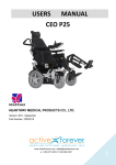
The ATPC-X42 All-Terrain Power Chair
Team 2: Niaz Khan, Selome Mandefro, Alex Mann, Vikram Shenoy
Team 2
Annalee Hughes, Susan Lucek, NSF Projects
Tolland, CT; (860)-872-7000
Important Safety Instructions
THOROUGHLY READ ALL WARNINGS BEFORE USING THIS CHAIR. IF YOU
FAIL TO DO SO A FALL, TIP-OVER OR LOSS OF CONTROL MAY OCCUR AND
CAUSE SEVERE INJURY TO YOU OR OTHERS
Take time learning to use the chair comfortably before taking it on difficult terrain
The decision to allow a user to ride the ATPC-X42 must be done with the permission of a
directly supervising adult. The directly supervising adult should read and follow all of the
contents of the owner’s manual before making this decision.
This product is meant for outdoor use only.
It must never be ridden in any area that could potentially do harm to humans, animals or
property.
The ATPC-X42 is intended for riders over the age of ten and under 175 pounds. Any
rider who does not comfortably fit in the vehicle and/or cannot comfortably use the
controls should not ride the ATPC-X42.
When seated in the wheelchair and not moving, always turn off the power to avoid
accidents
The ATPC-X42 should not be ridden indoors. Indoor flooring and carpets can be
damaged from contact with the tires as they are much larger than average power chair
wheels, and can easily carry dirt in from the outdoors.
The ATPC-X42 is designed to run on off-road surfaces. Grass, packed dirt, and moderate
off-road terrain are ideal riding surfaces.
The ATPC-X42 is not designed to pull or tow anything behind it as it may result in
damage to the chair or passenger, and may increase the risk of tipping the chair
backwards.
The ATPC-X42 can be used on wet surfaces such as mud or small puddles. HOWEVER,
never immerse any part of the ATPC-X42 in water or use the chair while it is raining.
Moisture can cause electrical malfunction or detrimental rust.
Always use the seat belt and four point harness that the electric wheelchair is equipped
with. The belt works the same way as an automobile seat belt and helps protect from falls
and related injuries
1
Heed the warning of the tilt alarm and avoid steep inclines when possible, though the
chair has been built to withstand tougher terrain, there is always a risk of tipping the chair
on too steep of a hill.
When going up or down a hill, travel directly up the natural slope of the hill, avoid going
up the hill on a slant as this increases the risk of tilting the chair sideways
Whenever possible, avoid venturing onto a busy street or cross walk. While a power
wheel chair offers greater mobility, it is not very quick and could leave you stuck in the
middle of a street during a light change
If you want to get on a sidewalk, look for curb cuts or a driveway to do so.
Exercise caution around young children who may want to reach for the control unit,
causing the the power chair to suddenly move.
If you are planning to traverse a path or trail, make sure that the path is clear of debris
and large rocks.
2
Parts and Accessories
Casters and Front Wheels
Footrest
3
Motors
Wheel Hubs
4
Rear Wheels
5
Chassis
Seat Mount with One-Inch Spacers
6
Actuator
7
Batteries
Anti-Tip Wheels
8
Seat
Back Mount and Headrest with Attachment
9
Armrests
Joystick
10
Joystick Hinge
11
12
Controller
Actuator Control Box
13
Circuitry
14
Chassis Tilt Sensor
Seat Belt
15
Safety Harness
Suspension
16
17
Features of the ATPC-X42 All-Terrain Power Chair
Automatic actuation while traveling downhill
Manual actuation also available
Tilt sensing alarm when chair is on a dangerous/steep grade
Large, tubeless treaded front and rear tires for improved traction and operation on rough
terrain
Joystick swing arm for easier entry and exit from chair
Joystick control with variable settings
Rotating foot rest for easier entry and exit from chair
Two deep cycle batteries for a full day's operation
Seat belt and harness for security and safety
Contoured seat to prevent side-to-side jostling during operation
Modular structure for seat attachment to allow adjustments as Annalee grows
Shock-absorbing suspension system
18
Table of Contents
Important Safety Instructions ..................................................................
Parts and Accessories ..............................................................................
Features of the ATPC-X42 .....................................................................
1.
Introduction ....................................................................................
1.1
Overview ..........................................................................................................
1.2
Step-By-Step ....................................................................................................
2.
Maintenance ...................................................................................
3.
Technical Description.....................................................................
4.
Troubleshooting..............................................................................
19
1. Introduction
1.1 Chair Overview
The ATPC-X42 All-Terrain Power Chair is a device consisting of several parts, and this section
will describe how all of the parts are assembled together. Certain parts make up assemblies, and
these assemblies are then put together to make up the entire power chair.
Seat Assembly
The seat assembly is comprised of the headrest, headrest attachment, aluminum seat case,
seat back cushion, back mount cross bar and back mount side rails, safety harness, and seat belt.
The headrest pole sits inside the through hole of the headrest attachment and the pin on the
headrest collar sits inside the bore on the headrest attachment.
The headrest attachment is connected to the aluminum seat case via four long, threaded
screws that prevent excess torque on one screw and hold it in place securely.
The back mount side rails are connected to the plastic seat case via hooks that came with
the seat, through which holes have been drilled. Screws go through the hooks that are on the seat
20
case, and screw into dove tails that reside in the dove tail tracks of the back mount side rails.
They are also connected at a second point via an extending piece of aluminum that wraps around
the bar coming out of the seat and screws into the dove tails of the side rails.
The back mount cross bar is connected to the side rails via screws that go through the two
holes on either side of the cross bar and into dove tails in the side rails. The harness and seat belt
are also attached to the side rails in this manner.
21
The back cushion is attached to the plastic seat case by velcro that lines a large area of
both pieces.
The backrest angle can be adjusted by removing the securing bolt at the bottom of the
support bar hinge plate. The angle can be adjusted by changing the hole that the bolt screws
through. Each hole is separated by a 4º increment
Seat Mount Assembly
The seat mount assembly is comprised of the seat mount side rails, two cross bars, a cross
bar connector, four one-inch spacers, dove tails, armrests, and attachment sites for the seat
assembly, and the seat base plate and seat cushion. There are dove tail tracks on the inside of the
seat mount side rails into which the one-inch spacers screw into dove tails that are inside the
tracks. Each spacer has two holes, with one hole being for one screw.
The front cross bar resides between the front two spacers and the rear cross bar resides
between the back two spacers. They are held in place by the same screws that hold the spacers
tightly. The cross bar connector is screwed into two holes in each cross bar and gives the overall
seat mount assembly stability.
The outside of the side rails also have dove tail tracks that allow the armrest connectors
and seat assembly connectors to be attached. The armrests sit inside these armrest connectors
and lock in place via pins.
22
To the right armrest, there is a bar attached, and the actuation control box is screwed to
this bar. The end of this bar is then connected to a shorter bar to which the joystick is held.
These two bars are held together by a piece of aluminum above and below the bar that is screwed
in. The bars are far enough apart to allow 90º rotation of the front bar, thereby forming a hinge.
23
The seat base plate also sits on the side rails and is secured by six screws. On top of the
seat base plate is Velcro to which the seat cushion is attached.
Chassis Assembly
The chassis is the body of the chair, constructed from aluminum, and was reused from the
Quickie S626 that this chair was built from. The chassis has attachment sites for the battery
cage, front casters, actuation circuit, motors, actuation support, and the sliding tracks so the seat
can actuate. The battery cage attaches to the underside of the carriage by 5 bolts per side, and
also to the bottom bar of the chassis by two bolts in the back. Batteries can be slid in to the box
and secured using the latches on the sides of the cage.
The front caster axles are attached by bolts through the front holes in the chassis. In these
axle holes are two bearings, one each on the top and bottom of a spacer. A stepped washer is
then placed on top of the upper bearing to provide a proper contact point to the nut which secures
the caster in place.
24
The actuation circuit is attached to a bracket on the front bottom of the chassis and is
secured by Velcro.
The motor mounts are attached by large bolts into the tube at the bottom of the chassis, and
are also secured on by the shocks which attach to the top of the motor mount and connect to the
underside of the upper chassis by a bolt. The motors are attached to the motor mounts by four
bolts on the bottom of the mount cage.
The crossbar which supports the actuator attaches underneath the front drop arms of the
chassis near where the casters attach. Two bolts connect the bar on each side.
The tracks which house sliding bars that mount the seat assembly are also attached to the
chassis, and are secured by five bolts on the inside plates present in the chassis on the right and
left sides.
Undercarriage Assembly
The undercarriage is where the actuator connects to the rest of the chair, and where the
circuitry is housed. The braking mechanisms for the anti-tip wheels are also connected to this
part of the chair.
A plate is mounted on top of the two siding bars on the tracks, which allows the linear
actuator to push against and translate into tilt. Two bolts on each bar connect the plate.
25
The linear actuator is bolted through the crossbar on the front of the chassis to hold it in
place, and the push bar connects to the plate on the sliding bars through a bolt through the bar.
The crossbar also has two hinged attachments to connect to the rear crossbar on the seat
assembly. This is secured by two bolts on each side.
Two stiff round bars connect the front crossbar mounting the actuator to the seat assembly,
and will keep the assembly at a set distance so that the seat is forced to tilt.
The brake mechanisms for the rear tilt wheels prevent the wheels from flexing if the chair
is tilted too far back. These attach to the stoppers on the front cross bars with two bolts, and
when they are compressed, they lock up the tilt wheels.
Rear Wheel Assembly
The rear wheels are attached to the motors by custom made wheel hubs. The hubs have
holes that align with the rear wheels. Bolts were welded to the inside face of the hubs, and lug
26
nuts were screwed on tightly to the outside face of the wheel. The hub also has a key way that
aligns with the one on the motor axle, and a counter bore allows a nut to be put on the thread at
the end of the motor axle.
Front Wheels and Casters Assembly
The casters are made of three pieces of aluminum which are screwed together, and a bolt,
which gets locked into the chassis by a nut. There are two angular pieces of aluminum with two
threaded holes in each top, and a rectangular piece with four holes to bridge the two angular
pieces. Cap screws secure these pieces together.
27
There is also a hole at the bottom of each angular piece, one of which is threaded, to allow
a bolt to pass through one side, go through the front wheel, and screw into the other side. This
attaches the tire to the caster. Between the inside face of the caster and the tire there is also a
caster spacer that helps prevent the tire from sliding along the bolt.
Footrest Assembly
The footrest attaches to the seat frame of the chair by a plug and locking swing arm. The
lever on the footrest can be depressed to allow the rest to swing out of the user’s way. This lever
is connected in the footrest to a spring loaded screw which pulls it back into the locked position.
The footrest mount is connected to the bar by two press buttons which secure into the mount, and
allow for the length of the footrest to be adjusted. The footplate is attached to the footrest by
four screws through the ankle restraints.
28
1.2 Step-By-Step Instructions
Check to make sure the tires are properly inflated, the motors are engaged, and the
batteries are charged before use.
29
Once passenger enters chair, secure them with the seat belt, four point harness, and foot
restraints. Each has buckles to ensure security within the device.
To turn the power chair on, press down on the toggle switch on the joystick.
Activate the tilt sensor by toggling the switch labeled tilt sensor to the right.
30
Activate automatic actuation by toggling the switch labeled Auto-Actuate to the right.
To manually adjust actuation, disable Auto-Actuate and press the forward-most blue
button to lean the chair back (actuate upwards), and the rear blue button to lean the chair
forward (actuate downwards).
Adjust the speed by turning the speed control knob on the joystick.
31
Push the joystick forward to move the chair forward. These controls work for side to side
and reverse as well.
The joystick is pressure sensitive, so it can be pressed lightly in order to go slower.
Turn off the chair when done using by pressing the toggle switch on the joystick down.
32
2. Maintenance
Casters and Front Wheels
o Remove casters from chassis every few months and grease the axle in the
chassis to prevent rust and physical degradation caused by friction.
o If the casters are wobbling make sure to tighten them.
Motors
o Avoid self maintenance on the motors when possible, take them into a licensed
mechanic if they are in need of a tune up
o Remove the hubs from the motors every few months to grease the axles to prevent
rust and physical degradation caused by friction
Wheel Hubs
o Clean the hubs often to prevent rust
o Make sure lug nuts are always tight before use
Rear Wheels
o Check the tire pressure before operating to ensure a safe pressure and guarantee
traction
Chassis
o Check the chassis for rust and ensure all connections are tight
o Clean the chassis and the rest of the chair of mud and dirt to prevent rust
Batteries
o Recharge batteries daily
o Check batteries for corrosion often
o Battery Corrosion:
1. Check battery terminals often for corrosion.
2. If corrosion is present, use a wire brush to clean the terminals
3. NOTE– Always wear safety glasses and rubber gloves.
4. Use baking soda to neutralize acid.
5. Use petroleum jelly to re-grease the terminals after connecting cable to
battery. (Completely cover the terminal nut and bolt, cable clip and any
exposed cable with jelly).
Seat
o Adjust seat to ensure proper poster and comfort of user as they grow
Back Mount
o Periodically check mounting bolts for tightness
Headrest with Attachment
o Adjust headrest often to make sure it is providing the user with a comfortable and
proper posture
Joystick Hinge
o Tighten bolts on joystick hinge to ensure enough resistance from swinging
without too much so that it can not be moved. This is especially important on the
front bolt.
Controller
o Make sure controller is clear of water at all times and that all cables are securely
connected. If looking at the controller ports, M1 represents the right motor and
33
M2 is the left motor. The connection to the left of M1 is the actuator controller.
The connection to the right of M2 is the joystick controller. The connection in the
middle is the connection from the batteries.
Circuitry
o The circuitry in the ATPC involves the auto actuation circuit. Keep the unit dry in
order to prevent shorting the circuit. If the programming ever needs to be set for
any reason, the PIC may be removed and programmed however it is not advised
to do so. The controller box should also not be removed as it has been calibrated.
Calibration includes reading the voltage from the sensors and making sure they
are aligned to zero degrees. The voltage that is on pin 2 and 3 on the PIC should
read approximately 1.5 volts. These voltages are read from the two sensors and
are the voltage value when the chair is level. Pins 1,11,and 32 should have a value
of 5 volts. If the voltages on the pins stated above are correct then the circuit is
operating normal. Below is the main function that PIC has been installed with.
o void ADConvert(void)
{
unsigned short seat=0;
unsigned short chair=0;
CHS1 = 0;
CHS0 = 1;
// Use channel AN1
ADON = 1;
// Turn A/D on
__delay_us(30); // delay 30 usec to settle A/D acquisition
ADGO = 1;
// Start conversion
while ( ADGO ); // wait for ADGO to go off signalling end of conversion
seat=ADRESH*4+ADRESL/64;
CHS1 = 0;
CHS0 = 0;
// Use channel AN0
ADON = 1;
// Turn A/D on
__delay_us(30); // delay 30 usec to settle A/D acquisition
ADGO = 1;
// Start conversion
while ( ADGO ); // wait for ADGO to go off signalling end of conversion
chair=ADRESH*4+ADRESL/64;
if(chair>308) // if chair is going up
{
if(seat-chair>2)
{
RD7=0; //no up
for(i=1;i<6;i++)
{
__delay_us(100);
}
34
RD6=1; //down to make even
}
else
{
RD7=0;
RD6=0; //nothing should move
}
}
if(chair<306) // if chair is going down
{
if(seat<307)
{
RD6 = 0; //down = off
for(i=1;i<6;i++)
{
__delay_us(100);
}
RD7 = 1; //up = on
}
else if(seat>308)
{
RD7 = 0; //up = off
for(i=1;i<6;i++)
{
__delay_us(100);
}
RD6 = 1; //down = on
}
else
{
RD6=0;
RD7=0;
}
}
if(chair<295) //~10degrees
RD5 = 1; // buzzer at threshold
if(chair>295)
RD5 = 0; //no buzzer
}
Chassis Sensor
o The sensor is installed within a PVC case under the seat. The case is not
waterproof thus prevent water from entering the underside of the chair.
Seat Belt
35
o
If seat belt begins to fray, replace it immediately as this can become unreliable
and not guarantee the safe restraint of the passenger
Safety Harness
o If the safety harness begins to fray, replace it immediately as this can become
unreliable and not guarantee the safe restraint of the passenger
Suspension
o The ATPC is equipped with the Rock Shox supension system. It provides
dampening during travel especially during off road driving. If the dampening
needs to be changed it can be adjusted by turning the red adjustment knob located
at the top of the spring. Turning clockwise will reduce the dampening while
turning counter clockwise will decrease dampening. Too much rebound will cause
stiff riding conditions while too little rebound will cause too much bouncing.
Paint
o If paint has chipped off, the original paint color used was Rustoleum Metallic
Blue spraypaint, or Rustoleum Matte Black spraypaint
36
3. Technical Description
This section describes exactly how each subunit operates and explains items to you, the operator
of this device, which should be of note before, during, and after using the chair.
Automatic actuation while traveling downhill
The automatic actuation is an extra addition to your chair. It allows the user to always be
level during all operation, by controlling the linear actuator that adjusts seat tilt. The unit has two
switches that control the power to the circuit which will keep track of tilt and will sound the
buzzer when the user is on a steep grade. The second switch on the unit controls automatic
actuation. When both switches are turned on, the chair will automatically level the seat
depending on the hill it is on. If the user does not want the constant actuation, then it is
recommended to turn the system off by moving the switches to the left, which is the off position.
The switches are connected to AXDL 330 accelerometers, one of which resides in the control
box, the other on the chassis, and they obtain input from the grade of the slope upon which the
chair is being driven. The varying angles they are subject to change the output voltage and
inputs that to a PIC16F874 microcontroller, which in turn makes the chair actuate upward and
downward relative to the corresponding changes in voltage.
Manual actuation also available
The user can manually adjust the seat at this time with the manual actuation switch,
which are the blue buttons labeled up and down on the control box. If the user does not wish to
use the automatic actuation circuit and would rather use the manual actuation the user may.
However this can only be done when the auto actuation circuit is turned off, and thus the "autoactuation" switch should be moved to the left. In the event of turning off the auto-actuation, the
accelerometers do not turn over the voltages to the microcontroller; however the manual
actuation still works perfectly. Otherwise the actuation will still compensate back to level with
the ground. The actuator can actuate upwards as much as 45 degrees and downwards until the
seat is level with flat ground. If going uphill, the actuator does not have the ability to go beyond
0 degrees relative to flat ground.
37
Tilt sensing alarm when chair is on a dangerous/steep grade
Also part of the automatic actuation unit is a buzzer that sounds when the user
approaches a hill that is not safe. If a hill is greater than 10 degrees it is not recommended to go
down that hill. A buzzer is attached to the outside of the actuation box and will sound loudly
when going to a hill that is not safe. The user may still choose to go down the hill but it is not
recommended. Also keep in mind that the buzzer will constantly sound if the user is still on the
steep grade. If the buzzer becomes an irritant to the user, she may turn the automatic actuation
circuit off, however it is her responsibility to keep to safe grades and take it slow when she
drives down a slope.
Large, tubeless treaded front and rear tires for improved traction and operation on rough terrain
The ATPC has been fitted with larger off road tires, with larger treads rather than the
conventional tires used in normal power chairs. The rear tires have an outer diameter of 16
inches and a width of 4.5 inches. The front tires have an outer diameter of 10.5 inches and a
width of 3.5 inches. These larger tires will allow smaller obstacles to be cleared and the treading
will allow operation on a variety of terrains, including grass and dirt. The front tires are attached
to the chair via custom made casters that are 4.5 inches wide to accommodate the wide front
wheels with room that allows them to spin. The casters are made of 1/2-inch thick aluminum
that allows them to be durable and have the same angle of descent from the chair as the previous
casters, which is 18 degrees. The rear wheels are attached to the motors by custom-made steel
hubs that have the complementary key way to that on the motor, and welded bolts are screwed
through the holes in the wheel into lug nuts on the outside of the wheel. Finally, everything is
locked in place by a nut that is secured on the thread at the end of the motor axle.
Joystick control with variable settings
There is a switch on the joystick control that turns the power chair on, and this switch
also functions as the off switch and kill switch. It is located on the lower right side of the
joystick and works by simply pushing the switch down. The joystick has a variable speed
control knob to the left of the on/off switch that has been set so that the slow speed can be used
for in the house the driving if the operator desires. The acceleration and top speed is a minimum
38
to limit the collisions that can occur if she was going fast. The maximum speed on the controller
is the speed that has been set for outdoor use. It has a faster driving speed and will be able to
conquer any terrain. The maximum speed, however, should only be used in the yard and not
anywhere else. If the user wishes to take the chair to the streets and pavements, it is not
recommended to drive at maximum speed. Instead, switching to half speed is more appropriate.
If for some reason the chair is not as responsive as the user desires, the chair can be
reprogrammed. The user will need to obtain a Qtronix Programmer, which interfaces with the
joystick. The GUI that is in the programmer is a simple menu that allows for full manipulation of
the chair from speed to acceleration.
Rotating foot rest for easier entry and exit from chair
For easy access into and out of the ATPC, the footrest is able to swing out of the way.
The foot rest has a release mechanism on the side of the chair. When pressed, the footrest will
easily swing away from the front of the chair and to the right. The footrest can then be pushed
back to the left when the operator is completely situated in the chair or removed from the chair,
and it will lock back into place. The footrest is attached to the side rails of the seat mount, and
the operator should take care to not remove their feet from the ankle restraints, as they can get hit
by the moving casters or front wheels. The ankle restraints fit around the back of the heel and
buckle in place around the top of the foot.
Joystick swing arm for easier entry and exit from chair
For easy access into and out of the ATPC, the joystick is able to swing out of the way.
The joystick can be pushed to the right and out of the way so that the user may be able to get a
firmer grip on the end of the arm rest to push them out of the chair. The joystick can then be
moved back to its original position by pushing the joystick back to the left. It can be moved 90degrees to the right of the normal position, and back 90-degrees to the normal position for device
operation.
Two deep cycle batteries for a full day's operation
39
The ATPC has been equipped with two 12V 75Ahr, PowerSonic batteries. The batteries
are deep cycle Gel Cells. They provide the chair with all day operation and are capable of
recharging. The batteries are recharged by attaching the charge inverter to the plug-in site
located on the joystick controller. The amount of charge left on a battery life cycle is seen on the
red-yellow-green scale, where green bars denote most of the charge is left, while if only red bars
are seen, the batteries need to be recharged before operating the chair again.
Chair manually portable if batteries die and charger not accessible
The chair can be moved even if the batteries have drained completely. Normally the
motors are engaged for operation via the joystick controller, and when these are engaged, the
chair cannot be manually pushed. However, the motors can be disengaged via levers attached to
the underside of the motors. If pulled outward, the motors will disengage and the chair can be
physically be pushed by applying forward force to the handles on either side of the seat. Make
sure the motors are engaged again upon returning to the charger because the chair cannot operate
electrically without the motors being engaged.
Seat belt and harness for security and safety
While using the chair in an off road setting it is important for the user to be secure within
the chair. Therefore the ATPC is equipped with both a standard seat belt around the hips as well
as a harness that crosses the chest and attaches in four locations around the chair mount. While
using the chair off road it is essential that all harnesses be attached. Each of the four points on
the harness has a buckle that will secure the operator to the seat, and the seat belt also operates
via a buckle mechanism.
Headrest attachment necessary to prevent injury and for comfort
Also it is important that the chair have the head rest attached to the chair so as to prevent
whiplash. The headrest contains two collars that allow vertical and horizontal adjustment based
on how tall the operator is and where their head is located. The collar on the vertical bar can be
unscrewed and moved up to lower the headrest or down to raise the location of the headrest. If
40
the collar on the horizontal bar is loosened, then the headrest can be moved forward or backward
to assure the comfort of the operator.
Contoured seat to prevent side-to-side jostling during operation
The ATPC has been equipped with the JAY2 Contoured Seat Back. This seat back
provides the user with support and also is able to cradle the user from the sides to prevent sideto-side movement. The side contour is modular and pieces are able to be attached and taken off
as the user grows in order to provide more or less contour. If further security is necessary, then
there is Velcro located on the inside of the plastic seat structure to which foam padding can be
added, thereby moving the wings of the seat cushion more to the center-line of the power chair.
The modular structure for seat attachment is designed to allow adjustments as Annalee
grows. The points of seat attachment can be moved up and down along the tracks of the dove
tails, thus moving the whole seat up and down. Also, the seat belt and harness are attached to
dove tails and can be moved up and down the tracks in order to be situated in the proper
location. For example, if the harness is too tight, then the screws holding the harness to the dove
tails can be loosened and the harness can be moved up, thereby allowing more slack in the
harness. The same can be done for the seat belt, if the seat belt is loosened all the way but is still
too tight. Keep in mind that if one item needs to be shifted up and down, it may require other
items to be moved as well in order to accommodate the change since multiple items are screwed
into the dove tail tracks of the back mount.
41
4. Troubleshooting
The chair won't start
Ensure that all of the cables are connected to the controller on the front of the chair
Ensure that the batteries are connected and charged
Check the connection to the joystick
The chair won't move:
Make sure the motors are engaged and connected to the controller
The seat belt and/or harness are too tight to use
Loosen straps to point of seat belt and/or harness fitting snugly but comfortably.
If still too tight, unscrew seat belt and/or harness from the dove tail tracks on the back of
the seat back mount and side the dove tails upward to provide extra slack to the seat belt
and/or harness.
The chair won't actuate manually:
Check the connections to the controller. The actuator switch should be connected to the
actuator controller in the dual switch port. Make sure the color coded connections to the
linear actuator are also made. There are two connections from the actuator to the
controller. Also make sure the actuator controller is connected to the P&G drive
controller. Without this connection the vehicle will not move.
Ensure that actuation is set to manual. If the actuation is on automatic, the system may
not allow you to start manual actuation.
Make sure the batteries are charged
The chair won't actuate automatically:
Check to see that the switch for auto actuation is on and so is the switch for tilt on the
actuation control box.
Ensure that the manual actuation buttons are not being pressed. Automatic and manual
actuation can not occur at the same time.
42
The batteries may need replacing. Replace with fresh 9V batteries.
The tilt sensor wont sound the alarm:
Ensure that you are in an unsafe position. The sensor will only sound after hitting the
critical angle.
Ensure that the tilt switch is on.
The batteries may need replacing. Replace with fresh 9V batteries.
Drive Wheel Flat Tire:
Elevate and securely support chair so that wheel is off the ground.
Remove the four lug nuts securing wheel to hub
Refill the tire with air
Immerse the tire in water to find out where the air leak is
If the leak is coming from the edge of the rim and tire, apply a sealant.
If the leak is coming from the valve follow the instructions below.
o Pry the tire off of the wheel
o Pull out the damaged valve
o Replace with a new valve
o Realign the tire to the wheel and refill with air
Place the wheel back on the hub and secure the lug nuts
The Quickie S626 User Manual may also be found online and used for reference when
troubleshooting the chair or questions on maintenance are had.
43