1
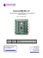
Emerald-MM-8EL-XT
PCI/104-Express 4- or 8-Port Multi-Protocol Serial Port Module
With Opto-isolation
Rev A.01 November 2014
Revision
Date
A.00
8/21/2014
Initial release
A.01
11/20/14
Minor update to pin out
FOR TECHNICAL SUPPORT
PLEASE CONTACT:
[email protected]
Comment
Copyright 2014
Diamond Systems Corporation
555 Ellis Street
Mountain View, CA 94043 USA
Tel 1-650-810-2500
Fax 1-650-810-2525
www.diamondsystems.com
CONTENTS
1.
2.
Important Safe Handling Information .............................................................................................................3
Introduction .......................................................................................................................................................4
2.1 Description .....................................................................................................................................................4
2.2 Models ...........................................................................................................................................................5
2.3 Functional Block Diagram ..............................................................................................................................5
2.4 Board Layout .................................................................................................................................................6
2.5 Connector Summary ......................................................................................................................................6
3. Connectors ........................................................................................................................................................7
3.1 Serial Ports 1-8 (Port 1-8) ..............................................................................................................................7
3.2 Data Acquisition (DAQ) .................................................................................................................................7
3.3 PCI-104 Bus ..................................................................................................................................................8
3.4 PCIe/104 Bus.................................................................................................................................................8
4. Key Subsystems ...............................................................................................................................................9
4.1 UART .............................................................................................................................................................9
4.2 Serial Protocol Transceivers ..........................................................................................................................9
4.3 Isolation .........................................................................................................................................................9
4.4 Microcontroller ...............................................................................................................................................9
4.5 Host Bus Interface ...................................................................................................................................... 10
4.6 Power Supply.............................................................................................................................................. 10
5. Console Configuration .................................................................................................................................. 10
5.1 Software Functions ..................................................................................................................................... 11
5.2 Configuration File........................................................................................................................................ 14
6. GUI Console Configuration ........................................................................................................................... 15
7. Software Driver .............................................................................................................................................. 16
8. Specifications................................................................................................................................................. 17
EMM-8EL-XT User Manual Rev A.01
www.diamondsystems.com
Page 2
1. IMPORTANT SAFE HANDLING INFORMATION
WARNING!
ESD-Sensitive Electronic Equipment
Observe ESD-safe handling procedures when working with this product.
Always use this product in a properly grounded work area and wear appropriate
ESD-preventive clothing and/or accessories.
Always store this product in ESD-protective packaging when not in use.
Safe Handling Precautions
This board contains a high density connector with many connections to sensitive electronic components. This
creates many opportunities for accidental damage during handling, installation and connection to other
equipment. The list here describes common causes of failure found on boards returned to Diamond Systems for
repair. This information is provided as a source of advice to help you prevent damaging your Diamond (or any
vendor’s) embedded computer boards.
ESD damage – This type of damage is usually almost impossible to detect, because there is no visual sign of
failure or damage. The symptom is that the board eventually simply stops working, because some component
becomes defective. Usually the failure can be identified and the chip can be replaced. To prevent ESD damage,
always follow proper ESD-prevention practices when handling computer boards.
Damage during handling or storage – On some boards we have noticed physical damage from mishandling. A
common observation is that a screwdriver slipped while installing the board, causing a gouge in the PCB surface
and cutting signal traces or damaging components.
Another common observation is damaged board corners, indicating the board was dropped. This may or may not
cause damage to the circuitry, depending on what is near the corner. Most of our boards are designed with at
least 25 mils clearance between the board edge and any component pad, and ground / power planes are at least
20 mils from the edge to avoid possible shorting from this type of damage. However these design rules are not
sufficient to prevent damage in all situations.
A third cause of failure is when a metal screwdriver tip slips, or a screw drops onto the board while it is powered
on, causing a short between a power pin and a signal pin on a component. This can cause overvoltage / power
supply problems described below. To avoid this type of failure, only perform assembly operations when the
system is powered off.
Sometimes boards are stored in racks with slots that grip the edge of the board. This is a common practice for
board manufacturers. However our boards are generally very dense, and if the board has components very close
to the board edge, they can be damaged or even knocked off the board when the board tilts back in the rack.
Diamond recommends that all our boards be stored only in individual ESD-safe packaging. If multiple boards are
stored together, they should be contained in bins with dividers between boards. Do not pile boards on top of each
other or cram too many boards into a small location. This can cause damage to connector pins or fragile
components.
Power supply wired backwards – Our power supplies and boards are not designed to withstand a reverse
power supply connection. This will destroy each IC that is connected to the power supply (i.e. almost all ICs). In
this case the board will most likely will be unrepairable and must be replaced. A chip destroyed by reverse power
or by excessive power will often have a visible hole on the top or show some deformation on the top surface due
to vaporization inside the package. Check twice before applying power!
Overvoltage on digital I/O line – If a digital I/O signal is connected to a voltage above the maximum specified
voltage, the digital circuitry can be damaged. On most of our boards the acceptable range of voltages connected
to digital I/O signals is 0-5V, and they can withstand about 0.5V beyond that (-0.5 to 5.5V) before being damaged.
However logic signals at 12V and even 24V are common, and if one of these is connected to a 5V logic chip, the
chip will be damaged, and the damage could even extend past that chip to others in the circuit
EMM-8EL-XT User Manual Rev A.01
www.diamondsystems.com
Page 3
2. INTRODUCTION
2.1
Description
The Emerald-MM-8EL-XT is a family of PCIe/104 OneBank serial cards offering 4 or 8 serial ports with or without
opto-isolation. The module is based on a high speed UART with 256-byte TX/RX FIFOs and auto RS-485
transmit control. The EMM-8EL-XT fits a wide variety of embedded serial I/O application needs.
Each port is independently isolated with an ADUM5402 isolated power + signal chip plus additional isolators for
control signals. All features are programmable, including protocol and RS-485 line termination. An onboard
microcontroller interfaces to the GPIO pins on the UART and provides control of the configuration options. The
microcontroller also manages staggered turn-on of the ADUM5402 devices to limit power-on inrush current. All
configurations are stored in the microcontroller’s flash memory and are automatically reloaded on power-up. The
board is in the PCI/104-Express form factor with the PCIe/104 one bank bus connector for cost reduction.
Functions
8 or 4 RS-232/422/485 serial ports with programmable protocol
Data rates:
RS-232 mode up to 1Mbps
RS-422/485 modes up to 10Mbps
XR17V358/XR17V354 PCIe interface UART with 256-byte FIFOs
Models available with or without opto-isolation
SP336 multi-protocol transceivers with high speed, ESD, and open-circuit protection
RS-422/485 termination programmable
+/-15KV ESD protection on all serial ports
Independent 2500VRMS isolation port by port with individual I/O connectors for each port
Staggered turn-on of isolated power devices for reduced power-on inrush current
8 digital I/O or analog input lines
TM
PCIex1 host interface using PCIe/104 “OneBank ” connector
Onboard microcontroller to manage all configuration options with flash memory for configuration
storage and automatic recall
Latching connectors for increase ruggedness
Comprehensive software suite enables easy configuration and control
Operating System Support
Linux 2.6.16, 2.6.27, 2.6.31, and 2.6.32
Windows XP & 2000
Windows Vista and 7
Mechanical, Electrical, Environmental
PCI/104-Express form factor 3.55” x 3.775”
-40°C to +85°C ambient operating temperature
MIL-STD-202G shock and vibration compatible
Power input: +5VDC +/- 5%
EMM-8EL-XT User Manual Rev A.01
www.diamondsystems.com
Page 4
2.2
Models
The following Emerald-MM-8EL-XT models and cable kits are available.
# of Ports
Isolation
Cable Kits
Description
EMM-8EL-XT
8
Yes
CK-EMM-8EL
8 serial cables, 1 digital/analog cable
EMM-4EL-XT
4
Yes
CK-EMM-4EL
4 serial cables, 1 digital/analog cable
EMM-8E-XT
8
No
EMM-4E-XT
4
No
Model
2.3
Functional Block Diagram
The Emerald-MM-8EL-XT block diagram is shown below.
EMM-8EL-XT User Manual Rev A.01
www.diamondsystems.com
Page 5
2.4
Board Layout
The Emerald-MM-8EL-XT connector locations are shown below.
PCI-104
DAQ
Port 5
Port 1
Port 6
Port 2
Port 7
Port 3
Port 8
Port 4
PCIe/104 one bank
2.5
Connector Summary
The following tables list the Emerald-MM-8EL-XT board connectors.
Connector
Description
Port 1-8
Serial ports 1-8 connectors
DAQ
Data acquisition connector
PCI-104
PCI-104 bus connector
PCIe/104
PCIe one bank bus connector
EMM-8EL-XT User Manual Rev A.01
www.diamondsystems.com
Page 6
3. CONNECTORS
This section describes the connectors on the Emerald-MM-8EL-XT module.
3.1
Serial Ports 1-8 (Port 1-8)
The 4 or 8 serial ports are provided on miniature 10-pin headers with 1 port per header. Ports 1-4 are located on
the right side of the board, and ports 5-8, if installed, are located on the left. The pin definition depends on the
serial protocol selected. All ports have identical pinouts as shown below.
RS-232 Configuration:
NC
TXD
RXD
NC
1
3
5
7
2
4
6
8
NC
RTS
CTS
Iso Gnd
1
3
5
7
2
4
6
8
NC
TX+
RXIso Gnd
1
3
5
7
2
4
6
8
NC
Data +
NC
Iso Gnd
RS-422 Configuration:
NC
TXRX+
NC
RS-485 Configuration:
NC
Data NC
NC
Connector Part Number / Description
JST S08B-PUDSS-1 2x4 2mm pitch through hole right angle locking pin header, standard
3.2
Data Acquisition (DAQ)
Eight GPIO signals from the microcontroller are made available on a 10 pin header for auxiliary GPIO / A/D
functions. All the A/D capable pins are grouped together at the top of the connector near the analog ground pin.
A Gnd
GPIO1 / A/D1
GPIO3 / A/D3
GPIO5 / A/D5
GPIO7
1
3
5
7
9
2
4
6
8
10
GPIO0 / A/D0
GPIO2 / A/D2
GPIO4 / A/D4
GPIO6 / A/D6
D Gnd
Connector Part Number / Description
2x5 2mm pitch through-hole connector with 4mm high posts and gold flash plating
EMM-8EL-XT User Manual Rev A.01
www.diamondsystems.com
Page 7
3.3
PCI-104 Bus
The PCI-104 (PCI) bus connector is provided on the top side to enable the mounting of additional I/O boards. The
PCI connector is non-stack through (top side only) and is located in the standard PCI-104 location. Its pinout is
as defined in the PC/104-Plus specification available on www.pc104.org. The VIO pins are jumper-selected and
are protected with a polyswitch resettable fuse.
3.4
PCIe/104 Bus
The PCIe/104 connector follows the PCIe/104-Express standard. This one bank connector is connector A with
the following pin out.
USB-OC+3.3V
USB 5+
USB 5Gnd
PCIe 4 T+
PCIe 4 TGnd
Gnd
PCIe 1 R+
PCIe 1 RGnd
Gnd
PCIe 4 Clk+
PCIe 4 Clk+5V_SB
Gnd
SMB Data
SMB Clk
SMB Alert-
1
3
5
7
9
11
13
15
17
19
21
23
25
27
29
31
33
35
37
39
41
43
45
47
49
51
EMM-8EL-XT User Manual Rev A.01
+
5
V
T
A
B
2
4
6
8
10
12
14
16
18
20
22
24
26
28
30
32
34
36
38
40
42
44
46
48
50
52
PCIe Reset+3.3V
USB 6+
USB 6Gnd
PCIe 1 T+
PCIe 1 TGnd
Gnd
PCIe 0 R+
PCIe 0 RGnd
Gnd
PCIe 1 Clk+
PCIe 1 Clk+5V_SB
www.diamondsystems.com
Page 8
4. KEY SUBSYSTEMS
4.1
UART
The UART is the Exar XR17V358/XR17V354 octal/quad UART with PCIe interface. These UARTs feature several
advanced features:
256-byte TX/RX FIFOs for better reliability and lower system overhead during high-speed transmission
Auto RS-485 transmit mode for compatibility with standard RS-232 drivers. This is accomplished by tying
the EN485- pin on the XR17V358/354 to ground.
High speed data rates: 1Mbps in RS-232, 10Mbps in RS-422 / RS-485
4.2
Serial Protocol Transceivers
The transceivers are SP336 with RS-232, RS-422, and RS-485 protocol capability. Each serial port uses its own
transceiver for opto-isolation purposes. Each port’s protocol is selected with 2 data lines from the onboard
microcontroller.
4.3
Isolation
Isolation is provided via several methods:
The serial port signals are isolated via an Analog Devices ADUM5402 power+signal device that provides
power for the isolated transceivers plus isolation of the TX, RX, RTS, and CTS signals. These isolator
devices exhibit significant inrush current on power-up, so they are powered up one by one with a
programmable delay between devices to limit peak inrush current to just one device instead of 4 or 8. The
power-on control is provided by an onboard microcontroller drivint a FET that switches the +5V supply to
the ADUM5402.
The two protocol configuration control signals are isolated via a separate dual opto-isolator.
The RS-485 121-ohm termination resistor is enabled via a photoMOS solid state relay with very low on
resistance. The SSR is controlled with a data line from the onboard microcontroller.
Isolation of serial port signals and protocol select signals can be bypassed with the installation of 0-ohm resistors.
The RS-485 termination isolator is required and cannot be eliminated.
4.4
Microcontroller
All configuration is done via an onboard microcontroller which interfaces to the host via a custom serial
interface using the UART’s GPIO lines. The microcontroller is configured using a series of registers that
provide control over the various options. The microcontroller contains built-in flash memory which is used
to store the configuration for automatic reload on power-up or reset. The microcontroller manages several
configuration features:
Serial port protocol: RS-232, RS-422, and RS-485, independently programmable port by port
RS-485 121-ohm termination resistor enable / disable
Turn-on timing of ADUM5402 isolated power devices
Board configuration readback (number of ports and isolation / non-isolation)
Programmable blue LED
Heartbeat to indicate circuit alive
Auxiliary data acquisition circuit on 10-pin I/O header with ESD protection
Application software is provided to communicate with the microcontroller and configure all features on the board.
EMM-8EL-XT User Manual Rev A.01
www.diamondsystems.com
Page 9
4.5
Host Bus Interface
The EMME series interfaces to the host SBC via a single PCIe x1 link on bank 1 of the PCIe/104 connector. The
module implements the PCIe/104-Express one bank connector and the board layout supports the installation of
the full-size 3-bank connector on the top and bottom sides. The PCIe lanes on the first bank are shifted according
to the requirements of PCIe/104, and a multiplexor selects lane 0 or lane 3 depending on whether the board is
installed above or below the host SBC. All signals on banks 2 and 3 are passed straight through between bottom
and top.
4.6
Power Supply
Power is obtained from the +5V tab on bank one of the PCIe/104 connector. The module generates all other
required voltages from the +5V input.
5. CONSOLE CONFIGURATION
The Emerald-MM-8EL-XT comes with software to manage and store configurations using the on-board
microcontroller. The PIC microcontroller is used to manage several functions on the board:
Serial interface to host for configuration and control
Controlled turn-on of isolated power supplies to limit inrush current
Serial protocol selection of the SP336 multiprotocol transceivers
121 ohm line termination for RS-422/485 protocols
Heartbeat to provide indication of device activity
LED control
Board configuration readback
GPIO / A/D signals on 10-pin I/O connector
The microcontroller interfaces to the host via eight GPIO pins on the Exar XR17V358 PCIe UART. Refer to the
XR17V358 datasheet for details on programming these registers. The registers must be configured for the correct
direction at the start of the program.
The program provides a text-based user interface that can be ported to Windows and Linux. It provides a menu of
options to configure and control the board. The program displays the menu and asks for a selection by number.
After the selection is made, the program jumps to the code to execute that function. After execution is complete,
the program returns to the main menu, and the sequence repeats.
EMM-8EL-XT User Manual Rev A.01
www.diamondsystems.com
Page 10
5.1
Software Functions
A command line interface (CLI) software program provides a
simple and direct method for configuring the Emerald-MM8EL. The main screen of the CLI program is shown at the
right.
Descriptions of the available CPI functions are provided
below.
Reset
When this command is selected, the program will drive the reset pin on the UART interface high, and then bring it
low. The PIC should undergo its reset sequence. The program waits for Ack to go low and reports an error if it
fails to go low within a given time interval.
Presence Detection
This feature confirms the PIC on the board is present and responding. When this command is selected, the
program will do the following:
1.
2.
3.
4.
5.
Check for Ack low.
Drive Sync high.
Check for Ack high.
Drive Sync low.
Check for Ack low.
If the sequence succeeds, the program reports board is present and responding, otherwise board is
unresponsive.
Configuration Readback
The program performs two steps:
1. It reads the configuration register and reports its value and interpretation.
00 = 4 ports, no isolation
01 = 4 ports, isolation
10 = 8 ports, no isolation
11 = 8 ports, isolation
2. The program reads the software revision at address 0x3F and reports its value.
ADUM5402 Enable Configuration
The user enters enable/disable selections for each of the 8 ports and presses OK. The host transmits the selected
configuration to the board’s power enable register.
ADUM5402 Turn-on Delay Configuration
The user enters values for the initial turn-on delay and the inter-port turn-on delay in milliseconds, and then
presses OK. The host transmits the selected configuration to the board’s turn-on delay and inter-port delay
registers (a total of 2 transmissions).
EMM-8EL-XT User Manual Rev A.01
www.diamondsystems.com
Page 11
LED Control
The user selects On or Off and presses OK. The host transmits the selected configuration to the board’s LED
register.
Protocol Select and Line Termination
The program sequences through all 8 ports one at a time, numbered 0-7. For each port, the user enters the
desired protocol. If the protocol is RS-422 or RS-485, the program asks for line termination enable/disable and the
user enters that option. Once all 8 port configurations are entered, the program transmits the configuration data to
the board in succession (a total of 8 transmissions).
GPIO Configuration
The user enters the direction configuration byte and direction byte. The program writes the two bytes to the board
in the configuration register and direction register.
GPIO Input
The program reads the 8 GPIO lines and returns their values. Only the bits which are set for digital input are valid.
GPIO Output
The user enters the desired output value in Hex. The program writes the value to the output register. Only the bits
which are set for digital input are valid.
Read/Write RAM/Flash register
The user selects RAM or Flash, address in Hex, and data in Hex if a write operation. The program executes the
given command. This command may be used to directly write to any valid RAM or Flash register. It therefore
provides an alternative method to perform various functions above. It also provides a way to read/write
unassigned registers.
Configuration
Configuration settings include the serial port configuration and the serial port power-on settings. They do not
include the PIC I/O configuration (A/D vs. GPIO and GPIO direction). These settings must be done individually
with other program commands or by the user’s application program. On power-up or reset, the PIC I/O is always
set to GPIO and input direction by default.
Configuration is done by editing a configuration file in a text editor and giving it a unique name. This file may then
be used to configure boards in a production environment. A board’s configuration may also be read back and
stored in a file to be used on other boards.
Load configuration from file
The user enters a path and filename. The program loads the file and displays the configuration data with
appropriate formatting. This data becomes the new current configuration in the program. If the file is not found an
error message is returned. This is the only way to modify the program’s “current configuration.”
Display current configuration
The current configuration is displayed with appropriate formatting.
EMM-8EL-XT User Manual Rev A.01
www.diamondsystems.com
Page 12
Store configuration to RAM
The program stores the current configuration to the RAM registers on the board. The current configuration must
previously have been loaded from a file.
Store configuration to board Flash
The program stores the current configuration to the Flash registers on the board. The current configuration must
previously have been loaded from a file.
Read RAM and Flash configuration from board
The program reads all RAM and Flash registers on the board and displays the two sets of configuration data with
appropriate formatting (RAM / Flash, address in hex, data in hex). This is a readback operation only. The current
configuration is not changed.
Store RAM configuration to board Flash
The program stores the current RAM configuration settings to the Flash registers in the board. The current
configuration is unaffected.
Store RAM configuration to file
The user enters a path and filename. The program reads the current RAM configuration settings and saves them
to the given file. If an error occurs an error message is returned. The current configuration is unaffected.
Store Flash configuration to file
The user enters a path and filename. The program reads the current Flash configuration settings and saves them
to the given file. If an error occurs an error message is returned. The current configuration is unaffected.
The recommended sequence of operations for configuring the board is:
1.
2.
3.
4.
Load configuration from file
Store configuration to Flash
Store configuration to RAM
Exit
EMM-8EL-XT User Manual Rev A.01
www.diamondsystems.com
Page 13
5.2
Configuration File
The program uses configuration files (.ini files) to maintain configuration settings and configure boards. It has the
capability to read and write new configuration files in order to save multiple configurations.
Configuration settings include the serial port configuration and the serial port power-on settings. They do not
include the PIC I/O configuration (A/D vs. GPIO and GPIO direction). These settings must be done individually
with other program commands or by the user’s application program. On power-up or reset, the PIC I/O is always
set to GPIO and input direction by default.
The configuration file format supports the use of comments to separate sections and explain data. A line
beginning with / is a comment line and is ignored by the program. Blank lines are ignored by the program. Any
text in a line proceeded by a / is also a comment and is ignored by the program. Configuration files created by the
program are not required to include any comments.
Configuration file contents are as follows (all comments are optional and are for illustration purposes only):
/ Serial port configuration data for registers 0-7 (both RAM and Flash)
Port0cfg=xx
/ Each value is in the range 0-7; bits 0-1 = protocol, bit 2 = line termination
Port1cfg=xx
Port2cfg=xx
Port3cfg=xx
Port4cfg=xx
Port5cfg=xx
Port6cfg=xx
Port7cfg=xx
/ Isopower configuration data for registers 38-3A (RAM and Flash)
PowerOnDelay=xx
/ register 38
InterDeviceDelay=xx
/ register 39
PowerEnable=xx
/ register 3A
EMM-8EL-XT User Manual Rev A.01
www.diamondsystems.com
Page 14
6. GUI CONSOLE CONFIGURATION
A web-based graphical configuration utility program is also provided that allows access to the functions of the
software driver via an easy-to-use GUI. Please refer to section 5.1 for a description of the various features and
fields.
EMM-8EL-XT User Manual Rev A.01
www.diamondsystems.com
Page 15
7. SOFTWARE DRIVER
The software driver can be used to control or read back the features on the EMM-8EL-XT. Linux and Windows
compiled libraries are provided to customers for use with these operating systems. The driver is also provided in
C source code so it can be integrated into other operating systems.
Driver Function List
EMM8EL_GetConfig()
Returns the board’s complete configuration data from the controller’s flash
EMM8EL_SetConfig()
Stores a complete configuration dataset into the on-board controller’s flash
and/or RAM
EMM8EL_SerialPortConfig()
Configures a serial port for protocol and termination
EMM8EL_SerialPortEnable()
Configures the serial ports for enable/disable
EMM8EL_SerialPowerConfig() Configures the power-on timing of the serial port isolators
EMM8EL_IOConfig()
Configures the aux I/O for A/D or DIO; for DIO the direction is also defined
EMM8EL_ADConfig()
Configures the A/D reference voltage and differential channel
EMM8EL_ADConvert()
Performs an A/D conversion
EMM8EL_DIOInput()
Reads all DIO bits configured for input arranged in a byte
EMM8EL_DIOInputBit()
Reads one DIO bit configured for input
EMM8EL_DIOOutput()
Sets all DIO bits configured for output
EMM8EL_DIOOutputBit()
Sets one DIO bit configured for output
EMM8EL_LED()
Controls the user-controllable LED
EMM8EL_CreateConfigFile()
Creates a configuration file which can be used by the console or GUI program
EMM8EL_Write()
Writes a byte to the on-board controller’s flash or RAM
EMM8EL_Read()
Reads a byte from the on-board controller’s flash or RAM
EMM8EL_Reset()
Resets the on-board controller and causes a reload of all configuration settings
EMM8EL_Status()
Detects the status of the controller / verifies that it is listening, and returns the
model configuration (CFG pins) and software revision number
All configuration or read back functions which have both RAM and flash registers are user selectable for either or
both RAM or flash for configuration or for read back.
EMM-8EL-XT User Manual Rev A.01
www.diamondsystems.com
Page 16
8. SPECIFICATIONS
Number of ports
4 or 8
Protocols
RS-232/422/485 software programmable
Maximum baud rate
UART
RS-232: 1Mbps
RS-422/485: 10Mbps
16550 compatible octal UART
256-byte TX/RX FIFOs
Transceivers
SP330 multiprotocol transceivers, one per port
Termination
Programmable RS-422/485 termination
Isolation
Independent 2500VRMS isolation port by port
ESD
+/-15KV protection on each port
Onboard microcontroller
PIC with flash to manage and store configurations
Inrush current
Staggered turn-on of isolated devices for reduced power on current
8 programmable digital I/O lines
Analog/digital I/O
7 can be configured for 12-bit analog input lines
Programmable analog input ranges: 0-2.048V or 0-3.3V
Host interface
PCIex1 host interface using PCIe/104 connector
Connectors
Latching connectors for increased ruggedness
Input power
+5VDC +/-5%
Power consumption
tbdW at 5V
Software drivers
Windows 7, XP, 2000, and Vista
Linux 2.6.16, 2.6.27, 2.6.31, and 2.6.32
Operating temperature
-40°C to +85°C
Operating humidity
5% to 95% non-condensing
Shock
MIL-STD-202G compatible
Vibration
MIL-STD-202G compatible
MTBF
579,352 hours at 20°C
Dimensions
3.55” x 3.775” (90mm x 96mm)
Conforms to PCIe/104 “OneBank” form factor
Weight
71g (2.5oz)
RoHS Compliant
Yes
EMM-8EL-XT User Manual Rev A.01
www.diamondsystems.com
Page 17