1
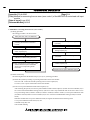
TECHNICAL BULLETIN
[Issue No.] FA-A-0085
[Page] 1/4
[Title] Method for recovering from an error (error code 1) of the MELSEC-Q series load cell input
module
[Date of Issue] June 2010
[Relevant Models] Q61LD
Thank you for your continued support of Mitsubishi programmable controllers, MELSEC-Q series.
This bulletin describes the method for recovering from an error (error code 1) of the Q61LD*1.
*1: The following shows the relevant Q61LD models.
y Production information: The first 5 digits is 12031 or earlier. (The first 5 digits is 12032 or later is inapplicable.)
y Product information: The first 5 digits is 11031. (The first 5 digits is 12011 or later is inapplicable.)
The production information can be checked on the rating plate on the module side.
The product information can be checked in the System Monitor screen of a programming tool.
For details on the check methods, refer to the Q61LD Load Cell Input Module User's Manual (SH(NA)-080821ENG).
Contents
1. Causes of the error code 1 ................................................................................................................................................... 1
2. Method for recovering from an error (error code 1) ........................................................................................................... 2
1. Causes of the error code 1
The error code 1, hardware error in the module, is detected when an analog input (load cell output) exceeds the conversion
range or when hardware fails due to incorrect setting or incorrect wiring.
No.
Cause
1
Excessive analog input (load cell output) is being applied to the module.
2
The gain value set inside the module is too great.
3
Input (between SIG + and SIG - terminals) is open.
4
The hardware fails.
Example
The selected load cell input module model is
not appropriate.
Automatic calibration was performed with
incorrect two-point setting value.
The cable is disconnected.
-
Errors occurred by the No.1 or No.2 cause in the above table can be recovered by defaulting Two-point setting value (Un\G50
to Un\G54, Un\G56 to Un\G60, Un\G62 to Un\G71) and Two-point calibration value (Un\G80 to Un\G87).
After defaulting the values, check the specifications, usage, wiring, and setting values of the load cell and perform two-point
setting and two-point calibration again.
HEAD OFFICE : TOKYO BUILDING, 2-7-3 MARUNOUCHI, CHIYODA-KU, TOKYO 100-8310, JAPAN
NAGOYA WORKS : 1-14, YADA-MINAMI 5-CHOME, HIGASHI-KU, NAGOYA, JAPAN
TECHNICAL BULLETIN
[Issue No.] FA-A-0085
[Page] 2/4
[Title] Method for recovering from an error (error code 1) of the MELSEC-Q series load cell input
module
[Date of Issue] June 2010
[Relevant Models] Q61LD
2. Method for recovering from an error (error code 1)
(1) Setting procedure
The setting procedure is as shown below.
Start (The error code 1 is detected.)
(a) Restart the system by resetting or
powering off and then on the CPU
module.
(b) Turn on Two-point calibration mode
switch request (YA).
(c) Set User setting (1H) to Two-point
calibration method setting (Un\G41).
(d) Write the default two-point setting value
and the default two-point calibration
value to the corresponding buffer
memories.
(e) Set Write (1H) to Two-point setting
(Un\G40).
(f) Turn off, on, and then off Two-point
setting request (Y7).
(g) Check that the conversion range is not
exceeded.
(h) Turn off Two-point calibration mode
switch request (YA).
End (Perform two-point calibration again.)
(2) Details of each step
The following describes the details of steps (a) to (h) in (1) Setting procedure.
(a) Restart the system by resetting or powering off and then on the CPU module.
The error code 1 cannot be cleared by turning on Error clear request (YF).
To clear it, reset or power off and then on the CPU module.
(b) Turn on Two-point calibration mode switch request (YA).
After restarting the system, turn on Two-point calibration mode switch request (YA) while Conversion disable (1H) is
set to Conversion enable/disable setting (Un\G0). (The error code 1 may be detected when an incorrect value is set to
Two-point setting value (Un\G50 to Un\G54, Un\G56 to Un\G60, Un\G62 to Un\G71) or Two-point calibration value
(Un\G80 to Un\G87) while Conversion enable (0H) is set to Conversion enable/disable setting (Un\G0) in normal
mode.)
When the module enters two-point calibration mode, the signals and LED enter the following status.
y Two-point calibration mode status (XA): On
y Module ready (X0): Off
y RUN LED: Flashing
HEAD OFFICE : TOKYO BUILDING, 2-7-3 MARUNOUCHI, CHIYODA-KU, TOKYO 100-8310, JAPAN
NAGOYA WORKS : 1-14, YADA-MINAMI 5-CHOME, HIGASHI-KU, NAGOYA, JAPAN
TECHNICAL BULLETIN
[Issue No.] FA-A-0085
[Page] 3/4
[Title] Method for recovering from an error (error code 1) of the MELSEC-Q series load cell input
module
[Date of Issue] June 2010
[Relevant Models] Q61LD
(c) Set User setting (1H) to Two-point calibration method setting (Un\G41).
Two-point calibration value (Un\G80 to Un\G87) can be directly changed by storing User setting (1H) to Two-point
calibration method setting (Un\G41).
Two-point calibration value (Un\G80 to Un\G87) cannot be directly changed when Automatic setting (0H) has been set
to Two-point calibration method setting (Un\G41).
(d) Write the default two-point setting value and the default two-point calibration value to the corresponding buffer
memories.
Write the default values to Two-point setting value (Un\G50 to Un\G54, Un\G56 to Un\G60, Un\G62 to
Un\G71) and Two-point calibration value (Un\G80 to Un\G87).
Note the following.
y Write the value stored in 3.0mV/V zero calibration value (Un\G1622, Un\G1623) to Two-point zero calibration value
(Un\G84, Un\G85).
y Write the value stored in 3.0mV/V span calibration value (Un\G1624, Un\G1625) to Two-point span calibration
value (Un\G86, Un\G87).
(e) Set Write (1H) to Two-point setting (Un\G40).
Set Write (1H) to Two-point setting (Un\G40).
(f) Turn off, on, and then off Two-point setting request (Y7).
Turn off, on, and then off Two-point setting request (Y7).
Changes made to Two-point setting value (Un\G50 to Un\G54, Un\G56 to Un\G60, Un\G62 to Un\G71) and
Two-point calibration value (Un\G80 to Un\G87) become valid.
(g) Check that the conversion range is not exceeded.
To check that the newly set value does not exceed the conversion range of the analog input (load cell output), set
Conversion enable (0H) to Conversion enable/disable setting (Un\G0) and turn off, on, and then off Operating
condition setting request (Y9) (Conversion processing will start).
Turn on Error clear request (YF) and check that Excess of conversion (1) is not stored in the bit 3 of Input signal error
detection flag (Un\G114).
If Excess of conversion (1) is stored, the error may not be due to incorrect setting.
Check that the cables are not disconnected and correctly wired, and a voltage across the input terminals (between SIG+
and SIG- terminals) does not significantly exceed 15mV.
(h) Turn off Two-point calibration mode switch request (YA).
Turn off Two-point calibration mode switch request (YA) to return the two-point calibration mode to normal mode.
When the module enters normal mode, the signals and LED change to the following status.
y Two-point calibration mode status (XA): Off
y Module ready (X0): On
y RUN LED: On
HEAD OFFICE : TOKYO BUILDING, 2-7-3 MARUNOUCHI, CHIYODA-KU, TOKYO 100-8310, JAPAN
NAGOYA WORKS : 1-14, YADA-MINAMI 5-CHOME, HIGASHI-KU, NAGOYA, JAPAN
TECHNICAL BULLETIN
[Issue No.] FA-A-0085
[Page] 4/4
[Title] Method for recovering from an error (error code 1) of the MELSEC-Q series load cell input
module
[Date of Issue] June 2010
[Relevant Models] Q61LD
(3) Precautions
If the usage or set value of the load cell is incorrect, an error may occur again after the set value is changed or two-point
calibration is performed even if the system is recovered from an error (error code 1) by the procedure shown in this chapter.
If the error code l is detected again, check the following.
y Specifications of the connected load cell
y Two-point setting value (Un\G50 to Un\G54, Un\G56 to Un\G60, Un\G62 to Un\G71)
y Two-point calibration value (Un\G80 to Un\G87)
y Procedure for two-point calibration
HEAD OFFICE : TOKYO BUILDING, 2-7-3 MARUNOUCHI, CHIYODA-KU, TOKYO 100-8310, JAPAN
NAGOYA WORKS : 1-14, YADA-MINAMI 5-CHOME, HIGASHI-KU, NAGOYA, JAPAN