1
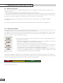
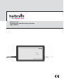
Haibrain X-10
Programming and Measuring Interface
Type PMIX35
Introduction
The Programming and Measuring Interface (PMIX35) is a power line communication interface suitable for Haibrain X-10 and
other compatible systems (such as X-10). In addition to supporting the standard and extended protocols of Haibrain X-10, this
interface also measures the quality of various signals. With the supplied PMIX35 software, technical problems in installations
can be quickly localised and resolved, a new installation can be tested for reliability and modules can be quickly and easily
programmed.
Functions
Contents
• Sending and receiving commands.
• Measuring the signal level and noise level of incoming
messages.
• Measuring network impedance.
• Sending messages with quick-selection buttons.
• Sending messages with two preset macros.
• Running macros automatically.
• Sending messages with adjustable transmission levels.
• Logging of received and sent messages with error
analysis.
• Easily accessible network diagnostic information.
• Automatic programming of modules at the touch of a
button.
• Network validation measuring method with reporting for
the reliable delivery of new installations (available
starting from software version 1.1).
• Support for the PMIX35 ASCII protocol similar to the
CTX15/35 protocol.
• Support for the CTX15/35 protocol.
In
•
•
•
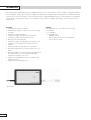
Figure 1: PMIX35
2
the PMIX35 box, you should find the following:
1x PMIX35
1x USB cable
1x CD-ROM with:
- PMIX35 software
- PDF operating instructions for the PMIX35
- Quick reference guide
Software installation
Follow the steps below to install the PMIX35 software.
! Please note:
Follow the installation procedure below before connecting the PMIX35 to the PC!
1. Place the PMIX35 CD in the CD-ROM drive of the PC.
If the installation does not start automatically, then follow the steps below:
a. Open Windows Explorer and go to the CD-ROM drive in which the PMIX35 CD is located.
b. Click the SETUP.EXE file to start it.
c. Click Run to start the installation.
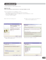
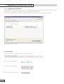
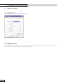
2. Click "Next" in the following screen:
3. Read the terms and conditions and accept them to
continue with the installation process.
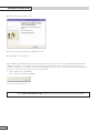
4. Chose a different folder or location, if desired, and click
5. Wait until the installation is complete.
"Install" in the following screen:
3
Software installation
6. Click "Finish" in the following screen:
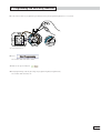
7. Now connect the USB cable of the PMIX35 to the PC.
8. The PMIX35 is now ready for use.
After starting up, the PMIX35 software will automatically search for the presence of a connected PMIX35 and attempt to
establish a connection. The software verifies whether the correct firmware version is in use. If this is not the case, the
software will load the correct firmware version into the PMIX35. The status of the connection is indicated in the lower right
part of the screen by the following two indicators (see figure 2):
• Yellow: Signals sent to the PMIX35.
• Green: Signals received by the PMIX35.
Figure 2: Connection with PMIX35 indicator
Check http://www.haibrain.com. regularly for new software versions for the PMIX35
4
1 Programming and measuring functions
The PMIX35 software can be used for:
• Programming Haibrain X-10 modules.
• Measuring and testing an installation.
For this purpose the PMIX35 software is divided into three tab pages, namely:
1. Programmer
2. Analyzer
3. Network Validation (available via a software update from mid-2008)
The table below gives an overview of these functions and their applications:
Tab page name
Purpose
Programmer
Programming modules
Analyzer
Problem analysis
Application
All Haibrain X-10 modules can be easily programmed using this function.
Highly specific measurements for analysis can be carried out in a Haibrain X-10
installation using this function.
Network Validation
Validation of an installation
This function validates the reliability of a new, yet to be delivered Haibrain X-10
installation with a validation report and a final assessment.
Table 1 1: Overview of software functions.
In the following chapters each individual tab page with its specific functions will discussed in detail.
1.1
Programmer
The purpose of the Programmer tab page is to allow the simple programming of Haibrain X-10 modules.
The required settings are preset and programmed in the module at the touch of a button.
The latest Haibrain X-10 modules can be automatically placed in program mode (PRG function) without having to remove the
module to press the program button. The module types that support this PRG function can be found in the table below:
Type
Description
PRG function
IMX10 / TWM4
Programmable interface potential-free inputs
Yes
SAIX12 / AWM2P
Switch actuator/switch interface 230 V AC inputs
Yes
DAIX12 / LWM1P
Dimming actuator/dimmer interface 230 V AC inputs
Yes
PIOX15 v2
Potential-free input/output interface
Yes
SAX15 v2
Switch actuator/switch interface potential-free
Yes
SVX10 v2
Signal amplifier
Yes
SAIX / AWM2
Switch actuator/witch interface potential-free inputs
No
SAX1
Switch actuator
No
DAIX10 / LWM1
Dimming actuator/dimmer interface potential-free inputs
No
DAX10
Dimming actuator
No
AIX / TMA4
Switch interface potential-free inputs
No
AIX12
Switch interface 230 V AC inputs
No
DIX1
Dimmer interface single-face potential-free inputs
No
DIX2
Dimmer interface two-face potential-free inputs
No
GIX
Group interface potential-free inputs
No
SVX10 v1
Signal amplifier
No
PIOX15 v1
Potential-free input/output interface
No
SAX15 v1
Switch actuator/switch interface potential-free
No
SAX35
witch actuator/switch interface potential-free
No
VIX10
Fan interface
No
ZAX12 / SWM1P
Sunscreen interface potential-free
No
Table 1 2: Module types.
The following paragraphs describe the programming method for both types of modules.
5
1 Programming and measuring functions
1.1.1
Programming standard modules
Standard modules (without PRG function, see table 1-2) can be easily programmed by selecting the required module settings.
After that, these settings can be programmed in the module at the touch of a button.
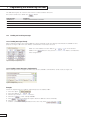
In order to program a module, a number of steps must be followed. These steps are described on the next page.
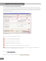
Figure 3: Example of programming an SAIX.
Programming steps:
1. Select the module to be programmed at the top of the tab page:
2. Select the required address:
3. Select the required options:
4. Select any extra options using:
6
1 Programming and measuring functions
5. Switch the module to programming mode by pressing the programming button for 3 seconds.
P
PROG.
SAIX
12
N
L
PROG.
The module LED switches on.
6. Click:
The module LED will start to flash.
7. Wait for the green indicator:
8. Exit programming mode by pressing the programming button again briefly.
The module LED switches off.
7
1 Programming and measuring functions
1.1.2
Programming using automatic programming mode
The latest generation of Haibrain X-10 modules can be (re)programmed by means of a special procedure without having to
remove the module. This procedure, which must be followed precisely, is based on interaction between the PMIX35 and the
module. The module can be programmed by operating a switch or pushbutton, or by switching the connected load on and off
(in electrical wall sockets), in combination with the software. The module will not enter the programming mode if any of the
conditions have not been met.
Read through the instructions below carefully and follow them precisely.
Figure 4: Programming steps
The steps for automatic programming mode are as follows:
1
Select the module type by pressing the tab page.
2
Select the function required for the first input wire.
3
Select the address required for the first input wire.
4
If necessary, select the options for the first input wire.
5
If necessary, select the function, the address and options for the other input wires.
6
Verify whether the current address of the module is selected here. All new modules have the default address A01.
This is necessary to activate the PRG function in this module.
1. Click:
2. Wait until the green indicator light is illuminated:
8
1 Programming and measuring functions
3. Within 5 seconds, activate the programming mode of the module according to the table below:
Type
Activation of programming mode
IMX10
Switch one of the inputs 4 times within 5 seconds using the switch or pushbutton.
SAIX12
Switch one of the inputs 4 times within 5 seconds using a switch or pushbutton or switch the connected load
DAIX12
(wall socket) on and off 4 times within 5 seconds.
The programming starts:
4. Wait for the indicator:
If programming does not start automatically:
• Press:
and repeat the instructions above or
• Press the programming button of the module within the time indicated by:
The PMIX35 makes three attempts
1.2
, before stopping the procedure.
Analyzer
The purpose of the Analyzer tab page is to measure and analyse the quality of the data transfer over the power line. For a
good analysis, various settings can be made, in many cases requiring specific knowledge. Where in the installation the
measurement is carried out is also important.
All measurements take place via the power cord of the PMIX35.
The explanation of the application of the Analyzer function is divided into a number of practical components. The table below
gives an overview of these components and their possibilities:
Component
Measuring signal levels
Possibilities
The signal levels of all messages transmitted and received are displayed in the log screen. In this way, unreliable
signal levels are immediately noticeable. By varying the transmission level of the transmitted messages, the
sensitivity of the receiving side of a module can be measured.
Network diagnostics
The network diagnostic indicators offer direct insight into possible areas of interest.
Sending and receiving
Messages can be sent directly or be placed in a macro before they are sent. The macros can be sent
messages
automatically at certain intervals. Messages that are transmitted and received can be found in the log screen.
Logging and viewing
The status of the received messages is indicated in the log screen by means of colour shading.
message communication
In this way, communication faults are immediately noticeable. The saved log file can be imported into Excel,
for example, for further analysis.
Table 1 3: Analyzer components.
9
1 Programming and measuring functions
1.2.1
Measuring signal levels
The measuring of signal levels in Haibrain X-10 installations allows the rapid detection and resolution of problems. A few
examples of this are:
• One or more modules appear to be inaccessible after switching on one module.
• Switching this module On has an affect on various signal levels. The load connected to this module is causing the problem.
• Some of the modules do not work at certain times. The signal levels of some of the modules lie below the required level.
At the times when these modules do not respond, the noise level is shown to be much higher.
The automatic measuring of the signal quality can be performed most simply via the network validation tab page.
See chapter 1.3.
The measuring of signal levels can also be performed for individual modules. This procedure is described below.
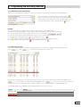
1.2.1.1 Signal levels of modules
The signal level and noise level of each message received is measured. These values can be found in the log screen as well
as in the log file next to the received message. These values are reported in mV.
The readings from the two most recently received messages can also be found on the large display fields in order to quickly
gain insight into current events. An important factor in power line communication is network impedance. The value of the
power line impedance is reported in Ohm (see figure 5).
Figure 5:
Display of latest readings.
During measuring, always take the following points into account to be able to properly assess
the signal level of a module:
• Before the measuring starts, switch all appliances in the home on. By doing so, the effect of
the switched on appliances is included in the measurement.
• Perform the same measurement at more than one socket in the home.
• Always look at the noise level. The higher the noise level, the more signal is necessary to be
able to function properly. It can happen that an appliance has a negative effect on the noise
level and, therefore, communication. Provide this appliance with a filter.
• Always look at the network impedance. It can happen that an appliance has a negative effect
on the network impedance and, therefore, communication. Provide this appliance with a filter.
• The network impedance should not be lower than 2 Ω.
For maximum reliability, the signal levels must comply with the threshold values as indicated in figure 6. If the signal level
falls into the yellow area, it is important to check whether the module continues to function properly in all cases. If the signal
level falls in the red area, action must always be taken to improve the signal quality.
Fault
0
Check
100 mV
Figure 6: Signal level thresholds for modules.
10
Good
200 mV
Max
1 Programming and measuring functions
1.2.1.2 Sensitivity of modules
The sensitivity of modules can be measured by varying the transmission level of the messages. By doing so, it is possible to
determine at which level the module no longer reacts. To do this, slide the selector from left to right (see figure 7).
Follow the steps below to measure the sensitivity of a module starting from the measurement
site:
1. Enter ON/OFF or Status Request commands in the command lines for controlling the relevant
module (see paragraph 1.2.3.2 Sending several messages simultaneously). For interface
modules, make use of following the status.
Figure 7:
2. Slide the "Transmit Voltage" selector all the way to the right (maximum) and send several
Setting the transmission level.
ON/OFF commands to check the operation of the module. The signal level sent is then
displayed in the large display field underneath.
3. With the selector, find the lowest point at which the module still responds properly. Take the value of the transmission
signal from the display field below.
4. Check where this value falls within the thresholds depicted in the figure below:
Good
Check
0
2V
Fault
4V
Max
Figure 8: Sensitivity thresholds of modules.
5. If the signal level falls into the yellow area, it is important to check whether the module continues to function properly in
all cases.
1.2.2
Network diagnostics
The Network Diagnostics indicators and the Counters (see figure 9) offer quick insight into specific events.
Figure 9: Network diagnostics data.
The table on the below gives an overview of the diagnostic indicators and their functions. The indicators are displayed until all
indicators are reset with the
button.
Indicator name
Diagnostics
Repeater detected
Indication that the signal level measured from the 2nd address/command received is higher than the 1st over the
course of several measurements.
Module noise detected
Indication that the PMIX35 detects signal interference that disrupts communication.
Lost command detected
Indication that a suspect message has been detected in the log screen, indicated by red shading.
<200 mV detected
Indication that a signal lower than 200 mV has been measured.
<100 mV detected
Indication that a signal lower than 100 mV has been measured.
Impedance drop detected
Indication that the impedance measured changes a specified delta X.
Lines shown in this colour require extra attention.
Table 1 4: Network diagnostics indicators.
11
1 Programming and measuring functions
The table below gives an overview of the various counters and their functions.
All counters can be set to 0 with the
button.
Indicator name
Diagnostics
All Addresses
Counter value of all addresses received.
All Commands
Counter value of all commands received.
DIM/BGT Commands
Counter value of all DIM and BRIGHT commands received.
Extended commands
Counter value of all extended data received.
Table 1 5: Counters.
1.2.3
Sending and receiving messages
1.2.3.1 Sending messages directly
When sending messages, the required addresses and commands can be sent directly with the buttons available for this
purpose (see figure 10). In this case "Add to command line" must not be selected.
Make use of the address selection buttons
to choose another
address. The
button is only used for the selection of "Add to command line"
when using macros.
Figure 10: Sending messages directly.
1.2.3.2 Sending several messages simultaneously
When sending several messages simultaneously, the two available command lines can be used (see figure 11).
Figure 11: Sending messages indirectly.
Example:
Follow the steps below for sending a Status Request to the address "A01".
1. Select the option:
2. Select the address:
3. Click the top command line with the mouse.
4. Click twice on
, in this example A01A01.
5. Click
(there must always be a space between addresses and commands).
6. Click twice on
7. Send the command line using the button next to the entry field.
12
1 Programming and measuring functions
1.2.3.3 Sending messages automatically
With the two command lines available, two series of messages can be sent automatically in a specified pattern.
The command lines can be saved in a macro file with the
button. To do this, choose the file name required and save. All
command lines entered and sent can be selected with the arrow
keys. An existing macro can be opened with the
button.
Figure 12: Sending messages automatically.
Example:
Follow the steps below to automatically send two command lines to the address "A01".
1. Follow the steps in paragraph 1.2.3.12 to provide both command lines with the required messages.
2. Select the option and the required delay time for the first command line:
3. Select the option and the required delay time for the second command line.
4. Start automatic sending by clicking:
(this symbol then becomes:
).
5. The
indicator for the command lines indicates in yellow which line is waiting to be sent.
6. Sending can be cancelled by clicking:
(this symbol then becomes:
).
1.2.3.4 Receiving messages
As well as messages that are transmitted, messages that are received are also displayed, with their arrival times,
in the
and
columns in the log window (see figure 13).
Figure 13: Received messages log screen.
According to the X-10 protocol, messages are always sent twice consecutively. The first message always appears in the
column and the second message always appears in the
column. If the second message is not
received, the second column will be empty. Single messages occur normally with Phase Couplers and Repeaters.
See the table below for an explanation of the different data colours in the log screen.
Log line
Meaning
Received message.
Transmitted message.
Suspect message. Lines shown in this colour require extra attention.
Table 1 6: Log line colour meanings.
13
1 Programming and measuring functions
Errors in the log screen are indicated with red shading.
The table below gives several examples of suspect messages:
Suspect messages
Description
" "A01" "AONAON
If one of the double addresses or commands is missing. This does not apply to repeated messages for which the
" "A01A01" "AON
address and the command consist of only one message.
If there is no space between two different messages.
A01AON
A01BDIM
A01B03
AONAOFF
AONBON
A01A[1]031531
AONA[1]031531
A01" "BON
If an address is followed by a command with a different letter code.
A01" "B02
If an address is followed by an address with a different letter code.
Table 1 7: Examples of faulty message patterns.
The example of sending a Status Request to the address "A01" from chapter 1.2.3.2 Sending several messages
simultaneously can be found in the log screen as shown below:
Go to the next chapter for more information about the interpretation of log information.
1.2.4 Logging and reading data communication
Information if the log screen can be saved in a log file with the
save. The log screen can be cleared with the
button.
A log file looks like this:
button. To do this, choose the file name required and
Sample log file: pmix35.log
Date / Time
11/30/2007 12:10:43
11/30/2007 12:10:43
11/30/2007 12:10:46
11/30/2007 12:10:46
11/30/2007 12:10:50
11/30/2007 12:10:51
11/30/2007 12:11:01
11/30/2007 12:11:01
11/30/2007 12:11:08
11/30/2007 12:11:08
11/30/2007 12:11:09
11/30/2007 12:11:09
11/30/2007 12:11:13
11/30/2007 12:11:13
11/30/2007 12:11:16
11/30/2007 12:11:16
11/30/2007 12:11:17
11/30/2007 12:11:17
11/30/2007 12:11:31
11/30/2007 12:11:48
11/30/2007 12:11:48
11/30/2007 12:11:48
11/30/2007 12:11:50
11/30/2007 12:11:50
PM
PM
PM
PM
PM
PM
PM
PM
PM
PM
PM
PM
PM
PM
PM
PM
PM
PM
PM
PM
PM
PM
PM
PM
Space
S
S
S
S
S
S
S
S
S
S
S
S
S
S
S
S
S
S
S
S
S
S
S
S
Data1
A01
AOFF
A01
AON
A02
AOFF
A01
AOFF
A01
ASRQ
A01
ASOF
A01
AON
A01
ASRQ
A01
ASON
A01
A01
A01
ASRQ
A01
ASOF
Level1
555
554
555
554
563
566
566
544
2933
2929
558
559
3903
3899
3893
3886
564
564
550
880
880
879
561
553
Noise1
85
89
85
89
89
98
90
84
90
100
83
84
90
90
86
93
84
86
90
87
87
100
88
84
Data2
A01
AOFF
A01
AON
A02
AOFF
A01
AOFF
A01
ASRQ
A01
ASOF
A01
AON
A01
ASRQ
A01
ASON
A01
Level2
556
556
556
557
559
563
564
555
2931
2926
557
568
3898
3892
3890
3887
559
561
558
Noise2
83
86
87
82
93
89
89
87
95
92
89
84
91
90
88
95
83
78
83
880
876
568
560
89
96
84
80
Status
Suspicious
A01
ASRQ
A01
ASOF
Echo
No Echo
No Echo
No Echo
No Echo
No Echo
No Echo
No Echo
No Echo
Echo
Echo
No Echo
No Echo
Echo
Echo
Echo
Echo
No Echo
No Echo
No Echo
Echo
Echo
Echo
No Echo
No Echo
Table 1 8: Log file.
Errors that appear in the log screen with red shading (see table 1-6) are indicated in the log file with the message "Suspicious".
14
1 Programming and measuring functions
1.3
Network validation
In this tab page, a quick and simple network analysis can be performed before the delivery of a Haibrain X-10 installation.
By making a selection of the addresses used, the PMIX35 will perform a number of measurements and present a report
which includes the areas of interest of the Haibrain X-10 installation.
1.3.1
Performing network validation
When performing network validation, the tab page "Network validation" must first be selected. Select the letter codes used in
the Haibrain X-10 installation by clicking the relevant boxes, thereby selecting the letter code(s).
In the fields on the top right corner, the name and address details of the customer where the measurement is taking place
can be entered. Any comments can be entered in the remarks field. Once the measurement is complete, this data can be
saved and compared with the data from any subsequent measurements.
! Please note:
Before validation can be started, it is important to switch on all of the appliances in the home that are connected to the
power line. Switching on means bringing the appliance to working voltage, as opposed to leaving them in stand-by mode.
Appliances such as dishwashers, washing machines, dryers, computer monitors, TVs etc. must be switched on. In this way,
the measurement will be made under the most adverse conditions, so the result gives a good picture of the points that
require attention to guarantee reliable data transfer.
Figure 14: Network validation tab page.
Press "Start Validation" as soon as all appliances in the home have been switched on. The PMIX35 will now begin
transmitting data to and receiving data from the modules that are present in an installation. This process can take up to
10 minutes or so depending on the number of letter codes.
! Please note: Make sure that no switches are operated during this process and that any motion detectors are not
activated while the measurement is being made. Do not interrupt the test; allow the PMIX35 to run through the entire process.
15
1 Programming and measuring functions
1.3.2 Interpreting the network validation data
The PMIX35 software will display the transmission, reception, noise and impedance levels per address.
In the "Result" column, the software displays the result of the measuring process for the relevant address.
There are four possible results, namely:
• Not Found: the address was not found in the installation. The line is coloured white.
• Passed: the results are good. No further action is necessary. The line is coloured green.
• Check: the results give cause to re-examine the situation around the module at this address. The line is coloured orange.
• Failed: the results indicate that under the current circumstances no reliable communication is possible to and/or from this
module. The line is coloured red.
The result is established by an analysis of the software on the basis of the signal level and noise level. As soon as there are
low signal levels, the result is clear. However, it can also occur that the signal levels are good (above the minimal values) but
that there is a very large difference between the signal levels of an ON and an OFF command in a module. The PMIX35
software will also indicate this address as "check".
It is advisable to repeat the validation test for the modules that receive a "check" or a "fail" result. Before repeating the test,
switch off one or more appliances in the vicinity of the module you wish to check. If the repeat validation gives a better
result, this means that the appliances in question have a damping effect on the signal quality. Isolate the appliances with one
or more filters. If the signal levels do not change after switching off the appliances, this can mean that there are other factors
causing the signal strengths to be inadequate. In this situation, a signal amplifier (SVX10) can offer a solution to improve the
signal levels.
The measurement data can be saved by clicking the button. Another possibility is to select the data and copy and paste it into
a spreadsheet program.
16
2 The PMIX35 as data interface
The PMIX35 supports the CTX15/35 protocol as standards and, in addition, has a number of extra functions. This means that
the PMIX35 can directly replace the CTX15/35 without having to adapt the software.
2.1
PMIX35 communication driver
The PMIX35 is equipped with a USB connection based on a CP210x virtual COM port. The installation software automatically
installs the CP210x USB to UART Bridge Virtual COM Port (VCP) drivers, so that the PMIX35 can communicate via the USB
port of a PC.
The drivers are available for the following operating systems:
• Windows 2000/XP/Server 2003/Vista
• Macintosh
• Linux
During the installation, the software also checks whether the firmware version which belongs with the installed software is
loaded in the PMIX35. If this is not the case, the software will load the correct firmware version.
2.1.1
Example using Windows 2000/XP driver
After the installation of the USB drivers on the Windows XP operating system, the name of this COM port can be found
under "Device Manager" in the hardware overview in the configuration screen in XP (see figure 15).
Figure 15: Windows XP Device Manager USB Driver.
The COM port number assigned to the PMIX35, COM5 in this case, follows the driver name "CP2101 USB to UART Bridge
Controller". Now, communication with the PMIX35 can occur via this COM port.
17
2 The PMIX35 as data interface
2.2
Protocol description
2.2.1
COM port settings
See the figure below for the required COM port settings:
Figure 16: Port settings.
2.2.2 COM port detection
The COM port to which the PMIX35 is connected can be detected by sending the "PX" command. As the PMIX35 will answer
this command, the correct COM port can be automatically selected.
18
2 The PMIX35 as data interface
2.2.3
Communication format
All communication is ASCII format. The messages between the PC application and the PMIX35 are equipped with headers.
The PC application always takes the initiative and the PMIX35 answers it. See the table below for the format.
$>9000{message}cs#
Communication direction: PC -> PMIX35
$
Start character.
>
Communication direction from PC to PMIX35.
9000
PMIX35 address.
{message}
Message for PMIX35.
cs
Checksum: sum of all characters except the end character.
#
End character.
$<9000{bericht}cs#
Communication direction: PMIX35 -> PC
$
Start character.
<
Communication direction from PMIX35 to PC.
9000
PMIX35 address.
{message}
Message for PC.
cs
Checksum: sum of all characters except the end character.
#
End character.
Table 2 1: Format headers.
There are various types of messages, including messages which contain X-10 traffic. These messages contain not only the X10 format but also the accompanying signal levels. The table below shows the X-10 format:
<L><AA>
Address
L
16 letter codes, A to P.
AA
16 addresses, 01 to 16.
<L><CC[C]>
Command
L
16 letter codes, A to P.
CC[C]
commands: ON, OFF, DIM, BGT, AUF, ALN, ALF, HRQ, HAK, PRG, SON, SOF, SRQ.
<L>[1]<AA><EEEE>
Extended
L
16 letter codes, A to P.
AA
16 addresses, 01 to 16.
EEEE
Extended code hexadecimal.
" "
Space
" "
The space character. This corresponds to a specific time between the different messages.
Messages which are different from each other are always separated by a space.
Table 2 2: Format X-10.
19
2 The PMIX35 as data interface
2.2.4
Types of messages
The tables below describe the different types of messages. See the next section for an example of a checksum "cs" calculation.
Transmitter
Format
Description
PC
PX
PMIX35: "Are you PMIX35" message to ask COM ports whether a PMIX35 is connected to the COM port.
The PMIX35 reacts to this message within 1000 ms with VP.
PMIX35
VP{MMmm}
Version PMIX35: This message is sent to the PC application as a response to PX. This also contains the
version number of the PMIX35.
Parameters:
MM
-
Major Version Number in two-byte decimal ASCII notation.
mm
-
Minor Number in two-byte decimal ASCII notation.
Example: $<9000VP0131cs#
Corresponds to version 1.31.
Table 2 3: Message: PX (Are you PMIX35).
Transmitter
Format
Description
PC
TV{VVVV}
Transmit Voltage: The transmit voltage of the PMIX35 is set with this message.
Parameters:
VVVV
-
Voltage in two-byte decimal ASCII notation; valid range between 0-5000 mV.
Example: $>9000TV2500cs#
Corresponds to a transmit voltage of 2500 mV.
PMIX35
{s}
This message gives an ACK or NACK indicator for the received message.
Parameters:
s
-
"!" ACK.
"?" NACK transmit again (maximum three times).
Example: $<9000!cs#
Message has been received.
Table 2 4: Message: TV (Transmit Voltage).
Transmitter
Format
Description
PC
SP{D}
Send Position: The position of the transmitted data on the mains voltage with respect to the zero crossing
is set with this message.
Parameter:
D
-
"1" Transmit at: 0 degrees.
"2" Transmit at 30 degrees.
"3" Transmit at 0 and 30 degrees.
"4" Transmit at 60 degrees.
"5" Transmit at 0 and 30 degrees.
"6" Transmit at 0 and 60 degrees.
"7" Transmit at 0, 30 and 60 degrees.
Example: $>9000SP1cs#
Transmit data at 0 degrees.
PMIX35
{s}
This message gives an ACK or NACK indicator for the received message.
Parameters:
s
-
"!" ACK.
"?" NACK transmit again (maximum three times).
Example: $<9000!cs#
Message has been received.
Table 2 5: Message: SP (Send Position).
20
2 The PMIX35 as data interface
Transmitter
PC
Format
RQ
PMIX35
ND{SS}
PMIX35
NI{OOOO}
PMIX35
LR{VVVV}{NNNN}{LL…L}
LE{VVVV}{NNNN}{LL…L}
PMIX35
{s}
PC
?
Description
Data Request: After the connection has been established, a Data Request is made to the PMIX35
with a period of 500 ms. The PMIX35 can answer with the following message types:
ND
- Noise detected.
NI
- Network Impedance.
LR/LE - Line Read/Line Echo.
? - Message not properly received.
These messages can appear in the answer together or separately.
Example: $>9000RQcs#
Module Noise Detected: When changing state, this message is sent along with the other messages.
Parameters:
SS
- State in one-byte decimal ASCII notation; 00 = No Noise Detected,
01 = Noise Detected.
Example: $<9000ND01cs#
Corresponds to: There is Module Noise Detected.
Network Impedance: Every 5 seconds, this message is sent along with the other messages.
Parameters:
OOOO - Impedance in two-byte decimal ASCII Notation;
valid range between 0-9999 10th of an Ohm.
Example: $<9000NI0047cs#
Corresponds to a Network Impedance of 4.7 Ohm.
LR/LE - Line Read/Line Echo: Data packet read by the PMIX35 on the circuit, transferred
transparently to the PC application. The voltage and noise that the message was received with
are also provided. The "LE" indicates that the data packet received had been sent by the
PMIX35 itself.
Parameters:
VVVV - Voltage in two-byte decimal ASCII notation; valid range between 0-6000 mV.
NNNN - Noise Level in two-byte decimal ASCII notation; valid range between 0-6000 mV.
LL..L - Line in variable length ASCII notation.
Description:
Example 1: $<9000LR35000300A01cs#
Received: A01 with 3500 mV and 300 mV noise.
Example 2: $<9000LE35000300AOFFcs#
Received echo: AOFF with 3500 mV and 300 mV noise.
Example 3: $<9000LR35000300 A01cs#
Received: A01 preceded by a space with 3500 mV and 300 mV noise.
This message gives a NACK indicator for the received message.
Parameters:
s
- "?" NACK transmit again (maximum three times).
Example: $<9000?cs#
Message not properly received.
Nack: After the connection has been established, a Data Request is made to the PMIX35 with a
period of 500 ms. The PMIX35 can answer with the following message types:
ND
- Noise detected.
NI
- Network Impedance.
LR/LE - Line Read/Line Echo.
These messages can appear in the answer together or separately.
Example: $>9000?cs#
Examples of combined messages. Only one of each type can appear in these messages.
The LR/LE messages are always at the end of the line.
$<9000NI0047LR35000300A01cs#
$<9000ND01NI0047LE35000300 AOFFcs#
$<9000ND01LR35000300 A01cs#
Table 2 6: Message: RQ (Data Request).
21
2 The PMIX35 as data interface
Transmitter
Format
Description
PC
LW{LLL..L}
Line Write: With this message, the PC application commands the PMIX35 to transfer data transparently
on the circuit.
Parameters:
-
LL..L
Line in variable length ASCII notation. Corresponds to the data entered in the
"Macro entry fields". See item 4 Fout! Verwijzingsbron niet gevonden.
Example: $>9000LW A01A01 AONAONcs#
Corresponds to switching on everything on A01.
PMIX35
{s}
This message gives an ACK or NACK indicator for the received message.
Parameters:
s
-
"!" ACK.
"?" NACK transmit again (maximum three times).
Example: $<9000!cs#
Message has been received.
Table 2 7: Message: LW (Line Write).
22
2 The PMIX35 as data interface
2.2.4.1
Sample checksum calculation
To receive data from the PMIX35, a request must be sent to the PMIX35.
This request is described in Table 2 6: Message: RQ (Data Request) and looks like this:
$>9000RQcs#
To calculate the checksum "cs", the hexadecimal values of all of the previous characters must be added together
hexadecimally. These values can be found in the ASCII table below:
Hex
Code
Hex
Code
Hex
Code
Hex
Code
Hex
Code
Hex
Code
20
(Space)
30
0
40
@
50
P
60
`
70
p
21
!
31
1
41
A
51
Q
61
a
71
q
22
"
32
2
42
B
52
R
62
b
72
r
23
#
33
3
43
C
53
S
63
c
73
s
24
$
34
4
44
D
54
T
64
d
74
t
25
%
35
5
45
E
55
U
65
e
75
u
26
&
36
6
46
F
56
V
66
f
76
v
27
'
37
7
47
G
57
W
67
g
77
w
28
(
38
8
48
H
58
X
68
h
78
x
29
)
39
9
49
I
59
Y
69
i
79
y
2A
*
3A
:
4A
J
5A
Z
6A
j
7A
z
2B
+
3B
;
4B
K
5B
[
6B
k
7B
{
2C
,
3C
<
4C
L
5C
\
6C
l
7C
|
2D
-
3D
=
4D
M
5D
]
6D
m
7D
}
2E
.
3E
>
4E
N
5E
^
6E
n
7E
~
2F
/
3F
?
4F
O
5F
_
6F
o
Table 2 8: ASCII table.
With the values from the table, the calculation is made as follows:
Character:
$
>
9
0
0
0
R
Q
Hex value:
24 + 3E + 39 + 30 + 30 + 30 + 52 + 51 = 1CE
cs:
= CE
Use only the last two hexadecimal numbers for the checksum.
A Data Request looks like this:
$>9000RQCE#
Examples of answers which can be expected from the PMIX35:
$<900029#
$<9000ND001B# (No Module Noise Detected)
$<9000NI001687# (Network Impedance is: 1.6 Ohm)
The LR and LE data types are also included in the data received.
23
2 The PMIX35 as data interface
2.3
Technical data
Haibrain X-10 home automation
Rated voltage
230 Vac, 50 Hz
Total power consumption
Max. 2.5 W
Signal transmission
Adjustable from 0 to 5 Vpp (per 25 mV) in 5 Ω at 120 kHz according to EN 50065-1, EN 50065-2-1, EN 50065-4-1
Transmission regulation:
Transmission level adjusts itself automatically to the power line impedance.
The maximum adjustable level is 5 Vpp.
Transmission synchronisation
1 pulse burst at 0°/ 30°/ 60°/ 90°/ 120°/ 150° selectable
Signal sensitivity
25 mVpp-6 Vpp at 120 kHz ± 4 kHz
Signal/noise ratio
1.35 : 1
Minimum ambient temperature
0°C
Maximum ambient temperature
40°C (*)
Atmospheric pressure
86 pkA - 106 pkA
Relative humidity (non condensing)
30 to 90%
Standards
NEN-EN-IEC 60669-2-1, NEN-EN-IEC 60669-2-2
Marking
Subject to technical changes without prior notice.
(*) Haibrain X-10 modules are suitable for use in homes where the ambient temperature in the living area is not higher that 35°C under normal circumstances, or may
(exceptionally) reach a maximum of 40°C.
Undisturbed functioning of Haibrain X-10 automation
Electrical equipment and systems can be sensitive to signals from other equipment, which causes electro magnetic
disturbance. In the European Union, countries agreed upon laws for the immunity (sensitivity) of signals of other equipment
as well as equipment emission (disturbance). When equipment or applications in a certain surrounding comply with the valid
standards, they will not disturb each other's operations (they are called "Electro Magnetic Compatible").
For residential surroundings, where the home automation system Haibrain X-10 is being applied, the European standard for
immunity is standardised in EN 61000-6-1. Equipment that complies with this standard is resistant to electro magnetic
emission of other equipment, which complies with the European standard EN 61000-6-3 for residential surroundings.
Experience has shown that in domestic surroundings, equipment is being used which has an EMC-emission level that is
above the levels stated in EN 61000-6-3. This equipment can disturb the correct functioning of the Haibrain X-10 modules.
The immunity of the Haibrain X-10 built-in modules is therefore revaluated and equivalent to EN 61000-6-2 (the more severe
European standard for immunity in industrial surroundings).
Nevertheless, the application area for Haibrain X-10 will remain restricted to residential areas.
Haibrain X-10 is therefore not responsible for the disfunctioning of the Haibrain X-10 system as a consequence of
equipment in the building with emission levels that exceed the maximum allowed levels set as standard for residential,
commercial and semi-industrial surroundings stated in EN 61000-6-3.
Application area
Residential
Immunity of equipment
Emission of equipment
Haibrain X-10-home automation*
Immunity and emission standards
61000-6-1
61000-6-3
Compatible/meets the requirements
Valid European Standard
Commercial
Semi-industrial
*Condition is that the total Haibrain X-10-system is installed in accordance with valid instructions supplied by a certified and trained Haibrain X-10 dealer.
24
Copyrights
Copyright and all other proprietary rights in the content (including but not limited to model numbers, software, audio, video, text and photographs) rests with Haibrain B.V. Any use of
the Content, but without limitation, distribution, reproduction, modification, display or transmission without the prior written consent of Haibrain is strictly prohibited. All copyright and
other proprietary notices shall be retained on all reproductions.
20317 - 20100928