1
10.2
UPS LAN Shutdown Signal Operation
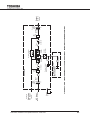
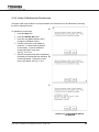
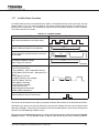
When the UPS stop signal is sent to the UPS through pin 2 and 3 of the external contact interface, it is
possible to automatically reset the following operating systems (OS), which can automatically implement
the shutdown function and restart the operation: Windows NT, IBM OS/2 LAN server, LANtastic
Parameter 641 – UPS Shutdown by LAN Input Signal Enabled/Disabled
Parameter 642 – UPS Shutdown by LAN Signal Permitted Time Window (Adjustable)
With the UPS Shutdown by LAN Signal function enabled, when line power fails and the UPS goes to
backup the LAN will shutdown even if the UPS returns to normal mode during the shutdown process.
LAN shutdown can take several minutes. The UPS Shutdown by LAN Signal function has a companion
UPS Shutdown by LAN Signal Permitted Time Window parameter that can be set to allow sufficient
time to complete the LAN shutdown process (default: 10 minutes) even if line power is restored during LAN
shutdown.
LAN shutdown is treated as a restart after battery shutdown. The restart of the LAN will be determined by
the Restart After Battery Shutdown timer.
Connect only the UPS stop signal to the external contact interface for automatic processing so that the UPS
output will not be turned off by mistake.
If the computer is started/restarted within 10 minutes after the recovery from a power failure, the
power supply may be reset while the computer is restarting.
10.3
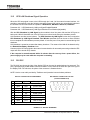
RS-232C
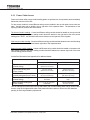
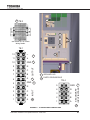
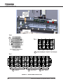
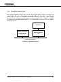
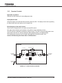
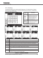
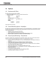
The RS-232C port just to the right of the display PCB can be used by authorized service personnel. The
port is provided using a DB9 female connector located to on the inside of the UPS door just to the right of
the Display PCB. For reference, the pinout of the connector is illustrated below.
NOTE: Use the cross cable provided by Toshiba to avoid potential communications problems.
RS-232C CONNECTOR PIN ASSIGNMENT
Pin
I/O
1
Symbol
DB9 FEMALE CONNECTOR OUTLINE
(FACING CONNECTOR)
Description
This pin is not used
2
Input
RXD
Receive data
3
Output
TXD
Transmit data
4
Output
DTR
Data Terminal Ready
5
-
SG
Signal ground
6
Input
DSR
Data Set Ready
7
Output
RTS
Request to Send
8
Input
CTS
Clear to Send
9
This pin is not used
FIGURE 10.2 – RS-232C INTERFACE
52
4400 Series Installation and Operation Manual – 64527-003