1
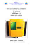
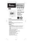
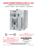
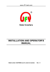
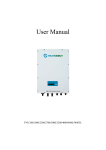
Quick Reference (extract from User Manual)
For the full User Manual please visit:
http://new.abb.com/power-converters-inverters/solar/string/single-phase/pvi-5000kw-6000kw
PVI-5000/6000-TL-OUTD (5.0 to 6.0 kW)
Content:
Instruments - Description of keyboard and LED Panel
Operation - LED behaviour
Operations - Description of the menus
Operations - Statistics Menu
Operations - Info Menu
6 - Instruments
Description of keyboard and LED Panel
Using the combination of keyboard keys, under the display, it is possible
to set values or scroll through the data items to view them. LED indicators are located alongside the keyboard, indicating the operating state of
the inverter.
LED
POWER (GREEN)
Description
ON if the inverter is working correctly.
Flashes when checking the grid or if there is insufficient sunlight.
ALARM (YELLOW) The inverter has detected an anomaly; the anomaly is shown on the display.
GFI (RED)
Ground fault on the DC side of the PV generator; the error is shown on the display.
The LEDs, in various multiple available combinations, can signal multiple conditions other
than the original single condition; see the various descriptions explained in the manual.
UP
DOWN
ENTER
Description
It is used to access the main menu, to go back to the previous menu or to go back to the
previous digit to be edited.
It is used to scroll up the menu options or to shift the numerical scale in ascending order.
It is used to scroll down the menu options or to shift the numerical scale in descending order.
It can be used to confirm an action, to access the submenu for the selected option (indicated
by the > symbol) or to switch to the next digit to be edited. By pressing and holding the key,
Locked or Cyclical.
the cyclical display of the parameters can be:
The Keys, in various multiple available combinations, allow you to access actions other than the
original single action; see the various descriptions explained in the manual.
000410BG
KEYS
ESC
- 60 -
7 - Operation
LED behaviour
LED status
Operating state
green:
yellow:
red:
Firmware programming
The inverter firmware is being programmed
green:
yellow:
red:
Night mode (inverter automatically switches off)
The inverter is in night time switch-off mode (input voltage less than 70% of the set start-up
voltage).
green:
yellow:
red:
Inverter initialisation
This is a transitional state during verification of the operating conditions. During this stage the
inverter checks that the conditions for connecting to the grid are met.
green:
yellow:
red:
The inverter is connected and is feeding power into the grid
Normal operation During this stage, the inverter automatically tracks and analyses the photovoltaic generator's maximum power point (MPP).
green:
yellow:
red:
Disconnection from the grid
Indicates no grid voltage. This condition does not allow the inverter to connect to the grid (the
inverter display shows the message "Missing Grid").
green:
yellow:
red:
Indication of Warning (W message codes) or Error (E message codes) states
Indicates that the inverter control system has detected a warning (W) or error (E). The display
shows a message indicating the type of problem found (see Alarm messages).
green:
yellow:
red:
• Ventilation anomaly
Indicates an anomaly in the operation of the internal ventilation system that could limit output
power at high ambient temperatures.
• Failed association of internal inverter components (after replacement)
Indicates that the installed wiring box (only in the event of a replacement) was already associated with another inverter and cannot be associated with the new inverter
• Overvoltage surge arresters triggered (where fitted)
Indicates that any class II overvoltage surge arresters installed on the AC or DC side have
been triggered
• String protection fuses triggered (where fitted)
Indicates that one or more input string protection fuses that may be installed have been triggered
• Autotest (for Italian grid standards only)
The inverter is performing a self-test
green:
yellow:
red:
Anomaly in the insulation system of the photovoltaic generator
Indicates that a leakage to ground from the FV generator has been detected, causing the
inverter to disconnect from the grid.
- 66 -
000034EG
The following table shows all the possible activation combinations of LEDs
= LED On
on the LED panel according to the operating status of the inverter.
= LED flashing
= LED Off
= Any one of the conditions
described above
7 - Operation
Description of the menus
The inverters are equipped with a Display 07 , consisting of 2 lines of 16
characters each, which can be used to:
• Display the operating state of the inverter and the statistical data
• Display the service messages for the operator
• Display the alarm and fault messages for the operator
• Changing the settings of the inverter
General information
While the inverter is operating, the display shows various items of information on the main parameters measured, the operating conditions and
the inverter’s operating status.
The display cycles through the information when the icon is shown
on the display; if the icon shown on the display is a padlock it means
that the display of information is locked and the UP and DOWN buttons
can be used to scroll through the screens of information instead. You can
switch between the two display modes by pressing the ENTER button.
000412BG
The sequence of screens displayed is shown below, with a description of
the parameters monitored.
- 68 -
7 - Operation
No
Errors/Warnings
Errors/Warnings
On
EXXX
Mon 22 Jan 15:55
DOWN
Inverter OK
Mon 22 Jan 15:55
UP
DOWN
UP
Type: Outdoor inverter type (OUTD)
P/N: ABB product identification code
Type OUTD
P/N -xxxxDOWN
UP
S/N: Sequential serial number
FW rel. : Firmware version installed
S/N XXXXXX
FW rel. X.X.X.X
DOWN
E-day
$-day
UP
E-day: Energy produced today
$-day : Today's savings/earnings
xxx.xkWh
xx.xEUR
DOWN
E-tot
$-tot
UP
E-tot: Energy produced since the inverter was commissioned
$-tot : Savings/earnings since the inverter was commissioned
xxxxxkWh
xxxxxkwh
DOWN
UP
Pout
Pout: Instantaneous output power
xxxxW
DOWN
UP
Phase difference set for feeding in reactive power
Reactive power regulation mode currently set
COSp x.xxx
>Regulation Type
DOWN
UP
Tboost
Tinv
DOWN
UP
DOWN
Independent
inputs
Vin1
Iin1
DOWN
Vin2
Iin2
DOWN
Pin1
DOWN
Pin2
DOWN
DOWN
UP
xxxV
xx.xA
Ppk: Maximum output power peak since the inverter was commissioned
Ppk-Day: Maximum daily output power peak
xxxxxW
xxxxxW
UP
Vgrid
Vgrid Avg
DOWN
Tboost: Internal temperature in the booster circuit (DC/DC)
Tinv: Internal temperature in the inverter circuit (DC/AC)
xx.x`C
xx.x`C
Ppk
Ppk-Day
Igrid
Fgrid
Vgrid: Output voltage
Vgrid Avg: Average output voltage
xxxV
xxxV
UP
Igrid: Output current
Fgrid: Output frequency
xx.xV
xx.xxHz
DOWN
UP
Vin
Iin
Parallel
inputs
xxxV
xx.xA
UP
DOWN
UP
UP
Pin
UP
xxxxW
DOWN
UP
Vin: Input voltage
Iin: Input current Vin 1: Input voltage channel 1
Iin 1: Input current channel 1
Vin 2: Input voltage channel 2
Iin 2: Input current channel 2
xxxV
xx.xA
xxxxW
Inverter status. The code for any malfunction will be displayed.
Date and time as set on the inverter
Pin: Instantaneous input power
Pin1: Instantaneous input power channel 1
Pin2: Instantaneous input power channel 2
xxxxW
UP
xx.xMo
xxmA
Riso: Insulation resistance on DC input side (PV generator)
Ileak: Leakage current on DC input side (PV generator)
000412BG
Riso
Ileak
- 69 -
7 - Operation
Statistics Menu
Selecting STATISTICS from the three main sub-menus gives access to:
Statistics
ENTER
1
Lifetime
DOWN
UP
2
Partial
DOWN
UP
3
Today
DOWN
UP
Last 7 days
DOWN
Last month
DOWN
6
UP
Last 365 days
DOWN
5
UP
Last 30 days
DOWN
4
UP
7
UP
User Period
8
1. Lifetime
This section of the menu displays the Lifetime statistics:
• Time: Total operating time
• E-tot: Total energy produced
• Val. : Total production value, calculated using the currency and conversion coefficient set in the relevant section of the SETTINGS menu
• CO2: Amount of CO2 saved compared to fossil fuels
2. Partial
This section of the menu displays the Partial statistics:
• Time: Partial operating time
• E-par: Partial energy produced
• P-Peak: Peak power value
• Val. : Partial production value, calculated using the currency and conversion coefficient set in the relevant section of the SETTINGS menu
• CO2: Partial amount of CO2 saved
3. Today
This section of the menu displays today's statistics:
• E-day: Energy produced today
• P-Peak: Today's peak power value
• Val. : Value of today's production, calculated using the currency and
conversion coefficient
set in the relevant section of the SETTINGS menu
• CO2: Amount of CO2 saved today
- 70 -
000412BG
To reset all the counters of this sub-menu, press the ENTER button for more than 3 seconds.
At the end of this time, you will hear a sound repeated 3 times.
7 - Operation
4. Last 7 days
This section of the menu displays the statistics for the last 7 days:
• E-7d: Energy produced over the last 7 days
• Val. : Value of production over the last 7 days, calculated using the currency and conversion coefficient set in the relevant section of the SETTINGS menu
• CO2: Amount of CO2 saved over the last 7 days
5. Last month
This section of the menu displays the statistics for the last month:
• E-mon: Energy produced during the current month
• Val. : Value of the last month's production, calculated using the currency and conversion coefficient set in the relevant section of the SETTINGS menu
• CO2: Amount of CO2 saved during the current month
6. Last 30 days
This section of the menu displays the statistics for the last 30 days:
• E-30d: Energy produced over the last 30 days
• Val. : Value of production over the last 30 days, calculated using the
currency and conversion coefficient set in the relevant section of the
SETTINGS menu
• CO2: Amount of CO2 saved over the last 30 days
7. Last 365 days
This section of the menu displays the statistics for the last 365 days:
• E-365d: Energy produced over the last 365 days
• Val. : Value of production over the last 365 days, calculated using the
currency and conversion coefficient set in the relevant section of the
SETTINGS menu
• CO2: Amount of CO2 saved over the last 365 days
000412BG
8. User period
This section of the menu displays the statistics for a period chosen by
the user:
Once the start and end dates for the period have been set, the following
data are available:
• E: Energy produced over the selected period
• Val. : Value of production over the selected period, calculated using
the currency and conversion coefficient set in the relevant section of the
SETTINGS menu
• CO2: Amount of CO2 saved over the selected period
- 71 -
7 - Operation
Info Menu
Selecting INFO from the three main sub-menus gives access to:
Info
ENTER
1
Part No.
DOWN
UP
2
Serial No.
DOWN
UP
3
Firmware
DOWN
UP
Country Code
4
1. Part No.
Displays the model code.
2. Serial No.
Displays the serial number and week and year of manufacture of the
equipment .
3. Firmware
Displays the firmware version installed in the equipment.
000412BG
4. Country Code
Displays information on the grid standard set.
- 79 -