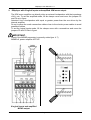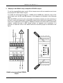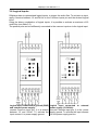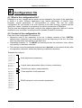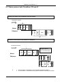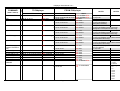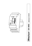
1
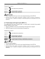
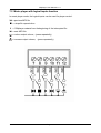
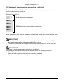
qq
Dinplayer
mod.D01-MKII USER MANUAL
0
Version 2.1
DINplayer User Manual v.2.1
Warranty
DINplayer has a 24 month warranty on the electronic parts, running from the date of
purchase. The warranty will not be valid in case of tampering with the device or in case
personnel not authorised by the manufacturer or by the authorised dealer should carry out
work on it.
N.B. responsibility of the purchaser: in case of operation under warranty, the device must
be packaged so as to prevent damage during transport and shipped to the manufacturer
together with all the accessories.
Warranty rules
1. In order to exercise his warranty rights, the purchaser must enclose with the device a
copy of evidence of purchase duly stamped by the dealer (bill/invoice).
2. The warranty lasts for 24 months for the electronic parts. The warranty is granted at the
point of sale or else directly requested from the manufacturer.
3. The warranty only covers damage to the product which makes it work badly.
4. Work under warranty will only mean repairing or replacing, free of charge, any parts
acknowledged to be defective during manufacture or in their material, including labour
costs.
5. The warranty does not apply to damage caused by negligence or failure to comply with
the instructions, or damage caused by unauthorised people, with a special reference to
the outside parts.
6. Also, the warranty does not apply to damage caused to the device by connection to
unsuitable power sources.
7. The warranty does not cover parts subject to wear after use, or the container if the
material is not defective.
8. The warranty does not include transport costs, which will be paid for by the purchaser
in relation to the manner and time of transport.
9. The warranty will run out after 24 months have elapsed. In this case, service will be
provided charging for the parts replaced, labour costs and transport according to the
current rates.
10. Any dispute will be settled exclusively before the Court of Law of Venice.
Page 1
DINplayer User Manual v.2.1
TABLE OF CONTENTS
1. Introduction
1.1
1.2
1.3
1.4
1.5
1.6
1.7
2.
Installation
2.1
2.2
3.
What is the configuration file?
Content of the configuration file
How it is managed by DINplayer
Preparing the file
Memorising the files in the Flash memory
Audio adjustment parameters
Power amplifier configuration
Logical inputs configuration
Playlist/music player configuration
RS485 serial port communication parameters
Operation with logical inputs
5.1
5.2
6.
Command description
Connection description
Power supply
Vplay output for external relay
DINplayer configurations
Logical inputs
Logical inputs: music player
Configuration file
4.1
4.2
4.3
4.4
4.5
4.6
4.7
4.8
4.9
4.10
5.
Content of the DINplayer kit
Notices
Description and connections
3.1
3.2
3.3
3.4
3.5
3.6
3.7
4.
Chat is DINplayer?
What is Mp3?
Encoder
Decoder
Player
Wave
Audio compression in various formats
Introduction to the logical input operation mode
Binary input command codes
Playlist operation
6.1
6.2
6.3
6.4
Introduction to playlist mode operation – MPLL parameter
Playlist player
Playlist player with logic inputs
Playlist player and RS485
Page 2
DINplayer User Manual v.2.1
7.
Music player mode
7.1
7.2
8.
RS485 serial communication
8.1
8.2
8.3
8.4
8.5
8.6
8.7
8.8
8.9
8.10
8.11
8.12
8.13
8.14
8.15
8.16
8.17
8.18
8.19
9.
Music player function
Music player with logical inputs function
DINplayer and RS485
Serial port communication parameters (config.txt)
Framing error on master
NAK reply by DINplayer
Transmitting a command by master
How to read the figures of the dedicated protocols
When the Master delivers a command to DINplayer
Basic format of the dedicated protocols
Basic set-up of the data transmission
Control codes
Address (ADD)
Command (CMD)
CheckSum (CHK)
Basic protocol
Basic protocol with CheckSum
Basic protocol with CR and LF
Basic protocol with CheckSum, CR and LF
List of commands
Error codes
Specifications
9.1
9.2
Technical features
Obsolete devices disposal
Addendum:
Tabella esempi di comunicazione seriale RS485
Page 3
DINplayer User Manual v.2.1
1
Introduction
1.1 What is DINplayer?
DINplayer is an advanced MP3 player with solid state memory, which has been designed
to play warning messages, voice alerts and all types of audio files, recalled by the use of
logical inputs in binary combination.
Standard DIN clamp housing allows to use it with different automation systems: PLC,
industrial computers, touch screen operated terminals, automatic distributors, commercial
promotion systems and various uses on switchboards.
1.2 What is Mp3?
Mp3 is an acronym for Mpeg-1 layer 3. This is an audio compression standard which
eliminates sounds which the human ear cannot hear via a psycho-acoustic algorithm. The
purpose of this compression is to reduce the space taken up by an audio file while still
ensuring excellent quality. The greater the compression, the less the audio quality. The
right compromise, which guarantees a quality comparable to that of a Compact Disc, is
128 Kbps (thousands of bits per second) which represents the most widely used manner,
and reduces the size of an uncompressed file by 10 times.
1.3 Encoder
Software which compresses audio CDs or wave files into MP3s. There are many software
of this kind, and it is virtually impossible to say which is the best.
1.4 Decoder
Software which decompresses an MP3 audio file in order to send it to a digital-analog
converter and reconstruct the original audio signal.
1.5 Player
Hardware and software system able to read MP3 audio files. DINplayer is able to carry out
this function.
1.6 Wave
High quality audio format (extension .wav), compatible with the tracks of normal music
CD’s. If one uses a wave file in format 44.1 KHz/sec. at 16 bit in stereo, one will get
exactly the same quality as a music CD, but the size of the file is about 10Mb per minute.
1.7 Audio compression in various formats.
The following graphic shows the space taken up by an uncompressed audio file of about 5
minutes (.wav) and compressed in MP3 at 128Kbps (MP3).
51,1 MB
Wave
MP3
4,6 MB
Page 4
DINplayer User Manual v.2.1
2
Installation
2.1 Content of the kit DINplayer
-
n° 1 DINplayer device;
n° 1 DINplayer user manual;
n° 1 flash memory;
2.2 Notices
1. DINplayer has been designed and made to work only with the following mains power
supply: 12÷24VDC.
2. The device must be serviced only by qualified staff.
3. Do not put objects inside the device through the openings, in order to prevent the risk
of fire or shock.
4. Disconnect the device from the power socket before cleaning. Clean the device using a
soft, dry cloth. Do not use liquids or spray which can contain flammable substances.
Obsolete devices disposal :
•
When you find this picture on a device, it means that the device is
compliant with European Directive 2002/96/EC.
•
All electronic and electric devices should be disposed separately from
normal garbage.
•
The proper disposal of old devices, accessories, and of the batteries in
particular, it contributes to prevent possible negative consequences for
human health and for the environment.
•
For more detailed information on the disposal of obsolete devices, contact
the municipality, the garbage disposal service or the shop in which the
product has been acquired.
Page 5
DINplayer User Manual v.2.1
3
Description and connections
3.1 Command description
A - Flash memory introduction slot for Secure Digital or MultiMedia Card.
Command keys:
= precedent MP3 file
= (brief pressure) PLAY / (prolonged pressure) increase output volume
= (brief pressure) STOP / (prolonged pressure) reduce output volume
B - = next MP3 file
IMPORTANT:
- volume control with the keys is active only during the playing of the MP3 file.
lit = MP3 file playing;
C - Green LED:
blinking = DINplayer in STOP.
lit = device is live.
D - Red LED:
Page 6
DINplayer User Manual v.2.1
3.2 Connection description
1 - COM IN
Common inputs (COM INPUT)
2 - +VDC
Power supply 12÷24VDC.
3 - GND
Ground supply / Ground signal of pre-amplified audio output.
5-
OUT L
SPK+
OUT R
6SPK-
Active when device is playing. It supplies the same voltage power of the
DINplayer (VDC) and it can directly drive an external relay (150mA max).
Pre-amplified audio output L channel.
Configurable for Amplified 20W audio output for speaker (4Ω min.)
Pre-amplified audio output R channel.
Configurable for Ground signal of amplified audio output.
7 - IN1
Input for activating 1.mp3 file (direct or bit 0 in binary combination).
8 - IN2
Input for activating 2.mp3 file (direct or bit 1 in binary combination).
9 - IN3
Input for activating 4.mp3 file (direct or bit 2 in binary combination).
10 - IN4
Input for activating 8.mp3 file (direct or bit 3 in binary combination).
IN5
485A
IN6
12 485B
Input for activating 16.mp3 file (direct or bit 4 in binary combination).
Configurable for serial RS485 communication (see chap. 8).
Input for activating 32.mp3 file (direct or bit 5 in binary combination).
Configurable for serial RS485 communication (see chap. 8).
4 - Vplay
11 -
3.3 Power supply
DINplayer may operate with the following voltage power supplies: 12÷24VDC.
In the case of configuration with power amplifier, the use of a suitable power supply is
recommended to supply the required audio power . With a 4Ω loudspeaker, DINplayer can
absorb current peaks of 2A.
The standby consumption is 1W.
3.4 Vplay output for external relay
The output of the DINplayer is of a transistor type and is
optoisolated towards the inside CPU.
When activated, it provides on the output terminal the
same feeding voltage applied on the module. This voltage
may be applied to the input of a PLC or else it may
directly pilot the spool of an outside relay.
The output can provide a maximum current of 150mA and
is equipped with a protection diode for inverse currents
induced by the spool of any outside relay.
The output is activated at the time when the reproduction
of an audio file starts, and is maintained in this state
throughout the duration of the file.
Page 7
DINplayer User Manual v.2.1
3.5 DINplayer Configurations
DINplayer in addition to the 6 logic inputs for the audio files activation has a mono 20W
amplifier to directly drive an external loudspeaker and it can be connected through the
serial port to an RS485 bus, to be controlled by a master system or by a computer.
To configure the device to meet your needs, gently use a screwdriver to lift the clamps
cover and to move the P1, P2, P3, P4 jumpers as displayed below.
1. DINplayer with 6 logical inputs and preamplified STEREO output.
•
In the "factory default configuration" the logical inputs mode is active and the power
amplifier is NOT active.
IMPORTANT:
•
Check if the MOMD parameter is correctly setted (par. 4.7)
DEFAULT: MOMD=2, power amplifier NOT ACTIVE.
6 logical inputs and preamplified
STEREO output (DEFAULT)
Page 8
DINplayer User Manual v.2.1
2. DINplayer with 6 logical inputs and amplified 20W mono output.
The 20W mono amplifier can directly drive an external loudspeaker with the impedance
of 4Ω min. To set the amplified mode, lift the clamps cover and move the jumpers P3
and P4 as in figure.
Attention! Use a loudspeaker with equal or greater power than the one driven by the
internal amplifier.
Do not to place the audio connection cables close to the electric power cables to avoid
possible troubles.
To set the logical inputs mode, lift the clamps cover with a screwdriver and move the
jumpers P3 and P4 like in figure.
•
IMPORTANT:
Check if the MOMD parameter is correctly setted (par. 4.7)
MOMD=0, power amplifier ACTIVE.
6 logical inputs and amplified
MONO output
Page 9
DINplayer User Manual v.2.1
3. DINplayer with RS485 and premaplified STEREO output.
To set the preamplified output mode, lift the clamps cover with a screwdriver and move
the jumpers P3 and P4 like in figure.
To enable the serial port through the 11/485A and 12/485B pins, raise the cover of the
device and move the P1 and P2 jumpers of the diagram as indicated in the following
figure.
With the RS485 connection one must supply termination resistors on both extremes of
the line, to avoid the generation of stationary waves and to define the impedance of the
lines even in absence of transmission. DINplayer already has within itself a termination
resistor, enabled through a JP1 bridge jumper; to activate such resistance it is
sufficient to raise the cover of the device and move the JP1 jumper as indicated in the
figure.
RS485 and preamplified STEREO
output
Page 10
DINplayer User Manual v.2.1
4. DINplayer with RS485 and amplified 20W MONO output.
The 20W mono amplifier can directly drive an external loudspeaker with the impedance
of 4Ω min. To set the amplified mode, lift the clamps cover and move the jumpers P3
and P4 like in figure.
Attention! Use a loudspeaker with equal or greater power than the one driven by the
internal amplifier. Do not place the audio connection cables close to the electric power
cables to avoid possible troubles.
To enable the serial port through the 11/485A and 12/485B pins, raise the cover of the
device and move the P1 and P2 jumpers of the diagram as indicated in the following
figure.
With the RS485 connection one must supply termination resistors on both extremes of
the line, to avoid the generation of stationary waves and to define the impedance of the
lines even in absence of transmission. DINplayer already has within itself a termination
resistor, enabled through a JP1 bridge jumper; to activate such resistance it is
sufficient to raise the cover of the device and move the JP1 jumper as indicated in the
figure.
RS485 and amplified MONO output.
Page 11
DINplayer User Manual v.2.1
3.6 Logical inputs
DINplayer has six optoisolated logical inputs, to trigger the audio files. To activate an input,
apply a tension between 12 and 24Vdc to the Common inputs pin and the desired logical
input.
Using the binary combination of logical inputs, it is possible to activate a maximum of 63
audio files (see table 5.2).
The positive pole can be indifferently connected to the common inputs or to the logical input.
Logical input connected to ground (GND)
and external power supply:
connect Common input (pin 1) to a tension
between 12 and 24Vdc. To activate the
input connect it to power supply ground.
Logical input connected to external
power supply (12-24Vdc):
connect Common input (pin 1) to the power
supply ground. To activate the input connect
it to the power supply positive.
Page 12
DINplayer User Manual v.2.1
Logical input connected to ground (GND)
and internal power supply:
connect the Common input (pin 1) to the
DINplayer power supply (12-24Vdc). To
activate the input connect it to ground
(GND).
Logical input connected to positive pole
and internal power supply:
Connect the Common input (pin1) to the
DINplayer power supply ground.
To activate the input connect it to the
DINplayer power supply positive pole.
Page 13
DINplayer User Manual v.2.1
3.7 Logical input: music player.
In music player mode (see chapter 7), logical inputs have the typical player functionality, like in
the figure.
Page 14
DINplayer User Manual v.2.1
4
Configuration file
4.1 What is the configuration file?
DINplayer is a very versatile device which can be adapted to the needs of the application
in which it is used. Different applications may require adjustment of volume, tone,
loudness, special parameters of communication or timing. The text file, called
‘configuration file’ and stored in the main directory of the flash memory, together with the
audio files, makes it possible to programme the various parameters of DINplayer.
This file must be assigned the name config.txt (this extension has been used so it can be
modified by any text editor, including those for portable PocketPC terminals).
4.2 Content of the configuration file
Each line of the configuration file consists of:
• Mnemonic code of the parameter to be set. It always consists of four CAPITAL
alphanumeric characters, and must always be at the beginning of the line. No more
than one parameter is permitted on the same line.
• Separating character. ‘=’. This MUST be inserted just after the mnemonic code, without
any spacing or tabulation character.
• The relevant numerical parameter expressed as a decimal, to be inserted directly after
the separation character, without any spacing or tabulation character.
Example file config.txt:
LOUT=14
LLOU=10
LTRE=14
LBAS=10
TPCM=10
MICP=1
MIRS=1
Audio adjustment parameters
Logical inputs parameters (direct or binary combinaton)
MPLL=1
Playlist/music player mode parameter
MOMD=0
Power amplifier on/off parameter
CMAD=0
CMCK=1
CMCL=0
CMBR=3
CMPR=0
CMSB=1
CMDB=8
CMDR=0
CMNR=0
RS485 serial port communication parameters
Page 15
DINplayer User Manual v.2.1
4.3 How it is managed by DINplayer
At the time the device is turned on, or when the flash memory is inserted, DINplayer will
start to read the main directory of the memory; once it has found the file config.txt, it
interprets the parameters inserted in each line, memorising them permanently in its
internal memory, of a non volatile kind. The parameters therefore stay in memory even
after the device has been turned off. This is why it is not indispensable for the
configuration file to be always present in the flash memory: once all the parameters have
been acquired, this file can also be deleted.
NOTE: If it is necessary to configure various DINplayers with the same parameters, one
can prepare a single flash memory with the appropriate config.txt file, alternately insert this
memory on all the modules to be configured, then insert the memory with the audio files
only.
4.4 Preparing the file
To create the file, one can use an ordinary text editor (like Windows Notebook). The file
must be saved as a pure text file (.txt). Should other programmes be used (e.g. Microsoft
Word) one must be careful to save the document as “text only”: otherwise, control
characters would be inserted which would make it impossible for DINplayer to interpret this
file.
4.5 Memorising the files in the flash memory
The configuration file and all the MP3 audio files can be memorised in the flash memory
via a special USB reader/writer for PC.
Page 16
DINplayer User Manual v.2.1
4.6 Audio adjustment parameters
DINplayer allows for the following audio adjustments:
• adjustments general amplified/pre-amplified output.
• adjustment of loudness level.
• adjustment of high tone level.
• adjustment of low tone level.
The following tables show the relation between the value set in the configuration file and
the actual value of the audio parameter.
LOUT (DEFAULT=14)
general output amplified/pre-amplified level*
LOUT= 0 1
2 3 4 5 6 7 8 9 10 11 12 13 14 15 16 17 18 19 20
dB
OFF -55 -35 -28 -23 -20 -17 -14 -12 -10 -8
-6
-4
-2
0
+2 +4 +6 +8 +10 +12
level
* the dB value is always related to the premaplified signal, also with the internal power amplifier
activated!
LLOU (DEFAULT=10)
loudness level
LLOU= 0
4
dB
level
0
1
2
3
6
7
LTRE= 0
9
10 11 12 13 14 15 16 17 18 19 20
1
-12 -10
high tone level
2
3
4
5
6
7
8
9
-8
-7
-6
-5
-4
-3
-2
-1
LBAS (DEFAULT=10)
low tone level
LBAS= 0
dB
level
8
+0,5 + 1 +1,5 + 2 +2,5 + 3 + 4 + 5 + 6 + 7 + 8 + 9 + 10 +11 + 12 + 13 + 14 + 15 + 16 + 17
LTRE (DEFAULT=14)
dB
level
5
1
-12 -10
2
3
4
5
6
7
8
9
-8
-7
-6
-5
-4
-3
-2
-1
10 11 12 13 14 15 16 17 18 19 20
0
+1 +2 +3 +4 +5
+6
+7
+8 +10 +12
10 11 12 13 14 15 16 17 18 19 20
0
+1 +2 +3 +4 +5
+6
+7
+8 +10 +12
4.7 Power amplifier configuration
In the factory default configuration the power amplifier is NOT active (preamplfied
configuration). To switch on the power amplifier, set the MOMD parameter in the
config.txt file.
Mnemonic
Description parameter
Internal amplifier configuration:
MOMD
(DEFAULT=2)
0 = Muting ON. The power amplifier is active only during the MP3 files
playing. When DINplayer is in STOP mode the power amplifier is in
Standby.
1 = Muting OFF. Power Amplifier always active, . Also when DINplayter is in
STOP mode.
2 = Power amplifier NOT ACTIVE (default – use this setting in preamplified
configuration).
Page 17
DINplayer User Manual v.2.1
IMPORTANT:
•
In case of power amplifier excessive high temperature , the thermal protection disables
the audio output. To reactivate the amplifier normal operation switch the DINplayer off
and then on again.
4.8 Input management parameters
The playing of the files takes place by activating the available logical inputs, the activation
modes are set through the TPCM MICP and MIRS parameters inserted in the
configuration files.
Mnemonic
Description of timing parameter
Setting the persistence time of the input command (time to wait before
DINplayer is able to interpret the input command) expressed in decimals of
milliseconds (value between 0 and 255 in decimal).
0 = no delay
TPCM
1 =10mSeconds
(DEFAULT=10)
2 =20mSeconds
100 = 1 second
200 = 2 seconds
250 = 2,5 seconds (max. value)
Setting Mode Input Continuous Play
0 = having terminated the playing of the codified file, requested from the
MICP
input code, DINplayer goes in standby.
(DEFAULT=1)
MIRS
(DEFAULT=1)
1 = the requested codified file is continuously played until the relevant input
code is inserted.
Setting Mode Input ReStart
0 = repeated activation or deactivating of the same input code does not
influence the playing of the relevant file. Only the activation of a different
code can block the playing underway and activate the playing of the new
requested file.
1 = in the moment in which an input code is enabled the playing of the of the
relevant file from its beginning takes place, even if it is already in play.
4.9 Playlist/music player configuration
Mnemonic
Description parameter
0= playlist NOT ACTIVE.
MPLL
(DEFAULT=1)
1= playlist ACTVE.
16= music player mode
Page 18
DINplayer User Manual v.2.1
4.10 RS485 serial port communication parameters
IMPORTANT:
•
The RS485 is active in every configuration.
The following table lists the values of the parameters needed to connect DINplayer to a
Master system coordinating it (protocol, speed, timings, etc.).
Mnemonic
CMAD
(DEFAULT=0)
CMCK
Description
Address DINplayer in the 485 bus (ADD) (Value between 0 and 63 in decimal).
IMPORTANT: This address MUST be univocal, two devices with the same
address can not co-exist on the same bus.
Enabling introduction of the Checksum:
0= Checksum deactivated
1= Checksum activated
Enabling introduction of end-of-pack
characters CR and LF (hexadecimal values
OD and 0A)
0= No CR and LF
1= Insertion of CR and LF activated
(DEFAULT=1)
CMCL
(DEFAULT=0)
Baud rate (communication speed in bits
(DEFAULT=3) per second)
CMBR
CMPR
Parity Bits:
0= no parity
1= odd parity
2= even parity
Number of Stop Bits
1=1 stopBit
2=2 stopBits
Number of data bits
7=7 bits per datum
8=8 bits per datum
(DEFAULT=0)
CMSB
(DEFAULT=1)
CMDB
(DEFAULT=8)
Minimum delay between end of reception
(DEFAULT=0) of the pack and delivery of the reply.
(Value expressed in tenths of msec
between 0 and 15 in decimal)
CMDR
CMNR
0=1200 bps
1=2400 bps
2=4800 bps
3=9600 bps
Deactivate all replies:
0= Minimum delay of about 4msec
1= Minimum delay of 10msec
2= Minimum delay of 20msec
0= standard function, every command is
followed by a confirmation or error reply.
1= all replies deactivated.
(DEFAULT=0)
Page 19
DINplayer User Manual v.2.1
5
Operation with logical inputs (MPLL=0)
5.1 Introduction to the logical input operation mode
DINplayer can also play individual (message) audio files with direct selection from six inputs.
Activation is carried out directly or in binary combination, up to a maximum of 255 files,
using the inputs IN1, IN2, IN3, IN4, IN5, IN6.
Activating the inputs in binary combination, one can launch the playing of a maximum of
63 messages, naming the audio files as shown on the table.
Player modalities are set with the following parameters:
Example file config.txt:
LLOU=10
LTRE=14
LBAS=10
MOMD=0
Audio adjustment parameters
Power amplifier mode
MPLL=0
Playlist mode
TPCM=10
MICP=1
MIRS=0
Logical inputs in binary combination parameters.
Mnemonic
Description of timing parameter
Setting the persistence time of the input command (time to wait before
DINplayer is able to interpret the input command) expressed in decimals of
milliseconds (value between 0 and 255 in decimal).
0 = no delay
TPCM
1 =10mSeconds
(DEFAULT=10)
2 =20mSeconds
100 = 1 second
200 = 2 seconds
250 = 2,5 seconds (max. value)
Setting Mode Input Continuous Play
0 = having terminated the playing of the codified file, requested from the
MICP
input code, DINplayer goes in standby.
(DEFAULT=1)
MIRS
(DEFAULT=1)
•
1 = the requested codified file is continuously played until the relevant input
code is inserted.
Setting Mode Input ReStart
0 = repeated activation or deactivating of the same input code does not
influence the playing of the relevant file. Only the activation of a different
code can block the playing underway and activate the playing of the new
requested file.
1 = in the moment in which an input code is enabled the playing of the of the
relevant file from its beginning takes place, even if it is already in play.
IMPORTANT:
volume control with the keys is active only during the playing of the MP3 file.
Page 20
DINplayer User Manual v.2.1
5.2 Binary input command codes
Activating the inputs in binary combination, one can launch the playing of a maximum of
63 messages, naming the audio files as shown on the following table.
INPUT
1 2 3 4 5 6
O
1
O
1
O
1
O
1
O
1
O
1
O
1
O
1
O
1
O
1
O
1
O
1
O
1
O
1
O
1
O
1
O
1
O
1
O
1
O
1
O
O
O
1
1
O
O
1
1
O
O
1
1
O
O
1
1
O
O
1
1
O
O
1
1
O
O
1
1
O
O
1
1
O
O
1
1
O
O
1
1
O
O
O
O
O
1
1
1
1
O
O
O
O
1
1
1
1
O
O
O
O
1
1
1
1
O
O
O
O
1
1
1
1
O
O
O
O
1
1
1
1
O
O
O
O
O
O
O
O
O
1
1
1
1
1
1
1
1
O
O
O
O
O
O
O
O
1
1
1
1
1
1
1
1
O
O
O
O
O
O
O
O
1
O
O
O
O
O
O
O
O
O
O
O
O
O
O
O
O
1
1
1
1
1
1
1
1
1
1
1
1
1
1
1
1
O
O
O
O
O
O
O
O
O
O
O
O
O
O
O
O
O
O
O
O
O
O
O
O
O
O
O
O
O
O
O
O
O
O
O
O
O
O
O
O
O
1
1
1
1
1
1
1
1
1
FILE
(.mp3)
=
=
=
=
=
=
=
=
=
=
=
=
=
=
=
=
=
=
=
=
=
=
=
=
=
=
=
=
=
=
=
=
=
=
=
=
=
=
=
=
=
stand by
1
2
3
4
5
6
7
8
9
10
11
12
13
14
15
16
17
18
19
20
21
22
23
24
25
26
27
28
29
30
31
32
33
34
35
36
37
38
39
40
INPUTS BINARY COMBINATION
individual activation input IN 1
individual activation input IN 2
binary combination inputs IN 1 + IN 2
individual activation input IN 3
binary combination inputs IN 1 + IN 3
binary combination inputs IN 2 + IN 3
binary combination inputs IN 1 + IN 2 + IN 3
individual activation input IN 4
binary combination inputs IN 1 + IN 4
binary combination inputs IN 2 + IN 4
binary combination inputs IN 1 + IN 2 + IN 4
binary combination inputs IN 3 + IN 4
binary combination inputs IN 1 + IN 3 + IN 4
binary combination inputs IN 2 + IN 3 + IN 4
binary combination inputs IN 1 + IN 2 + IN 3 + IN 4
individual activation input IN 5
binary combination inputs IN 1 + IN 5
binary combination inputs IN 2 + IN 5
binary combination inputs IN 1 + IN 2 + IN 5
binary combination inputs IN 3 + IN 5
binary combination inputs IN 1 + IN 3 + IN 5
binary combination inputs IN 2 + IN 3 + IN 5
binary combination inputs IN 1 + IN 2 + IN 3 + IN 5
binary combination inputs IN 4+ IN 5
binary combination inputs IN 1 + IN 4 + IN 5
binary combination inputs IN 2 + IN 4 + IN 5
binary combination inputs IN 1 + IN 2 + IN 4 + IN 5
binary combination inputs IN 3 + IN 4 + IN 5
binary combination inputs IN 1 + IN 3 + IN 4 + IN 5
binary combination inputs IN 2 + IN 3 + IN 4 + IN 5
binary combination inputs IN 1 + IN 2 + IN 3 + IN 4 + IN 5
individual activation input IN 6
binary combination inputs IN 1 + IN 6
binary combination inputs IN 2 + IN 6
binary combination inputs IN 1 + IN 2 + IN 6
binary combination inputs IN 3 + IN 6
binary combination inputs IN 1 + IN 3 + IN 6
binary combination inputs IN 2 + IN 3 + IN 6
binary combination inputs IN 1 + IN 2 + IN 3 + IN 6
binary combination inputs IN 4 + IN 6
Page 21
DINplayer User Manual v.2.1
INPUT
1 2 3 4 5 6
1
O
1
O
1
O
1
O
1
O
1
O
1
O
1
O
1
O
1
O
1
O
1
O
1
1
O
O
1
1
O
O
1
1
O
O
1
1
O
O
1
1
O
O
1
1
O
O
O
1
1
1
1
O
O
O
O
1
1
1
1
O
O
O
O
1
1
1
1
1
1
1
1
1
1
1
O
O
O
O
O
O
O
O
1
1
1
1
1
1
1
1
O
O
O
O
O
O
O
1
1
1
1
1
1
1
1
1
1
1
1
1
1
1
1
1
1
1
1
1
1
1
1
1
1
1
1
1
1
1
1
1
1
1
1
1
1
1
FILE
(.mp3)
=
=
=
=
=
=
=
=
=
=
=
=
=
=
=
=
=
=
=
=
=
=
=
41
42
43
44
45
46
47
48
49
50
51
52
53
54
55
56
57
58
59
60
61
62
63
INPUT’S BINARY COMBINATION
binary combination inputs IN 1 + IN 4 + IN 6
binary combination inputs IN 2 + IN 4 + IN 6
binary combination inputs IN 1 + IN 2 + IN 4 + IN 6
binary combination inputs IN 3 + IN 4 + IN 6
binary combination inputs IN 1 + IN 3 + IN 4 + IN 6
binary combination inputs IN 2 + IN 3 + IN 4 + IN 6
binary combination inputs IN 1 + IN 2 + IN 3 + IN 4 + IN 6
binary combination inputs IN 5 + IN 6
binary combination inputs IN 1 + IN 5 + IN 6
binary combination inputs IN 2 + IN 5 + IN 6
binary combination inputs IN 1 + IN 2 + IN 5 + IN 6
binary combination inputs IN 3 + IN 5 + IN 6
binary combination inputs IN 1 + IN 3 + IN 5 + IN 6
binary combination inputs IN 2 + IN 3 + IN 5 + IN 6
binary combination inputs IN 1 + IN 2 + IN 3 + IN 5 + IN 6
binary combination inputs IN 4 + IN 5 + IN 6
binary combination inputs IN 1 + IN 4 + IN 5 + IN 6
binary combination inputs IN 2 + IN 4 + IN 5 + IN 6
binary combination inputs IN 1 + IN 2 + IN 4 + IN 5 + IN 6
binary combination inputs IN 3 + IN 4 + IN 5 + IN 6
binary combination inputs IN 1 + IN 3 + IN 4 + IN 5 + IN 6
binary combination inputs IN 2 + IN 3 + IN 4 + IN 5 + IN 6
binary combination inputs IN 1 + IN 2 + IN 3 + IN 4 + IN 5 + IN 6
Page 22
DINplayer User Manual v.2.1
6
Playlist operation
6.1 Introduction to playlist mode operation (MPLL=1).
DINplayer is able to follow a sequence or list of music pieces; this play list is a simple text
file called playlist.txt which can be inserted in the main directory of the same memory
containing the audio files (this extension is used so it can be modified via a handy PocketPC
portable terminal).
Use the MPLL (Mode PLayList) parameter to set this mode.
Mnemonic
Parameter description
Playlist mode configuration
MPLL
(DEFAULT=1)
0=Playlist NOT ACTIVE
1=Playlist ACTIVE
6.2 Playlist player
Follow a few, easy rules to set the sequence:
Example: playlist with 10 mp3 files:
Intro
Rock1
Jazz2065
Sinatra
Alarm626
Warning4
Sugar
Relax01
NewAge10
Easy23
IMPORTANT:
•
•
•
Rename the MP3 audio files with numbers or names with max.
8 characters.
Do not write in the extension (.mp3
Max. 500 pieces per playlist
Fit the memory into its seat and wait for DINplayer to read the playlist in order to check the
list of pieces contained.
At the end of the reading operation, if the names of the pieces have been fitted in correctly,
DINplayer will automatically start to play the musical items in the programmed sequence.
The 4 keys in the front panel, work as follows:
= precedent MP3 file
= (brief pressure) PLAY / (prolonged pressure) increase output volume
= (brief pressure) STOP / (prolonged pressure) reduce output volume
= next MP3 file
Page 23
DINplayer User Manual v.2.1
Example file config.txt:
LLOU=10
LTRE=14
LBAS=10
MOMD=0
MPLL=1
Audio adjustment parameters
Power amplifier parameter
Playlist mode parameter
IMPORTANT:
•
volume control with the keys is active only during the playing of the MP3 file.
•
Pressing STOP during playlist reproduction, DINplayer stops the sequence reproduction.
Then, when PLAY is pressed, the playlist is reactivated playing the interrupted file from the
beginning.
6.3 Playlist player with logical inputs (MPLL=1)
The logical inputs work also in playlist mode. If a logical input is activated during playlist
playing, DINplayer acts as follows:
1. Playlist is SOPPED and the file corresponding to the logical input is played
2. RESTART playlist from the file following the interrupted one.
Example file config.txt:
LLOU=10
LTRE=14
LBAS=10
MOMD=0
Audio adjustment parameters
Power amplifier parameter
MPLL=1
Playlist mode parameter
TPCM=10
MICP=1
MIRS=1
Logical inputs in binary combination parameters.
IMPORTANT:
•
For this mode set MIRS=1.
•
volume control with the keys is active only during the playing of the MP3 file.
•
Pressing STOP during playlist reproduction, DINplayer stops the sequence reproduction.
Then, when PLAY is pressed, the playlist is reactivated playing the interrupted file from the
beginning.
Page 24
DINplayer User Manual v.2.1
6.4 Playlist player and RS485
The RS485 functionality is always active, also in playlist mode.
If a RS485 command is sent during playlist reproduction, DINplayer acts as follows:
1. Playlist is SOPPED and the file corresponding to the RS485 command is played
2. RESTART playlist from the file following the interrupted one.
Example file config.txt:
LLOU=10
LTRE=14
LBAS=10
MOMD=0
MPLL=1
CMAD=0
CMCK=1
CMCL=0
CMBR=3
CMPR=0
CMSB=1
CMDB=8
CMDR=0
CMNR=0
Audio adjustment parameters
Power amplifier parameter
Playlist mode parameter
RS485 serial port communication parameters
IMPORTANT:
•
volume control with the keys is active only during the playing of the MP3 file.
•
Pressing STOP during playlist reproduction, DINplayer stops the sequence reproduction.
Then, when PLAY is pressed, the playlist is reactivated playing the interrupted file from the
beginning
Page 25
DINplayer User Manual v.2.1
7
Music Player mode (MPLL=16)
7.1 Music Player function (MPLL=16)
DINplayer works just like a standard player in this mode and does not require any specific
programming (or playlist file). Any MP3 file can be played, even with long names.
Use the MPLL (Mode PlasList) parameter to set this mode (in config.txt).
Example file config.txt:
LLOU=10
LTRE=14
LBAS=10
MOMD=0
MPLL=16
Audio adjustment parameters
Power amplifier parameter
Music player mode parameter
IMPORTANT:
•
volume control with the keys is active only during the playing of the MP3 file.
•
When the Stop button is pressed, DINplayer memorises the track currently being
played; press Play and DINplayer will play the track from the beginning. This function
enables very long file sequences in large flash memories to be played, without having
to re-listen to the entire sequence from the first track.
If you wish to listen to the entire sequence again starting from the first track, just
remove the flash memory of turn the DINplayer off and on again.
The tracks will be played in the sequence in which they are memorised in the flash
memory; if a block of data is transferred then the written sequence in the flash memory will
depend on the operating system used; if a precise sequence is preferred, then we
recommend transferring one MP3 file at a time.
In this mode, DINplayer will automatically start to play the audio file, starting from the first
track, when the device is switched on or when the flash memory is inserted; the user can
run through the files just like listening to an audio CD by using the buttons on the front of
the device or by activating the commands with logical inputs, as in the following table:
The 4 keys in the front panel, work as follows:
= precedent MP3 file
= (brief pressure) PLAY / (prolonged pressure) increase output volume
= (brief pressure) STOP / (prolonged pressure) reduce output volume
= next MP3 file
Page 26
DINplayer User Manual v.2.1
7.2 Music player with logical inputs function
In music player mode, the logical inputs can be used for player control.
= previous MP3 file
= stops file reproduction.
= DINplayer restarts from thebeginning of the interrupted file
= next MP3 file
= reduce output volume, (press repeatedly)
= increase output volume, (press repeatedly)
Page 27
DINplayer User Manual v.2.1
8
Serial RS485 communication
IMPORTANT:
•
The RS485 is active in every configuration.
DINplayer can be connected to an RS485 communication bus through a serial port, which
is controlled from a master system or by a computer.
Due to interference from outside the serial line, one may find anomalous behaviour from
part of the master system which could cause possible damage to DINplayer. To avoid this
mishap one must take the following precautions:
1. Do not let the serial cables transit in the same conduits as power cables or cables with
elevated voltage. Maintain a safety distance of at least 10 cm. between these cables.
2. Connect serial cable screen to the ground the on one of the two sides (do not connect
the screen from both sides); in addition, the ground connection of the screen must not
be made in the same point in which piloted circuits of elevated tension are connected.
3. Cut the voltage of the entire system before beginning the wiring of the serial lines: even
dispersed or parasite currents could damage the modules.
DINplayer withstands serial communication in 4 different modes with the RS485 electrical
standard. This type of serial multipoint communication consents the connection in bus of
up to 32 devices, with a maximum distance of 50 metres.
The DINplayer devices connected to the RS485 bus can not autonomously begin
communication, but they can only respond to a specific request (command) from the
master station (usually a PLC or a computer).
The RS485 connection parameters (speed, parity, check-sum, etc.) are set via the
configuration file config.txt.
IMPORTANT:
•
•
The internal electronics of DINplayer are not galvanically insulated from the RS485
line; in case of short circuit or discharge to ground, it is possible to damage not only
the DINplayer, but even the master system to which it is connected!
For the RS485 connection, one must remember to ignore the transmission echo from
the master that is returning through the serial line.
8.1 DINplayer and RS485
To enable the serial port through the 11/485A and 12/485B pins, raise the cover of the
device and move the P1 and P2 jumpers of the diagram as indicated in the following
figure.
With the RS485 connection one must supply termination resistors on both extremes of the
line, to avoid the generation of stationary waves and to define the impedance of the lines
even in absence of transmission. DINplayer already has within itself a termination resistor,
enabled through a JP1 bridge jumper; to enable such resistance it is sufficient to raise the
cover of the device and move the JP1 jumper as indicated in the figure.
Page 28
DINplayer User Manual v.2.1
P1 and P2 position (Default):
P1, P2 and JP1 position in RS485 mode:
•
•
•
P1 set PIN 11 as logical input (IN5)
P2 set PIN 12 as logical input (IN6)
P1 set PIN 11 as RS485A
• P2 set PIN 12 as RS485B
• JP1 sets RS485 termination’s resistor
(120Ω).
Page 29
DINplayer User Manual v.2.1
8.2 Serial port communication parameters (config.txt)
The parameters of the RS485 serial port (length of the packs, parity, speed, etc.) are set
via the configuration file config.txt.
Example file config.txt:
LLOU=10
LTRE=14
LBAS=10
CMAD=0
CMCK=1
CMCL=0
CMBR=3
CMPR=0
CMSB=1
CMDB=8
CMDR=0
CMNR=0
Audio adjustment parameters
RS485 serial port communication parameters
These parameters must coincide with those of the outside device with which DINplayer is to
communicate.
IMPORTANT:
•
•
To make the modification of these parameters effective, it is necessary to restart DINplayer
after having introduced the flash memory with the file config.txt.
If DINplayer is not used with Playlist or as music player, set MPLL=0 in the config.txt.
IMPORTANT: notes for the Master system
Conditions in which a transmission sequence is initialised.
The DINplayer transmission sequence is initialised under the following conditions:
• When DINplayer is turned on.
• When the data communication has been normally completed.
• When the timeout time for receiving a pack has expired.
Page 30
DINplayer User Manual v.2.1
The following table lists the values of the parameters needed to connect DINplayer to a
Master system coordinating it (protocol, speed, timings, etc.).
Mnemonic
CMAD
(DEFAULT=0)
CMCK
Description
Address DINplayer in the 485 bus (ADD) (Value between 0 and 63 in decimal).
IMPORTANT: This address MUST be univocal, two devices with the same
address can not co-exist on the same bus.
Enabling introduction of the Checksum:
(DEFAULT=1)
Enabling introduction of end-of-pack
(DEFAULT=0) characters CR and LF (hexadecimal values
OD and 0A)
CMCL
Baud rate (communication speed in bits
(DEFAULT=3) per second)
CMBR
0= Checksum deactivated
1= Checksum activated
0= No CR and LF
1= Insertion of CR and LF activated
0=1200 bps
1=2400 bps
2=4800 bps
3=9600 bps
Parity Bits:
0= no parity
1= odd parity
2= even parity
Number of Stop Bits
1=1 stopBit
2=2 stopBits
Number of data bits
7=7 bits per datum
8=8 bits per datum
(DEFAULT=0)
Minimum delay between end of reception
of the pack and delivery of the reply.
(Value expressed in tenths of msec
between 0 and 15 in decimal)
0= Minimum delay of about 4msec
1= Minimum delay of 10msec
2= Minimum delay of 20msec
CMNR
Deactivate all replies:
0= standard function, every command is
followed by a confirmation or error reply.
1= all replies deactivated.
CMPR
(DEFAULT=0)
CMSB
(DEFAULT=1)
CMDB
(DEFAULT=8)
CMDR
(DEFAULT=0)
Message waiting time (CMDR)
This is the delay time of the reply message, required by some computers to switch over
between the state of transmission and the state of reception.
The awaiting time determines the minimum delay before the DINplayer sends data in reply
to the message received from the Master. Set this time at a value different from 0 only if
the specifications of the Master demand it, since the delay determines an extension of the
time needed to complete the command.
Page 31
DINplayer User Manual v.2.1
8.3 " Framing" error on the master
When commercial RS-485 interfaces are used on the master, a Framing error may take
place if nothing is being transmitted on the serial line.
In order to avoid this mishap, it is indispensable that the system master ignores all the data
until it has received one of the STX, ACK or NAK characters coming from a DINplayer.
8.4 NAK reply by DINplayer
The reply with the character NAK is sent from DINplayer to the master when any kind of
error is detected in the message received.
8.5 Transmitting a command by master
When you send a command from the master to DINplayer using one of the dedicated
protocols, make sure you send it with a delay of at least 10mS starting from the moment
the last command received by DINplayer has been completely performed.
IMPORTANT:
when one is using the RS485 bus (only on a duplex cable) remember to bear in mind or to
ignore the echo of the command that is sent from the master (with RS485 an echo is
always present).
8.6 How to read the figures of the dedicated protocols
When the master reads the data from DINplayer.
(DINplayer > Master)
A
Master
DINplayer
E
N
Q
C
A
C
K
Data
S
T
X
Data
Data
B
a) The data areas A and C indicate the transmission of data from the master to DINplayer.
b) The data area B indicates the transmission of data from DINplayer to the master.
c) The programme of the Master is structured so as to manage the data in the manner
shown on the figure from left to right. Therefore, the data management sequence is A, B, C.
Example : In area A, the character ENQ (05H) is transmitted, followed by all the other data
indicated as " Data" in the figure to the right of the character ENQ.
Page 32
DINplayer User Manual v.2.1
8.7 When the Master delivers a command to DINplayer
(Master > DINplayer)
A
Master
Panelplay
E
N
Q
Data
A
C
K
Data
B
a) The data area A indicates the transmission of data from the master to DINplayer.
b) The data area B indicates the transmission of data from DINplayer to the master.
c) The programme of the master is structured so as to manage the data in the manner
shown on the figure from left to right. Therefore, the data management sequence is A, B.
Example : In area A, the character ENQ (05H) is transmitted, followed by all the other data
indicated as " Data" in the figure to the right of the character ENQ.
8.8 Basic format of the dedicated protocols
DINplayer manages up to four dedicated protocols.
The definition of which of these four protocols must be used by the serial connection, is set
in the configuration file config.txt. (par. 9.2).
The difference among these four formats is due to the presence or absence of CheckSum
and/or of the characters CR (Carriage Return, character 0DH) and LF (Line Feed,
character 0AH).
8.9 Basic set-up of the data transmission
Control code
DINplayer address
Command code
Command data
CheckSum
CR/LF control codes
IMPORTANT:
the introduction of CheckSum at the end of the block of data and characters of CR + LF is
defined in the configuration file.
Page 33
DINplayer User Manual v.2.1
8.10 Control codes
The control codes are characters (they belong to the first 32 ASCII characters and cannot
be printed out) which define the kind of information contained in the pack following them.
The control codes used are those which appear on the following table.
DINplayer initialises the transmission sequence when it receives the character ENQ.
Mnemonic
Code
Description
STX
02H
Start TeXt. Beginning of transmission of reply pack.
ETX
03H
End TeXt. End of reply pack.
ENQ
05H
EnQuiry. Beginning of pack addressed to DINplayer ( or # for
RS485).
ACK
06H
ACKnowledge. Beginning of reply pack: all OK!
LF
0AH
Line Feed. End of line code.
CR
0DH
Carriage Return.
NAK
15H
Not AcKnowledge. Beginning of pack with error code.
N.B. The codes are expressed in hexadecimal.
8.11 Address (ADD)
The address is a number that allows the system Master to establish communication with
one of the various modules connected to the same serial line.
The value of this address is defined in DINplayer through a configuration file config.txt.
•
•
•
IMPORTANT:
when setting the address it is necessary to be careful to not define more than one
module with the same number, otherwise the communication becomes confused and
irregular and the data exchanged will no longer make sense.
The address can assume any value between 00H and 1FH.
The address is expressed in ASCII characters and consists of 2 characters.
Note! BROADCAST Commands (CMAD=00)
DINplayer processes commands received with a 00 address without providing a reply.
8.12 Command (CMD)
This is used to define the operation to be carried out (for example PLAY, reading the state
or setting of the volume). The commands are defined in ASCII characters and consists of
2 characters.
In the following sections of this chapter, we provide the list of commands and every detail
about each command.
Page 34
DINplayer User Manual v.2.1
8.13 CheckSum (CHK)
The CheckSum makes sure that the packs are complete and not corrupted during their
transmission by any noise induced on the line.
The CheckSum is calculated summing the hexadecimal value of the ASCII characters
contained in the data area defined for the CheckSum. The two least significant characters
(in hexadecimal) of the sum represent the CheckSum which is introduced into the two
dedicated ASCII characters at the end of the pack (before any CR and LF characters).
Note ! The sum of the value in decimal of the ASCII codes, converted into hexadecimal,
must give the same result. Introduction and management of the CheckSum is established
by the CMCK parameter of the configuration file.
O
If CMCK=1 has been set, CheckSum will be calculated automatically and added to the
term of the reply pack (the one beginning ’STX’) when this is delivered. When a pack is
received, DINplayer calculates the new CheckSum and compares it with the one
contained in the pack itself; if it agrees, DINplayer goes on to perform the command,
otherwise it delivers an error pack (pack beginning with ‘NAK’).
O
If CMCK=0 has been set, CheckSum will not be delivered in transmission and will not
be compared (also because it is missing in the data) in the received messages. The
following figure shows an example of calculation of CheckSum in a command pack
delivered by the master.
ADD
E
N
Q
CMD
DATA
0 1 5 0 0 1 3 2
CHK
8 C
05H 30H 31H 35H 30H 30H 31H 33H 32H 38H 43H
30H + 31H + 35H + 30H + 30H + 31H + 33H + 32H = 18CH
Page 35
DINplayer User Manual v.2.1
8.14 Basic protocol
Reading the data of the DINplayer from the master
Transmission sequence
Master
E
N
Q
A
D
D
C
M
D
S
T
X
DINplayer
A
D
D
C
M
D
DATA
E
T
X
Command transmission from master to DINplayer
Transmission sequence
Master
E
N
Q
A
D
D
C
M
D
The DATA block is
inserted only if provided
for by command used
DATA
DINplayer
Page 36
A
C
K
A
D
D
C
M
D
N
A
K
A
D
D
C
M
D
E
R
R
DINplayer User Manual v.2.1
8.15 Basic protocol with CheckSum
Reading the data of the DINplayer from the master
Transmission sequence
*
Master
C
M
D
A
D
D
E
N
Q
C
H
K
DINplayer
S
T
X
A
D
D
C
M
D
DATA
E
T
X
C
H
K
*
Command transmission from master to DINplayer
Transmission sequence
*
Master
E
N
Q
A
D
D
C
M
D
DATA
DINplayer
*
The DATA block is
inserted only if provided
for by command used
C
H
K
A
C
K
A
D
D
C
M
D
N
A
K
A
D
D
C
M
D
E
R
R
1. The CheckSum is introduced if the configuration parameter CMCK=1.
2. The CheckSum is calculated summing all the characters marked by an asterisk.
Page 37
DINplayer User Manual v.2.1
8.16 Basic protocol with CR and LF
Reading the data of the DINplayer from the master
Transmission sequence
E
N
Q
Master
C
M
D
A
D
D
C L
R F
DINplayer
S
T
X
A
D
D
C
M
D
DATA
E C L
T R F
X
Command transmission from master to DINplayer
Transmission sequence
Master
E
N
Q
A
D
D
C
M
D
DATA
DINplayer
Page 38
The DATA block is
inserted only if provided
for by command used
C L
R F
A
C
K
A
D
D
C
M
D
C L
R F
N
A
K
A
D
D
C
M
D
E
R
R
C L
R F
DINplayer User Manual v.2.1
8.17 Basic protocol with CheckSum, CR and LF
Reading the data of the DINplayer from the master
Transmission sequence
*
Master
E
N
Q
C
M
D
A
D
D
C
H
K
C L
R F
DINplayer
S
T
X
A
D
D
C
M
D
DATA
E
T
X
C
H
K
C L
R F
*
Command transmission from master to DINplayer
Transmission sequence
*
Master
E
N
Q
A
D
D
C
M
D
DATA
DINplayer
*
C
H
K
C L
R F
The DATA block is
inserted only if provided
for by command used
A
C
K
A
D
D
C
M
D
C L
R F
N
A
K
A
D
D
C
M
D
E
R
R
C L
R F
1. The CheckSum is introduced if the configuration parameter CMCK=1.
2. The CheckSum is calculated summing all the characters marked by an asterisk.
Page 39
DINplayer User Manual v.2.1
8.18 List of commands and operating fields
This table provides the list, with the relevant comments, of all the commands managed by DINplayer.
Description
CMD
Command data
Reply data
abcd
a = State of the player:
S = Stop
P = Play
STATUS request
30
None
STOP
31
None
b = (reserved)
c = (reserved)
d = (reserved)
None
PLAY First
32
None
None
PLAY Next
33
None
None
PLAY Prior
34
None
PLAY File
50
52
None
Name of file without extension
(4 characters only)
Name of file without extension
(4 characters only)
Level in hexadecimal (0..14H)
SET Treble
53
Level in hexadecimal (0..14H)
None
SET Bass
54
Level in hexadecimal (0..14H)
None
SET Loudness
55
None
PLAY FileB
56
PLAY File2B
57
Level in hexadecimal (0..14H)
Name of file without extension
(4 characters only)
Name of file without extension
(4 characters only)
Version of firmware
35
None
State of inputs
37
None
Flash memory size
38
None
P = DINplayer
x = version
xx = Release Version
abcdefgh
a=0
b=0
c = IN 6
d = IN 5
e = IN 4
f = IN 3
g = IN 2
h = IN 1
Size of the flash (MAX. 4 characters)
Title of item being played
39
None
Title of the item (MAX. 12 characters)
PLAY File 2
(automatic STOP before PLAY)
SET Volume
51
None
None
None
None
None
IMPORTANT: in order to manage any error messages correctly with the PLAY File (command
code 50H) and PLAY File 2 (command code 51H) commands, DINplayer will check for the requested MP3 file
with a consequent delay of 800/900 mseconds whilst the reply is sent.
When using the PLAY File B (command code 56H) and PLAY File 2 B (command code 57H) commands,
DINplayer will not check the memory and will immediately send an interpreted command message and the
track will begin to play once the reply has been sent. The following errors are not managed with these
commands: "File not found" (error code 32H) and “PLAY file failed" (error code 33H).
Page 40
DINplayer User Manual v.2.1
8.19 Error codes
The following table lists all the error codes which DINplayer delivers together with the NAK
pack if problems are found.
Code
Description
10H
Failure to convert command code (CMD). It could contain characters which are
outside the representation of a hexadecimal value.
The permitted values are: ‘a’ .. ‘f’ ‘A’ …. ‘F’ ‘0’….’9’.
11H
Failure to convert the value contained in ‘DATA’ into a number. It could contain
characters which are outside the representation of a hexadecimal value.
The permitted values are: ‘a’ .. ‘f’ ‘A’ …. ‘F’ ‘0’….’9’.
12H
Failure to convert the CheckSum (CHK). It could contain characters which are
outside the representation of a hexadecimal value.
The permitted values are: ‘a’ .. ‘f’ ‘A’ …. ‘F’ ‘0’….’9’.
13H
CheckSum wrong.
14H
Reserved error.
20H
Wrong value in the parameter of the command SET_Volume. It could be more
than the maximum permitted value.
21H
Wrong value in the parameter of the command SET_Treble. It could be more
than the maximum permitted value.
22H
Wrong value in the parameter of the command SET_Bass. It could be more
than the maximum permitted value.
23H
Wrong value in the parameter of the command SET_Loudness. It could be
more than the maximum permitted value.
30H
The command PLAY cannot be processed because the flash memory is
missing.
31H
The command PLAY (excluding PLAY File 2) cannot be processed because
DINplayer is already playing. To solve the problem, first send the command
STOP, or else use the command PLAY_File_2 which automatically stops any
file being played.
32H
The file requested via the command PLAY_File or PLAY_File_2 has not been
found.
The four characters inserted as an argument for these commands must
correspond exactly to the name of the file you intend to play, except for the
extension.
E.g.: the command ENQ + 00501234 requires the playing of the file 1234.mp3
on DINplayer with address 00.
33H
Failure to play the requested file. The file could be corrupt.
Page 41
DINplayer User Manual v.2.1
9
SPECIFICATIONS
9.1 Technical features
Power supply …………………… : 12÷24VDC.
Consumption in standby ……… : 1 W
Protection ………………………. : inside fuse, 4A delayed.
Capacity of extractable memory : SD/MMC from 32MB to 1GB.
Input absorption…………..……. : 5 mA
Formats accepted ……………… : MPEG1 layer 3 (file MP3 from 64 to 192 Kbps)
Response in frequency ……….. : 20 ~ 20.000 Hz (±3dB)
Signal/noise ratio …………….... : > 90dB.
Harmonic distortion ………….... : < 0,1%
Output power………………….… : max. 20W ( 24V / 4 Ω ) THD+N= 10%
Audio controls ………………..… : - General output volume control
- Separate control of low and high tones
- Loudness level control
Control keys ……………...…….. : 4 buttons REW, PLAY, STOP, FWD and menu functions.
Classification………………….. : IP 30 on the basis of liquid and dust penetration.
Size………………………..……. : 90x53x59mm. / 2 DIN 43880 modules case hooking up to a
DIN EN60715 guide
9.2 Obsolete devices disposal
•
When you find this picture on a device, it means that the device is
compliant with European Directive 2002/96/EC.
•
All electronic and electric devices should be disposed separately from
normal garbage.
•
The proper disposal of old devices, accessories, and of the batteries in
particular, it contributes to prevent possible negative consequences for
human health and for the environment.
•
For more detailed information on the disposal of obsolete devices, contact
the municipality, the garbage disposal service or the shop in which the
product has been acquired.
Manufactured by:
Noventa di Piave (VE) - ITALY
Product compliant with the safeguard regulations 89/336/EEC and 93/68/EEC about
electromagnetic safety and compatibility.
Page 42
DINplayer User Manual v.2.1
CMD
COMMAND
(CMAD=1, CMCK=0)
TO DINplayer
STATUS REQUEST
HEX
30 05 30 31 33 30
ASCII
ENQ 0130
STOP
PLAY FIRST
31 05 30 31 33 31
32 05 30 31 33 32
ENQ 0131
ENQ 0132
PLAY NEXT
33 05 30 31 33 33
PLAY PRIOR
34 05 30 31 33 34
FROM DINplayer
HEX
02 30 31 33 30 53 4D 30 30 03
02 30 31 33 30 50 4D 30 30 03
06 30 31 33 31
06 30 31 33 32
15 30 31 33 32 33 31
ASCII
STX 0130SM00 ETX
STX 0130PM00 ETX
ACK 0131
ACK 0132
NAK 013231
ENQ 0133
06 30 31 33 33
15 30 31 33 33 33 31
ACK 0133
NAK 013331
ENQ 0134
06 30 31 33 34
15 30 31 33 34 33 31
ACK 0134
NAK 013431
PLAY FILE song.mp3
50 05 30 31 35 30 73 6F 6E 67 ENQ 0150song 06 30 31 35 30
15 30 31 35 30 33 31
ACK 0150
NAK 015031
PLAY FILE fire.mp3
50 05 30 31 35 30 66 69 72 65 ENQ 0150fire
ACK 0150
NAK 015031
PLAY FILE 2 song.mp3
(automatic STOP before
PLAY)
SET VOLUME (0 db - 14)
SET VOLUME (-23 db - 4)
SET VOLUME (off - 00)
SET TREBLE (12 db – 20)
SET BASS (12 db – 20)
SET LOUDNESS(12 db-20)
VERSION OF
FIRMWARE
51 05 30 31 35 31 73 6F 6E 67 ENQ 0151song 06 30 31 35 31
52 05 30 31 35 32 30 30 31 34
52 05 30 31 35 32 30 30 30 34
52 05 30 31 35 32 30 30 30 30
53 05 30 31 35 33 30 30 32 30
54 05 30 31 35 34 30 30 32 30
55 05 30 31 35 35 30 30 32 30
35 05 30 31 33 35
ENQ 01520014
ENQ 01520004
ENQ 01520000
ENQ 01530020
ENQ 01540020
ENQ 01550020
ENQ 0135
STATE OF INPUTS
37 05 30 31 33 37
ENQ 0137
06 30 31 35 30
15 30 31 35 30 33 31
ACK 0151
06 30 31 35 31
ACK 0151
06 30 31 35 32
ACK 0152
06 30 31 35 32
ACK 0152
06 30 31 35 32
ACK 0152
06 30 31 35 33
ACK 0153
06 30 31 35 34
ACK 0154
06 30 31 35 35
ACK 0155
02 30 31 33 35 50 32 30 35 03 STX 0135P205 ETX
02 30 31 33 37 30 30 30 30 30 STX 013700000000
30 30 30 03
ETX
Page 43
NOTE 1
NOTE 2
if in stop mode
if in play mode
if in stop mode
if in play mode (DINplayer
doesn’t perform the action)
if in stop mode
if in play mode (DINplayer doesn't jump to the
following file, it is first required to send a stop)
if in stop mode
if in play mode (DINplayer doesn't jump to the
previous file, it is first required to send a stop)
if in stop mode
if in play mode (DINplayer doesn’t perform the action,
it is first required to send a stop)
if in stop mode
if in play mode (DINplayer doesn’t perform the action,
it is first required to send a stop)
if in play mode (DINplayer restarts from the beginning
of the interrupted file)
if in stop mode
P = DINplayer
x = version
xx = Release
abcdefgh
a=0
b=0
c = IN 6
d = IN 5
e = IN 4
f = IN 3
g = IN 2
h = IN 1
DINplayer User Manual v.2.1
FLASH MEMORY SIZE
TITLE OF ITEM BEING
PLAYED
STOP WITH CHECKSUM
(CMCK=1)
STOP WITH CMCL=1
(without checksum)
STOP WITH CMDL=1
(without checksum)
STOP WITH CMCL=1
(with checksum)
STOP WITH CMCL=1
(with checksum)
STOP (CMAD=255 - FF)
STOP (CMAD=255 - FF)
STOP MULTICAST
CMD
COMAND
(CMAD=1, CMCK=0)
TO DINplayer
FROM DINplayer
NOTE 1
HEX
38 05 30 31 33 38
ASCII
ENQ 0138
HEX
ASCII
02 30 31 33 38 31 32 35 4D 03 STX 0138125M ETX
39 05 30 31 33 39
ENQ 0139
15 30 31 33 39 33 36
NAK 013936
if in stop mode
02 30 31 33 39 47 49 47 49 2E
4D 50 33 03
02 30 31 33 39 47 49 47 4F 2E
4D 50 33 03
02 30 31 33 39 43 41 4C 41 42
52 7E 31 2E 4D 50 33 03
If it is playing son.mp3
06 30 31 33 31
STX 0139SONG.MP3
ETX
STX 0139FIRE.MP3
ETX
STX
0139CALABR~1.MP3
ETX
ACK 0131
06 30 31 33 31 0D 0A
ACK 0131 CR LF
06 30 31 33 31 0D 0A
ACK 0131 CR LF
06 30 31 33 31 0D 0A
ACK 0131 CR LF
06 30 31 33 31 0D 0A
ACK 0131 CR LF
31 05 30 31 33 31 43 35
ENQ 0131C5
31 05 30 31 33 31 0D 0A
ENQ 0131 CR
LF
31 05 30 31 33 31 0D 0A
ENQ 0131 CR
LF
31 05 30 31 33 31 43 35 0D 0A ENQ 0131 CR
LF
31 05 30 31 33 31 43 35 0D 0A ENQ 0131 CR
LF
31 05 46 46 33 31
ENQ 0131
31 05 46 46 33 31
ENQ 0131
31 05 00 00 33 31
ENQ 0131
Control characters:
STX
ETX
ENQ
ACK
NAK
CR
LF
=
=
=
=
=
=
=
0x02
0x03
0x05
0x06
0x015
0x0D
0x0A
NOTE 2
Size of the flash
(MAX. 4 characters)
File title
(if present in ID3, 12
characters MAX; file
name (8 characters
truncated) if the title
is not present.
If it is playing fire.mp3
If it is playing
calabriacrotone.mp3
06 46 46 33 31
ACK FF31
06 46 46 33 31
ACK FF31
no answer with multicast address
IMPORTANT:
•
Address CMAD from 1 to 255 (0x01 – 0xff). Multicast address = 00 (0x00).
•
If checksum is enabled (CMCK=1), DINplayer answers with the present checksum only if there is the
data field.
Page 44